EP0096414A1 - Gerät für die Bearbeitung der Turbinenschaufelbefestigung - Google Patents
Gerät für die Bearbeitung der Turbinenschaufelbefestigung Download PDFInfo
- Publication number
- EP0096414A1 EP0096414A1 EP83105585A EP83105585A EP0096414A1 EP 0096414 A1 EP0096414 A1 EP 0096414A1 EP 83105585 A EP83105585 A EP 83105585A EP 83105585 A EP83105585 A EP 83105585A EP 0096414 A1 EP0096414 A1 EP 0096414A1
- Authority
- EP
- European Patent Office
- Prior art keywords
- cutters
- rotary disk
- groove
- finishes
- disk
- Prior art date
- Legal status (The legal status is an assumption and is not a legal conclusion. Google has not performed a legal analysis and makes no representation as to the accuracy of the status listed.)
- Granted
Links
- 238000003754 machining Methods 0.000 abstract description 19
- 241000191291 Abies alba Species 0.000 abstract description 4
- 230000002093 peripheral effect Effects 0.000 description 11
- 238000000034 method Methods 0.000 description 4
- 239000011295 pitch Substances 0.000 description 3
- 238000006243 chemical reaction Methods 0.000 description 2
- 230000000694 effects Effects 0.000 description 2
- 239000000463 material Substances 0.000 description 2
- 230000015572 biosynthetic process Effects 0.000 description 1
- 238000010276 construction Methods 0.000 description 1
- 230000000994 depressogenic effect Effects 0.000 description 1
- 238000003801 milling Methods 0.000 description 1
- 125000006850 spacer group Chemical group 0.000 description 1
Images



Classifications
-
- B—PERFORMING OPERATIONS; TRANSPORTING
- B23—MACHINE TOOLS; METAL-WORKING NOT OTHERWISE PROVIDED FOR
- B23D—PLANING; SLOTTING; SHEARING; BROACHING; SAWING; FILING; SCRAPING; LIKE OPERATIONS FOR WORKING METAL BY REMOVING MATERIAL, NOT OTHERWISE PROVIDED FOR
- B23D37/00—Broaching machines or broaching devices
- B23D37/22—Broaching machines or broaching devices for special purposes
-
- B—PERFORMING OPERATIONS; TRANSPORTING
- B23—MACHINE TOOLS; METAL-WORKING NOT OTHERWISE PROVIDED FOR
- B23D—PLANING; SLOTTING; SHEARING; BROACHING; SAWING; FILING; SCRAPING; LIKE OPERATIONS FOR WORKING METAL BY REMOVING MATERIAL, NOT OTHERWISE PROVIDED FOR
- B23D37/00—Broaching machines or broaching devices
- B23D37/14—Broaching machines with rotatably-arranged working tools
-
- Y—GENERAL TAGGING OF NEW TECHNOLOGICAL DEVELOPMENTS; GENERAL TAGGING OF CROSS-SECTIONAL TECHNOLOGIES SPANNING OVER SEVERAL SECTIONS OF THE IPC; TECHNICAL SUBJECTS COVERED BY FORMER USPC CROSS-REFERENCE ART COLLECTIONS [XRACs] AND DIGESTS
- Y10—TECHNICAL SUBJECTS COVERED BY FORMER USPC
- Y10T—TECHNICAL SUBJECTS COVERED BY FORMER US CLASSIFICATION
- Y10T409/00—Gear cutting, milling, or planing
- Y10T409/30—Milling
- Y10T409/30784—Milling including means to adustably position cutter
- Y10T409/308568—Plural cutters
-
- Y—GENERAL TAGGING OF NEW TECHNOLOGICAL DEVELOPMENTS; GENERAL TAGGING OF CROSS-SECTIONAL TECHNOLOGIES SPANNING OVER SEVERAL SECTIONS OF THE IPC; TECHNICAL SUBJECTS COVERED BY FORMER USPC CROSS-REFERENCE ART COLLECTIONS [XRACs] AND DIGESTS
- Y10—TECHNICAL SUBJECTS COVERED BY FORMER USPC
- Y10T—TECHNICAL SUBJECTS COVERED BY FORMER US CLASSIFICATION
- Y10T409/00—Gear cutting, milling, or planing
- Y10T409/30—Milling
- Y10T409/309352—Cutter spindle or spindle support
- Y10T409/309408—Cutter spindle or spindle support with cutter holder
-
- Y—GENERAL TAGGING OF NEW TECHNOLOGICAL DEVELOPMENTS; GENERAL TAGGING OF CROSS-SECTIONAL TECHNOLOGIES SPANNING OVER SEVERAL SECTIONS OF THE IPC; TECHNICAL SUBJECTS COVERED BY FORMER USPC CROSS-REFERENCE ART COLLECTIONS [XRACs] AND DIGESTS
- Y10—TECHNICAL SUBJECTS COVERED BY FORMER USPC
- Y10T—TECHNICAL SUBJECTS COVERED BY FORMER US CLASSIFICATION
- Y10T409/00—Gear cutting, milling, or planing
- Y10T409/40—Broaching
- Y10T409/404375—Broaching with plural cutters
-
- Y—GENERAL TAGGING OF NEW TECHNOLOGICAL DEVELOPMENTS; GENERAL TAGGING OF CROSS-SECTIONAL TECHNOLOGIES SPANNING OVER SEVERAL SECTIONS OF THE IPC; TECHNICAL SUBJECTS COVERED BY FORMER USPC CROSS-REFERENCE ART COLLECTIONS [XRACs] AND DIGESTS
- Y10—TECHNICAL SUBJECTS COVERED BY FORMER USPC
- Y10T—TECHNICAL SUBJECTS COVERED BY FORMER US CLASSIFICATION
- Y10T409/00—Gear cutting, milling, or planing
- Y10T409/40—Broaching
- Y10T409/406475—Cutter infeed means
- Y10T409/40665—Imparting rectilinear motion to cutter
- Y10T409/406825—Imparting rectilinear motion to cutter and rotary motion to cutter
Definitions
- This invention relates to apparatus for working on mounting grooves formed at bases of blades on a turbine rotor, and more particularly it deals with an apparatus for providing mounting grooves of fine finishes by maching to what are generally referred to as radial entry type blades fitted to the turbine rotor from the radial direction.
- Turbine blades rotate at high spend in high temperature atmosphere.
- the blades are each formed at the base with a mounting groove in the form of a Christmas tree, and disks integral with the turbine rotor shaft are each formed at the top with a protrusion of a cross-sectional shape conforming to the mounting groove of each blade.
- the disks are each cut out in one portion to allow the mounting grooves of the blades to be fitted over the protrusion of the disk through the cutout.
- the blades thus mounted on the disk are successively moved circumferentially of the disk so that they are securely fitted to the disk in the form of a torus. This process is generally referred to as a radial entry process.
- the end mill cutter has the configuration of a rotary member that can be obtained by rotating a groove of the Christmas tree shape about its center line and is provided with cutting edges at its outer peripheral surface.
- this cutter is rotated to form a groove by macining, it has hitherto been impossible to obtain optimum machining speeds at all the portions of the groove because the machining speeds vary from a portion of the cutter of large diameter to a portion thereof of small diameter.
- the cutter When the mounting groove of the blade is formed by machining, the cutter is moved in an arcuate form in the direction of the groove while being rotated as it passes through the groove. Thus, it is necessary to perform machining in opposite directions at left and right portions of the cutter or upwardly and downwardly. This makes the reactions of machining oriented in opposite directions, so that vibration tends to be produced and it is difficult to give precise finishes to the groove with a high degree of precision.
- One object of this invention is to provide an. apparatus for working on mounting grooves of turbine blades capable of providing the turbine blades by machining with mounting grooves finished with a high degree of precision at high efficiency.
- Another object is to provide an apparatus for working on mounting grooves of turbine blades capable of keeping, when a groove is formed by machining, machining speeds for cutting various portion of the groove substantially at a constant level.
- a disk-shaped member that is rotatable has at its outer peripheral portion a plurality of cutters each in the form of a mounting groove of a turbine blade which, ranging from a cutter for giving coarse finishes to a cutter for giving fine finishes, are arranged equidistantly from one another peripherally of the disk-shaped member, so that it is possible to form in a mounting groove portion of a turbine blade a mounting groove of the predetermined shape and configuration as the disk-shaped member is rotated through a predetermined angle to cause the cutters from the cutter for giving coarse finishes to the cutter for giving fine finishes to pass successively through the mounting groove.
- Fig. 1 shows turbine blades 1 mounted on disks 2a formed integrally with a turbine rotor shaft 2.
- the disks 2a are each formed at the outer periphery with a protrusion 2b in the form of a Christmas tree in cross section, and the turbine blades 1 are each formed at its base la with a mounting groove lb of a cross-sectional shape agreeing with the cross-sectional shape of the protrusion 2b.
- the trubine blades 1 which are exposed to high temperature atmosphere during operation develop centrifugal forces of high magnitude due to high speed rotation.
- surfaces of the groove lb located thicknesswise of the blade are arcuate in shape and the radius r of the arcuate surfaces of projections extending into the groove (only one of the arcuate surfaces is shown) should agree with the distance r between the center line Y-Y of the turbine rotor shaft 2 and the particular arcuate surface, because the outer peripheral surface of the protrusion 2b of each disk 2a of the rotor shaft 2 is formed as a surface of rotation centered at the center line Y-Y of the rotor shaft 2.
- the groove lb of the blade 1 should also have surface of rotation.
- the projections extending transversely inwardly from side walls of the groove 1b have pitches p 1 and P 2 which must agree precisely with the pitches of the corresponding portions of the protrusion 2b of the disk 2a in value.
- the mounting groove lb of the blade shown in Fig. 3 is fitted over the protrusion 2b of the disk 2a of the rotor shift 2, surface 11, 12 and 13 of the projections have acting thereon centrifugal forces developing in the blade 1, so that the surfaces 11, 12 and 13 of the projections of the groove 1b should be in intimate contact with the corresponding surfaces of the protrusion 2b of the disk 2a.
- the mounting groove lb of the turbine blade 1 should be finished such that the pitches P 1 and P 2 of the surfaces 11, 12 and 13 of the projections accurately have the predetermined values.
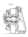
- Fig. 4 shows the working apparatus comprising one embodiment of the invention being supported at a main spindle 25:.by a main body 20 through a bearing sleeve 21 and roller bearing 22 and 23.
- a rotary disk 30 is secured by bolts 26 to a forward end of the main spindle 25.
- the main spindle 25 has thrust bearings 27 . mounted therein for bearing a thrust load applied thereto, and a worm wheel 31 is mounted on the main spindle 25 through a key 29 in a position disposed rearwardly:.of the thrust bearings 27.
- the work wheel 31 includes a center hub 32 secured to the main spindle 25 by lock nuts 33. Meshing with the work wheel 31 is a work 35 which is connected to an electric motor 37 through an output shaft of the latter.
- the main spindle 25 is held at its rear end through a bearing 38 by a rear cover 39, and an angle sensing disk 41 for sensing the angle of rotation of the main spindle 25 and a limit switch 42 located in juxtaposed relation to the 41 are mounted rearwardly of the rear cover 39.
- the disk 41 and limit switch 42 constitute an angle sensing section which is enclosed by a cover 43 to avoid misoperation of the limit switch 42.
- the rotary disk 30 is fitted over guide projections 45 formed integrally with the main body 20 to minimize wobbling of the disk 30 at the surface of rotation when it is driven by the main spindle 25 for rotation.
- An arcuate holder 46 is secured to the front surface of the disk 30 by bolts 47 and has a plurality (seven in the embodiment shown) of cutters 50 mounted on its outer peripheral surface.
- the holder 46 is divided into five blocks, such blocks being mounted in an arcuate form on the surface of the disk 30 (in Fig. 5, only two blocks on the opposite ends are shown, with intermediate three blocks being shown in dash-and-dot lines).
- the rotary disk 30 rotates in the direction of an arrow C in Fig. 5.
- a cutter 50a is the leading cutter and a cutter 50z is the trailing cutter.
- cutters 50 are arranged such that coarse finishes, middling finishes and fine finishes are successively given to the mounting groove of the blade by the cutters 50a to 50z, as the disk 30 rotates.
- a tester 70 for checking the degree of finishes given to the mounting groove lb is located rearwardly of the final finish cutter 50z.
- a workpiece or a turbine blade 1 is secured to a saddle 71 which moves along rails 72.
- the turbine blade 1 secured to the saddle 71 is substantially at the same elevation as the center of the main spindle 25 so that as the saddle 71 moves in clising movement in the direction of arrows D-E, the position of the groove lb can be adjusted with respect to the path of movement of the cutters.
- 75 is an automatic mounting and removing device for mounting the workpiece or the turbine blade 1 on the saddle 71 or removing same therefrom.
- Fig. 6 shows in detail a structure for at- tatching the holder 46 to the rotary disk 30.
- the disk 30 is formed with grooves 78 of a T-shaped cross section extending radially from its center to its outer circumferential surface, and a nut 79 of the T-shape is slidably held in each of the grooves 78.
- the disk 30 is formed on its surface with recesses 81 located at predetermined intervals at right angles to the center grooves 78 of each block of holder 46, and projections 84 are formed at the holder 46 in positions corresponding to those of the recesses 81.
- the holder 46 is secured in place, as shown, by tightening the bolts 47 after the projections 84 are received in the recesses 81.
- the holder 46 is formed at its outer peripheral surface with holes 90 arranged peripherally with a predetermined spacing interval therebetween each for receiving a base 91 of the cutter 50 fitted therein:, Each hole 90 is formed such that its dimension thicknesswise of the cutter agrees with the dimension of the thickness of the cutter 50a, so that when a cutter is forced into the hole 90 as shown in Fig. 8, no gap exists in the direction of thickness.
- Positioning of the cutter is effected by using as a reference a lateral surface 94 of the hole 90 on the side of the disk 30, and the surface of the cutter 50a on a side thereof opposite the lateral surface 94 tapers as indicated at 95.
- a block 96 having a tapering surface corresponding to the tapering surface 95 is forced into the hole 90 from below by means of a bolt 97 so as to press the cutter leftwardly while avoiding dislodging of the cutter 50a upwardly from the hole 90.
- Vertical positioning of the cutter is effected by placing a plurality of thin spacers 98 below the base 91 of the cutter 50a and vertically moving the cutter 50a in the hole 90 from below by means of a bolt 100.
- Fig. 9 shows a turbine blade 1 having a mounting groove to which coarse finishes have been given beforehand.
- a groove lc of trapezoidal configuration is provided at the base la of the blade 1 as by a milling machine.
- the blade 1 that has had coarse finishes given thereto as aforesaid is set in a predetermined position on the saddle 71 and a start button is depressed.
- the motor 37 is actuated to rotate the disk 30 in the direction of the arrow C in Fig. 5. through the worm 35, worm wheel 31 and main spindle 25.
- Rotation of the disk 30 allows the cutters 50a...50z to move successively through the mounting groove of the blade 1 to machine the blade 1 to cut the groove until the groove has its configuration changed from lc shown in solid lines in Fig.
- the cutters 50a...50z are constructed such that their sizes successively grow larger so that the leading cutter 50a is substantially similar to the configuration lc of coarse finishes and the trailing cutter 50z agrees with the configuration 1d of final fine finishes.
- the cutters are also configured such that the areas of the groove cut by different cutters are substantially equal to one another. More specifically, portions of the blade 1 shown in hatches are those removed therefrom by the cutters 50a...50z, and the difference in area between the configurations cut by the preceding cutter and the following cutter is substantially equal to the area obtained by dividing the hatched portions by the number of the blades.
- the cutters simultaneously cut portions of the groove of the blade 1 which are symmetrical with respect to the center line X-X of the groove.
- the portion of the rotary disk 30 at which the cutters 50a are mounted thereon has a peripheral velocity equal to the blade groove cutting velocity, so that the speed of the rotary disk 30 is adjusted in such a manner that the cutting speed is optimized in accordance with the materials of the blade and the cutters.
- the difference in peripheral velocity between an upper end and a lower end of the groove causes a variation to occur in cutting speed.
- the groove has a vertical dimension h which is less than 1/10 the distance R from the tip of the cutter to the center of the disk, the cutting speed at every portion of the groove can be brought substantially into agreement with the optimum cutting speed.
- the tester 70 for measuring the dimension of the groove moves through the groove that has had finishing touches given thereto, to check whether or not the groove has a predetermined value.
- the angle sensing disk 41 and the . limit switch 42 at the rear end of the main spindle 25 are actuated to render the motor 37 inoperative.
- the series of operations described hereinabove finishes on the mounting groove of one blade 1, and the automatic mounting and removing device 75 is actuated to remove from the saddle 71 the blade 1 that has been worked on and mount another blade to be worked on in a predetermined position on the saddle 71.
- the precision with which the mounting groove is cut in a blade may vary depending on the gap between the main spindle 25 and the bearings 22 and 23 journalling same, wobbling of the surface of the rotary disk 30, the precision with which the cutters are configured, and the precision with which the cutters are arranged on the holder 46.
- the needle bearings 22 and 23 and thrust bearings 27 of high precision finishes are used for journalling the main spindle 25, and the guides 45 support the rotary disk 30 in the vicinity of its outer periphery to minimize wobbling of the surface thereof.
- the cutters are configured with a high degree of precision and secured to the holder 46 by using as a reference surface the left lateral surface 97 (see Fig. 6) of the hole 90 which is precisely finished.
- the configuration of the cutter and dimensions of various parts thereof are finished by using as a reference a left lateral surface thereof located in a vertical plane which is brought into contact with the . left lateral surface 94 of the hole 90.
- the rotor disks 2a for mounting turbine blades 1 thereon differ from the high pressure stage to the low pressure stage in the height of the outer peripheral surface as shown in Fig. 1.
- the holder securing bolts 47 are loosened to allow the holder 46 to move radially of the disk 30 to effect adjustments of the radius R.
- the bolts 100 and 97 are moved to effect adjustments of the cutter 50 to bring the forward ends thereof into positions on the same circumferential surface.
- the holder 46 When the outer peripheral surfaces of the disks 2b vary greatly from each other in height, it is necessary to replace the holder 46 by a new one of suitable radius of curvature. It would be convenient to have on hand a plurality of holders 46 of different radii of curvature. As the radii R of the forward end portions of the cutters 50 are varied, the position of the saddles is adjusted by moving same in the directions D-E in Fig. 5.
- the holder 46 has been described as being divided into five blocks by referring to Fig. 5. The invention is not limited to this specific form of the holder 46, and the holder 46 may be in the form of a ring cut out in one portion. In this case, a plurality of holders 46 of different radii should be made available.
- the dimensions of the cutters 50 place limitations on the number of cutters that can be secured to the holder 46. Usually the number of the cutters 50 is between 30 and 40.
- the apparatus for working on mounting grooves formed at bases of turbine blades comprises a plurality of cutters supported on a rotary disk and arranged such that cutters for giving coarse finishes, cutters for giving middling finishes and cutters for giving fine finishes are successively located in the indicated order on the outer circumferential surface of the rotary disk, such cutters being made to move through a groove formed beforehand at the base of a turbine blade as the rotary disk rotates, so that a mounting groove given with fine finishing touches can be provided by machining.
- the cutting speed is made substantially constant at all portions of the groove and cutting conditions can be optimized, and the smoothness of the finished surface and the precision with which the surfaces are finished can be greatly improved.
- the groove is continuously . cut by a plurality of cutters.
- the mean machining allowance allotted to each cutter is very small because it is several times as small as the value obtained by dividing the total machining allowance by the number of the cutters.
- the risk that formed cutters right be broken while in service can be eliminated, even if they are of a configuration conforming to that of the groove to be formed by machining.
Landscapes
- Engineering & Computer Science (AREA)
- Mechanical Engineering (AREA)
- Milling Processes (AREA)
- Turbine Rotor Nozzle Sealing (AREA)
Applications Claiming Priority (2)
| Application Number | Priority Date | Filing Date | Title |
|---|---|---|---|
| JP57096216A JPS58217233A (ja) | 1982-06-07 | 1982-06-07 | タ−ピンブレ−ドの加工装置 |
| JP96216/82 | 1982-06-07 |
Publications (2)
| Publication Number | Publication Date |
|---|---|
| EP0096414A1 true EP0096414A1 (de) | 1983-12-21 |
| EP0096414B1 EP0096414B1 (de) | 1986-09-10 |
Family
ID=14159040
Family Applications (1)
| Application Number | Title | Priority Date | Filing Date |
|---|---|---|---|
| EP83105585A Expired EP0096414B1 (de) | 1982-06-07 | 1983-06-07 | Gerät für die Bearbeitung der Turbinenschaufelbefestigung |
Country Status (4)
| Country | Link |
|---|---|
| US (1) | US4537538A (de) |
| EP (1) | EP0096414B1 (de) |
| JP (1) | JPS58217233A (de) |
| DE (1) | DE3366036D1 (de) |
Cited By (3)
| Publication number | Priority date | Publication date | Assignee | Title |
|---|---|---|---|---|
| EP0264474A1 (de) * | 1986-10-21 | 1988-04-27 | Wilhelm Hegenscheidt Gesellschaft mbH | Verfahren und Maschine zum Drehräumen von rotationssymmetrischen Werkstücken |
| CN105081691A (zh) * | 2015-07-30 | 2015-11-25 | 南通中能机械制造有限公司 | 菱形状齿形圆弧叶根动叶片加工方法 |
| CN110107362A (zh) * | 2019-05-31 | 2019-08-09 | 南京赛达机械制造有限公司 | 高强度耐腐蚀汽轮机紧固型动叶片 |
Families Citing this family (17)
| Publication number | Priority date | Publication date | Assignee | Title |
|---|---|---|---|---|
| DE3523274C3 (de) * | 1985-06-28 | 1996-08-14 | Boehringer Werkzeugmaschinen | Verfahren und Vorrichtung zur spanenden Bearbeitung von rotationssymmetrischen Werkstückflächen durch Drehräumen |
| US5430936A (en) * | 1993-12-27 | 1995-07-11 | United Technologies Corporation | Method for making gas turbine engine blade attachment slots |
| US5919015A (en) * | 1997-04-16 | 1999-07-06 | Utica Enterprises, Inc. | Mechanical drive for a blind spline broaching machine |
| DE10245197B4 (de) * | 2002-09-27 | 2006-05-18 | Walter Ag | Verfahren zum Fräsen von tiefen Nuten zur Herstellung mehreren zueinander paralleler, hinsichtlich der Fräsbearbeitung instabiler Wänden an einem Werkstück |
| US6883234B2 (en) * | 2002-10-07 | 2005-04-26 | United Technologies Corporation | Process for machining axial blade slots in turbine disks for jet engines |
| US7007382B2 (en) * | 2003-07-24 | 2006-03-07 | United Technologies Corporation | Slot machining |
| US7334331B2 (en) * | 2003-12-18 | 2008-02-26 | General Electric Company | Methods and apparatus for machining components |
| US9174292B2 (en) * | 2008-04-16 | 2015-11-03 | United Technologies Corporation | Electro chemical grinding (ECG) quill and method to manufacture a rotor blade retention slot |
| US7846010B2 (en) | 2008-09-10 | 2010-12-07 | United Technologies Corporation | Notched grind wheel and method to manufacture a rotor blade retention slot |
| US8056227B2 (en) * | 2009-02-06 | 2011-11-15 | General Electric Company | Turbine blade having material block and related method |
| US8640335B2 (en) * | 2009-08-13 | 2014-02-04 | Alstom Technology Ltd. | Apparatus for broaching repair of turbine rotor steeples |
| MX2012010763A (es) | 2010-08-06 | 2012-10-15 | Saint Gobain Abrasives Inc | Herramienta abrasiva y metodo para acabar formas complejas en piezas de trabajo. |
| DE102014220182A1 (de) * | 2014-10-06 | 2016-04-21 | Siemens Aktiengesellschaft | Räumwerkzeug sowie Vorrichtung zur Herstellung von Nuten in einem Werkstück |
| US9757821B2 (en) * | 2015-06-30 | 2017-09-12 | General Electric Company | System and method for in-situ resurfacing of a wind turbine main rotor shaft |
| WO2017031618A1 (zh) * | 2015-08-21 | 2017-03-02 | 深圳智慧能源技术有限公司 | 用以加工圆弧形槽的拉床及拉刀 |
| CN110369788A (zh) * | 2019-07-22 | 2019-10-25 | 河南北方红阳机电有限公司 | 一种半封闭槽曲线加工工装及加工方法 |
| US11592362B2 (en) * | 2020-09-24 | 2023-02-28 | General Electric Company | System and method for full-scale sampling to conduct material tests on a steam turbine rotor |
Citations (3)
| Publication number | Priority date | Publication date | Assignee | Title |
|---|---|---|---|---|
| US3823643A (en) * | 1970-07-28 | 1974-07-16 | Bbc Brown Boveri & Cie | Apparatus for producing arcuate grooves in a cylindrical member |
| US3961404A (en) * | 1975-05-01 | 1976-06-08 | Caterpillar Tractor Co. | Method for machining a groove in a metal surface |
| GB1576992A (en) * | 1977-02-05 | 1980-10-15 | Mtu Muenchen Gmbh | Method and apparatus for producing adjacent profile grooves in the circumferential surface of a rotary member |
Family Cites Families (7)
| Publication number | Priority date | Publication date | Assignee | Title |
|---|---|---|---|---|
| IT378769A (de) * | ||||
| US2123777A (en) * | 1935-04-29 | 1938-07-12 | Colonial Broach Co | Rotary surface broaching machine |
| US2113554A (en) * | 1936-10-21 | 1938-04-05 | Ingersoll Milling Machine Co | Machine tool |
| US3889573A (en) * | 1973-09-04 | 1975-06-17 | Babcock & Wilcox Co | Broaching machine |
| DE2542346C3 (de) * | 1975-09-23 | 1978-05-18 | Jean Walterscheid Gmbh, 5204 Lohmar | Innenräumwerkzeug, insbesondere zur Herstellung von Profilnuten |
| US4038732A (en) * | 1976-09-15 | 1977-08-02 | The Gleason Works | Versatile cutting tool for gear manufacture |
| US4382731A (en) * | 1981-08-29 | 1983-05-10 | Rigdon Russell L | Rotary machining apparatus |
-
1982
- 1982-06-07 JP JP57096216A patent/JPS58217233A/ja active Granted
-
1983
- 1983-06-07 EP EP83105585A patent/EP0096414B1/de not_active Expired
- 1983-06-07 DE DE8383105585T patent/DE3366036D1/de not_active Expired
- 1983-06-07 US US06/501,992 patent/US4537538A/en not_active Expired - Fee Related
Patent Citations (3)
| Publication number | Priority date | Publication date | Assignee | Title |
|---|---|---|---|---|
| US3823643A (en) * | 1970-07-28 | 1974-07-16 | Bbc Brown Boveri & Cie | Apparatus for producing arcuate grooves in a cylindrical member |
| US3961404A (en) * | 1975-05-01 | 1976-06-08 | Caterpillar Tractor Co. | Method for machining a groove in a metal surface |
| GB1576992A (en) * | 1977-02-05 | 1980-10-15 | Mtu Muenchen Gmbh | Method and apparatus for producing adjacent profile grooves in the circumferential surface of a rotary member |
Cited By (3)
| Publication number | Priority date | Publication date | Assignee | Title |
|---|---|---|---|---|
| EP0264474A1 (de) * | 1986-10-21 | 1988-04-27 | Wilhelm Hegenscheidt Gesellschaft mbH | Verfahren und Maschine zum Drehräumen von rotationssymmetrischen Werkstücken |
| CN105081691A (zh) * | 2015-07-30 | 2015-11-25 | 南通中能机械制造有限公司 | 菱形状齿形圆弧叶根动叶片加工方法 |
| CN110107362A (zh) * | 2019-05-31 | 2019-08-09 | 南京赛达机械制造有限公司 | 高强度耐腐蚀汽轮机紧固型动叶片 |
Also Published As
| Publication number | Publication date |
|---|---|
| JPH0211368B2 (de) | 1990-03-14 |
| EP0096414B1 (de) | 1986-09-10 |
| DE3366036D1 (en) | 1986-10-16 |
| JPS58217233A (ja) | 1983-12-17 |
| US4537538A (en) | 1985-08-27 |
Similar Documents
| Publication | Publication Date | Title |
|---|---|---|
| EP0096414B1 (de) | Gerät für die Bearbeitung der Turbinenschaufelbefestigung | |
| US4497138A (en) | Apparatus for simultaneously grinding inner and outer workpiece surfaces | |
| JP3673358B2 (ja) | 弧状の溝を製作する方法及びそのための沈めフライス | |
| US6893195B2 (en) | Method and apparatus for producing forked roots of turbine blades | |
| JPH03178735A (ja) | 3―相―クランク軸加工 | |
| US5349888A (en) | Method for machining surfaces or revolution at workpieces and disk-shaped tool for performing same | |
| EP1944109B1 (de) | Verfahren zur bearbeitung mit einem offset-werkzeug | |
| US5284407A (en) | Saw mill apparatus for castings and method | |
| US4183182A (en) | Method for grinding cutting tools and grinding machines for the performance of the aforesaid method | |
| US4881518A (en) | Apparatus for manufacturing and handling thin wafers | |
| JPH0565287B2 (de) | ||
| KR100377888B1 (ko) | 로터샤프트의 블레이드 장착홈 가공장치 및 가공방법 | |
| US5197231A (en) | Rotary cutter having expanded cutting ring | |
| CN210360269U (zh) | 一种反绳轮轮槽加工装置 | |
| KR100512463B1 (ko) | 크랭크축밀러에의한공작물의가공방법및가공용커터장치 | |
| US4265053A (en) | Apparatus for grinding cutting tools | |
| US4732515A (en) | Railroad tracks milling method and apparatus | |
| US4467848A (en) | Machine for cutting down logs to a desired diameter | |
| JP7483524B2 (ja) | 切削工具、切削方法 | |
| JPH0641050B2 (ja) | ミ−リング加工方法と装置 | |
| US4862777A (en) | Method and apparatus for forming surfaces on piston rings | |
| KR200232013Y1 (ko) | 로터샤프트의 블레이드 장착홈 가공장치 | |
| JP2537458B2 (ja) | デュアルコンタリング加工による切粉微細化装置 | |
| CN216989873U (zh) | 加工机 | |
| SU1000176A1 (ru) | Инструментальна головка |
Legal Events
| Date | Code | Title | Description |
|---|---|---|---|
| PUAI | Public reference made under article 153(3) epc to a published international application that has entered the european phase |
Free format text: ORIGINAL CODE: 0009012 |
|
| AK | Designated contracting states |
Designated state(s): DE FR GB |
|
| 17P | Request for examination filed |
Effective date: 19840507 |
|
| GRAA | (expected) grant |
Free format text: ORIGINAL CODE: 0009210 |
|
| AK | Designated contracting states |
Kind code of ref document: B1 Designated state(s): DE FR GB |
|
| REF | Corresponds to: |
Ref document number: 3366036 Country of ref document: DE Date of ref document: 19861016 |
|
| ET | Fr: translation filed | ||
| PLBE | No opposition filed within time limit |
Free format text: ORIGINAL CODE: 0009261 |
|
| STAA | Information on the status of an ep patent application or granted ep patent |
Free format text: STATUS: NO OPPOSITION FILED WITHIN TIME LIMIT |
|
| 26N | No opposition filed | ||
| PGFP | Annual fee paid to national office [announced via postgrant information from national office to epo] |
Ref country code: FR Payment date: 19890321 Year of fee payment: 7 |
|
| PGFP | Annual fee paid to national office [announced via postgrant information from national office to epo] |
Ref country code: DE Payment date: 19890630 Year of fee payment: 7 |
|
| PG25 | Lapsed in a contracting state [announced via postgrant information from national office to epo] |
Ref country code: FR Effective date: 19910228 |
|
| PG25 | Lapsed in a contracting state [announced via postgrant information from national office to epo] |
Ref country code: DE Effective date: 19910301 |
|
| REG | Reference to a national code |
Ref country code: FR Ref legal event code: ST |
|
| PGFP | Annual fee paid to national office [announced via postgrant information from national office to epo] |
Ref country code: GB Payment date: 19920323 Year of fee payment: 10 |
|
| PG25 | Lapsed in a contracting state [announced via postgrant information from national office to epo] |
Ref country code: GB Effective date: 19930607 |
|
| GBPC | Gb: european patent ceased through non-payment of renewal fee |
Effective date: 19930607 |