EP0096431A2 - Apparatus for obtaining soil samples in the neighbourhood of railroad tracks with the aim to explore the mechanical properties of the soil - Google Patents
Apparatus for obtaining soil samples in the neighbourhood of railroad tracks with the aim to explore the mechanical properties of the soil Download PDFInfo
- Publication number
- EP0096431A2 EP0096431A2 EP83200715A EP83200715A EP0096431A2 EP 0096431 A2 EP0096431 A2 EP 0096431A2 EP 83200715 A EP83200715 A EP 83200715A EP 83200715 A EP83200715 A EP 83200715A EP 0096431 A2 EP0096431 A2 EP 0096431A2
- Authority
- EP
- European Patent Office
- Prior art keywords
- drilling
- soil
- drill pipe
- drill
- track
- Prior art date
- Legal status (The legal status is an assumption and is not a legal conclusion. Google has not performed a legal analysis and makes no representation as to the accuracy of the status listed.)
- Granted
Links
Images


Classifications
-
- E—FIXED CONSTRUCTIONS
- E01—CONSTRUCTION OF ROADS, RAILWAYS, OR BRIDGES
- E01B—PERMANENT WAY; PERMANENT-WAY TOOLS; MACHINES FOR MAKING RAILWAYS OF ALL KINDS
- E01B35/00—Applications of measuring apparatus or devices for track-building purposes
-
- E—FIXED CONSTRUCTIONS
- E02—HYDRAULIC ENGINEERING; FOUNDATIONS; SOIL SHIFTING
- E02D—FOUNDATIONS; EXCAVATIONS; EMBANKMENTS; UNDERGROUND OR UNDERWATER STRUCTURES
- E02D1/00—Investigation of foundation soil in situ
- E02D1/02—Investigation of foundation soil in situ before construction work
- E02D1/022—Investigation of foundation soil in situ before construction work by investigating mechanical properties of the soil
-
- E—FIXED CONSTRUCTIONS
- E01—CONSTRUCTION OF ROADS, RAILWAYS, OR BRIDGES
- E01B—PERMANENT WAY; PERMANENT-WAY TOOLS; MACHINES FOR MAKING RAILWAYS OF ALL KINDS
- E01B2203/00—Devices for working the railway-superstructure
- E01B2203/16—Guiding or measuring means, e.g. for alignment, canting, stepwise propagation
Definitions
- a second known method consists in producing a digging slot in the ballast bed and driving a mandrel into the ground at a predetermined speed. Based on the force required for this drive, the load capacity behavior of the subsoil can then be concluded with regard to certain mathematical relationships.
- This method has the decisive disadvantage that only the payload behavior and this can only be determined with approximate accuracy, while in relation to all other criteria, such as the grain composition and the degree of contamination of the ballast as well the grain composition of the layers of earth and their moisture content, no further information is available.
- One of the two grid plates has one resiliently projecting parts, which can enter corresponding recesses in the other grid plate. Furthermore, not shown operating parts are provided on the swivel plate 10, with which the swivel plate together with the drill unit can be pivoted about the axis 15 according to the grid pitch of the two locking disks 14 and 16.
- the described displacement option allows the sliding frame 27 to be moved such that an earth drilling unit 1 is located approximately in the middle between the two rails 7, while the others come to lie outside the rail car profile and thus also outside the track, so that bores can be made simultaneously between the two rails 7 and outside the track.
- FIGS. 1 and 2 schematically shows a further off. management form of the subject matter of the invention, wherein reference is made in particular with regard to the means for movement (rotation and pivoting) of the earth drilling unit 1 to the constructive option shown in FIGS. 1 and 2.
- locking plates 40 and 41 is, accordingly the constructive solution in the first embodiment, one (40) with the swivel plate 37 and the other (41) with the frame 39 fixed.
- the one not shown resilient, protruding locking means which are intended and suitable to engage in corresponding recesses in the other locking plate.
- the swivel plate 37 has on its outside a guide for a carriage 42, on which the earth drilling unit 1 is fastened.
- This slide which, thanks to the guides mentioned, is arranged to be displaceable parallel to the axis of the swivel plate 37 on this last one, has an actuation extension 43, on which a cylinder-piston unit, not shown, acts laterally, by means of which the earth drilling unit 1 along the guide of the in Fig. 3 position perpendicular to the track level in a removal position parallel to this level can be brought.
- the drill pipe has a window 45 which extends over the length of a normal drill core and extends over half the circumference and which is rotated upward and opened when the drill pipe is pivoted, so that the drill core can be easily removed.
- 8 shows an example of an embodiment of such a drill pipe.
- 46 denotes the driver driven by the motor, which enters corresponding T-shaped grooves 47 in the drill pipe 4.
- This configuration of the driver 46 and the upper part of the drill pipe not only permits rotary movements, but also the transmission of an axial force, such as must be used when pulling the drill pipe out of the borehole, for example.
- the upper edge of the plate is connected to a reinforcing ring 50 by means of countersunk screws, which cannot be seen in the drawing, so that the plate 48 forms a closure of the window 45 during the drilling process, without additional resistance being counteracted by a radially projecting part of a rotary movement.
- FIGS. 9 and 10 Another possibility for the formation of the drill pipe 4 is shown in FIGS. 9 and 10 and consists in that the casing of the drill pipe 4 is slotted. A rough assessment of the various zones can consequently be carried out through the slot 51, this slot 51 additionally allowing laterally smaller drill pipes 52 to be inserted in order to be able to take soil samples from the drill core at certain points.
Landscapes
- Engineering & Computer Science (AREA)
- Life Sciences & Earth Sciences (AREA)
- Civil Engineering (AREA)
- Structural Engineering (AREA)
- General Life Sciences & Earth Sciences (AREA)
- Chemical & Material Sciences (AREA)
- Analytical Chemistry (AREA)
- Soil Sciences (AREA)
- Architecture (AREA)
- Mining & Mineral Resources (AREA)
- Paleontology (AREA)
- General Engineering & Computer Science (AREA)
- Sampling And Sample Adjustment (AREA)
- Earth Drilling (AREA)
- Analysing Materials By The Use Of Radiation (AREA)
- Investigating Strength Of Materials By Application Of Mechanical Stress (AREA)
Abstract
Zur arbeitsmassigen Vereinfachung, zur Witterungsunabhängigkeit und zur Vermehrung der erhältlichen Werte werden mittels eines Bohraggregates (1) im Bereiche von Gleisanlagen Erdbohrungen vorgenommen und Bohrkerne gewonnen. Die Bohrkerne dienen der labortechnischen Untersuchung als Prüflinge. Das Bohrrohr (4) des Bohraggregates (1) weist ein Fenster (45) auf. Dieses Fenster erstreckt sich über mindestens einen halben Umfang des Bohrrohres (4) und ist verschliessbar.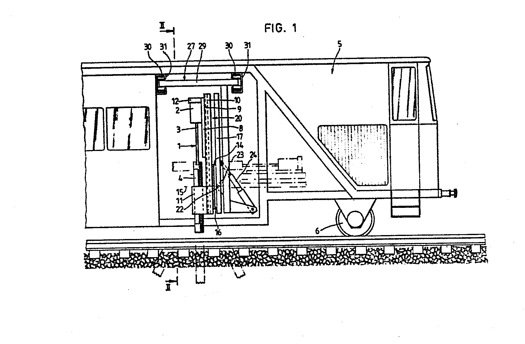
Description
Insbesondere auch im Hinblick auf die Vergrösserung der Geschwindigkeit von Eisenbahnzügen sowie der Last pro Achse, hat sich in neuester Zeit das Bedürfnis gezeigt, eine Reihe von Angaben über den Zustand und die Zusammensetzung des Gleisunterbaues zu erhalten, wobei unter Gleisunterbau nicht nur der unmittelbar unter den Schienen liegende Schotter, sondern ebenfalls der Untergrund, d.h. die Auflagefläche dieses Schotters, verstanden werden soll.Particularly with regard to the increase in the speed of railroad trains and the load per axle, there has recently been a need to obtain a number of details about the condition and composition of the track substructure, whereby under track substructure not only that directly under the Railroad gravel, but also the underground, ie the bearing surface of this ballast should be understood.
Nur im Sinne von Beispielsangaben interessiert aus den eingangs genannten Gründen hinsichtlich des Schotters u.a. die Kornzusammensetzung und der Verschmutzungsgrad, während im Zusammenhang mit dem Untergrund u.a. das Traglastverhalten, der Feuchtigkeitsgehalt und die Kornzusammensetzung der betr. Erdschichten im Vordergrund stehen.Only in the sense of example information is interested in the ballast, among other things, for the reasons mentioned above. the grain composition and the degree of soiling, while in connection with the surface i.a. the load behavior, the moisture content and the grain composition of the respective layers of earth are in the foreground.
Da eventuell notwendige Sanierungsmassnahmen, sei es hinsichtlich des Schotters oder des Untergrundes, mit erheblichen Umtrieben und Aufwendungen verbunden ist, besteht ein eminentes Interesse, über die bereits erwähnten Kriterien und gegebenenfalls noch weitere möglichst genaue Aufschlüsse zu erhalten.Since any necessary remedial measures, be it with regard to the ballast or the subsoil, are associated with considerable activities and expenses, there is an eminent interest in the criteria already mentioned and, if applicable to obtain further information as precise as possible.
Das Bedürfnis, durch geeignete Untersuchungen nähere Angaben in bezug auf die wesentlichsten Kriterien zu erhalten, ist an sich nicht neu. Bekannt sind vor allem zwei Verfahren. Das eine besteht darin, den Schotter zwischen zwei benachbarten Schwellen von Hand oder mechanisch auszuräumen, um sich dann sowohl hinsichtlich des Schotters als auch des Untergrundes von Auge ein sehr ungefähres Urteil über den Zustand des Unterbaues zu machen. Es ist klar, dass diese Methode sehr arbeitsaufwendig ist, und dies insbesondere auch darum, weil der ausgeräumte Schotter wieder eingefüllt werden muss. Des weiteren können die Beobachtungsresultate durch Witterungseinflüsse (z.B. Regen) völlig verfälscht werden. Schliesslich kann bei der üblichen Methode nach dem Wiedereinfüllen des Schotters eine Beeinträchtigung der Lagestabilität nicht ausgeschlossen werden. Entscheidend ist aber, dass keine Möglichkeit bestand, mit diesem bis anhin verwendeten Verfahren genügend genaue Aufschlüsse über die Beschaffenheit des Schotterbettes und des Untergrundes zu erhalten, die als solche gestattet hätten, gezielte und wirksame Sanierungsmassnahmen zu treffen.The need to obtain more detailed information on the most important criteria through suitable studies is not new in itself. Above all, two methods are known. One is to clear the ballast between two neighboring sleepers by hand or mechanically in order to then make a very approximate assessment of the condition of the substructure with regard to both the ballast and the subsoil. It is clear that this method is very labor-intensive, especially because the cleared gravel has to be refilled. Furthermore, the observation results can be completely falsified by weather influences (e.g. rain). Finally, an impairment of the position stability cannot be ruled out with the usual method after refilling the ballast. It is crucial, however, that there was no way to obtain sufficiently precise information about the nature of the ballast bed and the subsoil with this method that had been used up to now, which as such would have allowed targeted and effective remedial measures to be taken.
Eine zweite vorbekannte Methode besteht darin, einen Schürfschlitz im Schotterbett herzustellen und in den Untergrund mit vorbestimmter Geschwindigkeit einen Dorn einzutreiben. Aufgrund der für diesen Eintrieb notwendigen Kraft kann dann im Hinblick auf gewisse mathematische Zusammenhänge auf das Traglastverhalten des Untergrundes geschlossen werden. Diese Methode besitzt den entscheidenden Nachteil, dass nur gerade das Traglastverhalten, und auch dieses nur mit angenäherter Genauigkeit, festgestellt werden kann, während in bezug auf alle anderen Kriterien, wie z.B. die Kornzusammensetzung und der Verschmutzungsgrad des Schotters sowie die Kornzusammensetzung der Erdschichten und deren Feuchtigkeitsgehalt, keine weiteren Angaben erhältlich sind.A second known method consists in producing a digging slot in the ballast bed and driving a mandrel into the ground at a predetermined speed. Based on the force required for this drive, the load capacity behavior of the subsoil can then be concluded with regard to certain mathematical relationships. This method has the decisive disadvantage that only the payload behavior and this can only be determined with approximate accuracy, while in relation to all other criteria, such as the grain composition and the degree of contamination of the ballast as well the grain composition of the layers of earth and their moisture content, no further information is available.
Der vorliegenden Erfindung liegt nun die Aufgabe zugrunde, ein witterungsunabhängiges Verfahren und eine zur Durchführung dieses Verfahrens geeignete Einrichtung zu schaffen, welches Verfahren zur Gewinnung von Bodenproben im Bereiche von Bahngleisen zum Zwecke der Ermittlung von bodenmechanischen Kennwerten geeignet ist und gegenüber den vorbekannten Verfahren den entscheidenden Vorteil besitzt, dass es weniger arbeitsaufwendig ist, auch bei eingleisigen Anlagen den durchgehenden Zugsverkehr nicht behindert und vor allem wesentlich mehr Angaben über die Beschaffenheit des Schotters und des Untergrundes liefert, d.h. beispielsweise Angaben über die Kornzusammensetzung und den Verschmutzungsgrad des Schotters, das Traglastverhalten des Unterbaues, die Kornzusammensetzung der Erdschichten und den Feuchtigkeitsgehalt, um für den Bau bzw. die Sanierung relevante Daten betreffend die Art und den Umfang der zu ergreifenen Massnahmen zu gewinnen.The present invention is based on the object of creating a weather-independent method and a device suitable for carrying out this method, which method is suitable for obtaining soil samples in the area of railway tracks for the purpose of determining soil mechanical parameters and the decisive advantage over the previously known methods has that it is less labor-intensive, does not hinder continuous train traffic even with single-track systems and, above all, provides considerably more information about the quality of the ballast and the sub-surface, ie For example, information about the grain composition and the degree of contamination of the ballast, the load-bearing behavior of the substructure, the grain composition of the layers of earth and the moisture content in order to obtain relevant data for the construction or renovation regarding the type and scope of the measures to be taken.
Diese Aufgaben werden durch ein Verfahren der eingangs genannten Art gelöst, welches dadurch gekennzeichnet ist, dass mittels eines Bohrgerätes im Bereiche von Gleisanlagen Erdbohrungen vorgenommen und Bohrkerne gewonnen werden, welche letzten dann als Prüflinge für labortechnische Untersuchungen dienen können.These tasks are solved by a method of the type mentioned at the outset, which is characterized in that earth bores are made in the area of track systems by means of a drilling device and drilling cores are obtained, which can then serve as test objects for laboratory tests.
Zur Durchführung dieses Verfahrens besonders geeignet ist eine Einrichtung, welche dadurch gekennzeichnet ist, dass das Bohrgerät auf einem Eisenbahnwagen montiert ist.A device which is characterized in that the drilling device is mounted on a railroad car is particularly suitable for carrying out this method.
In der folgenden Beschreibung ist eine beispielsweise Ausführungsart des betreffenden Verfahrens erläutert, und in der Zeichnung sind zwei beispielsweise Ausführungsformen sowie gewisse konstruktive Einzelheiten z.T. schematisch dargestellt.
- Fig. 1 eine schematische Seitenansicht einer in einen Eisenbahnwagen eingebauten ersten Ausführungsform unter Weglassung eines Zylinder-Kolben-Aggregates,
- Fig. 2 einen Schnitt nach der Linie II-II in Fig. 1,
- Fig. 3 eine schematische Seitenansicht einer zweiten, auf einem Eisenbahnwagen aufgebauten Ausführungsform,
- Fig. 4 eine Ansicht in Richtung des Pfeiles A in Fig. 3,
- Fig. 5 eine Draufsicht.
- Fig. 6 und 7 sind schematische Darstellungen verschiedener Arbeitsstellungen des Bohraggregates.
- Fig. 8 zeigt das Mitnehmerende des Bohrrohres samt Mitnehmer in perspektivischer Darstellung bei teilweise weggelassener Deckplatte,
- Fig. 9 einen Axialschnitt durch eine besondere Ausführungsform des Bohrzylinders und
- Fig. 10 einen Schnitt nach der Linie X-X in Fig. 9.
- 1 is a schematic side view of a first embodiment installed in a railroad car, with the omission of a cylinder-piston unit,
- 2 shows a section along the line II-II in FIG. 1,
- 3 is a schematic side view of a second embodiment built on a railway carriage,
- 4 is a view in the direction of arrow A in FIG. 3,
- Fig. 5 is a plan view.
- 6 and 7 are schematic representations of various working positions of the drilling unit.
- 8 shows the driver end of the drill pipe together with the driver in a perspective view with the cover plate partially omitted,
- Fig. 9 is an axial section through a special embodiment of the drilling cylinder and
- 10 shows a section along the line XX in FIG. 9.
Beim Ausführungsbeispiel gemäss Fig. 1 und 2 sind zwei generell mit 1 bezeichnete Erdbohraggregate vorgesehen, deren wesentliche Teile ein Antriebsmotor 2, eine Uebertragungswelle 3 und ein vom Motor her über die Welle 3 angetriebenes Bohrrohr 4 sind. Auf noch zu beschreibende Weise sind beim dargestellten Ausführungebeispiel gemäss Fig. 1 und 2 zwei identische Erdbohraggregate 1 vorgesehen, wobei aber durchaus auch die Möglichkeit bestünde, sich mit einem einzigen solchen Aggregat zu begnügen.1 and 2, two earth drilling units, generally designated 1, are provided, the essential parts of which are a
Die beiden in Fig. 1 und 2 dargestellten Zwillingsaggregate 1 sind auf noch zu beschreibende Weise in einem Teil eines Eisenbahnwagens 5, der vermittels Rädern 6 auf Schienen 7 fahrbar ist, rechtwinklig zur Gleisachse verschiebbar angeordnet. Die übrigen Teile des Eisenbahnwagens 5 können auf beliebige Weise ausgestaltet sein. So wäre es möglich, einen Aufenthaltsraum für die Bedienungsmannschaft, einen Materialraum sowie ein Abteil für die Bohrkerne vorzusehen.The two twin units 1 shown in FIGS. 1 and 2 are arranged in a manner to be described in a part of a
Der Einfachheit halber bezieht sich die folgende Beschreibung auf eines der beiden Zwillingserdbohraggregate 1, da diese beiden Aggregate in identischer Weise aufgebaut und eingebaut sind. Jedes der betr. Aggregate ist auf je einem Schlitten 8 befestigt, der in entsprechenden Führungen 9 einer Schwenkplatte 10 läuft. Beim dargestellten Ausführungsbeispiel ist nur der Motor 2 mit dem Schlitten 8 fest verbunden, während das Bohrrohr 4 innerhalb des ebenfalls auf der Schwenkplatte 10 befestigten Klobens 11 gleitbar gelagert ist. Es würde aber auch die Möglichkeit bestehen, dem Bohrrohr 4 einen Schlitten zuzuordnen. Oben am Schlitten 8 ist die Betätigungsplatte 12 vorgesehen, an welcher die Zylinder-Kolben-Aggregate 13 angreifen, vermittels welcher der Schlitten 8 samt dem Erdbohraggregat 1 längs der Schwenkplatte 10 (in der dargestellten Ausgangslage rechtwinklig zur Gleisebene) bewegt werden kann.For the sake of simplicity, the following description refers to one of the two twin earth drilling units 1, since these two units are constructed and installed in an identical manner. Each of the units concerned is attached to a
Mit der Schwenkplatte 10 fest verbunden ist die eine Rasterplatte 14, welche zusammen mit der Schwenkplatte 10 und dem Bohraggregat 1 um die geometrische Achse 15 schwenkbar ist. Mit der Rasterplatte 14 arbeitet die Rasterplatte 16 zusammen, welche ihrerseits fest mit dem Rahmenteil 17 verbunden ist, der zusammen mit dem weiteren Rahmenteil 18 sowie dem Querbalken 19 den Rahmen 20 bildet.With the
Um die Zeichnung nicht zu überlasten, sind die Einzelheiten der beiden Rasterplatten 14 und 16 in der Zeichnung nicht dargestellt. So besitzt von den beiden Rasterplatten die eine federnd vorstehende Teile, welche in entsprechende Ausnehmungen der andern Rasterplatte eintreten können. Des weiteren sind an der Schwenkplatte 10 befestigte, nicht dargestellte Bedienungsteile vorgesehen, mit welchen die Schwenkplatte samt dem Bohraggregat um die Achse 15 entsprechend der Rasterteilung der beiden Rastscheiben 14 und 16 verschwenkt werden kann.In order not to overload the drawing, the details of the two
Zwischen den beiden Rahmenteilen 17 und 18 und einem festen Teil des Eisenbahnwagens ist je ein Zylinder-Kolben-Aggregat 21 angeordnet. Des weiteren besitzt jeder Rahmenteil 17 und 18 einen seitlich abstehenden Zapfen 22, welche Zapfen in entsprechende Laschen 23 der einen Säule 24 (die andere ist mit 25 bezeichnet) eines Hauptrahmens 26 eintreten, so dass die Schwenkplatte 10 mittels der beiden Zylinder-Kolben-Aggregate 21 um die geometrische Achse der Lagerzapfen 22 verschwenkt werden kann.A cylinder-piston unit 21 is arranged between the two
Der Hauptrahmen 26 ist am Verschieberahmen 27 aufgehängt, der im wesentlichen aus zwei Längsholmen 28 (in der Zeichnung ist nur einer sichtbar) und zwei Querholmen 29 besteht. Beide Längsholme 28 laufen in je einer mit Wälzrollen 30 ausgerüsteten und quer zur Gleisachse angeordneten U-Schienen 3, so dass der Verschieberahmen 27 samt allen daran befestigten Teilen, wie beispielsweise den beiden Zwillingserdbohraggregaten 1, rechtwinklig zur Gleisachse hin und her verschoben werden kann.The main frame 26 is suspended from the sliding
Wenn, wie im dargestellten Ausführungsbeispiel, die beiden Zwillingserdbohraggregate 1 innerhalb der beiden Schienen 7 angeordnet sind, so gestattet die beschriebene Verschiebungsmöglichkeit, den Verschieberahmen 27 so zu bewegen, dass sich ein Erdbohraggregat 1 ungefähr in der Mitte zwischen den beiden Schienen 7 befindet, während das andere ausserhalb des Eisenbahnwagenprofiles und damit auch ausserhalb des Gleises zu liegen kommt, so dass simultan sowohl zwischen den beiden Schienen 7 als auch ausserhalb des Gleises Bohrungen vorgenommen werden können.If, as in the illustrated embodiment, the two twin earth drilling units 1 are arranged within the two rails 7, the described displacement option allows the sliding
Die Bohrkerne können dann entweder im Eisenbahnwagen selber labortechnisch untersucht, oder aber an eine geeignete Stelle transportiert werden. Wie bereits erwähnt, dienen dann diese Bohrkerne zur Gewinnung von bodenmechanischen Erkenntnissen.The drill cores can then either be examined in the laboratory itself in the laboratory, or on a suitable place to be transported. As already mentioned, these drill cores then serve to obtain soil mechanics knowledge.
In den Fig. 3-7 ist schematisch eine weitere Aus-. führungsform des Erfindungsgegenstandes dargestellt, wobei insbesondere hinsichtlich der Mittel zur Bewegung (Verdrehung und Verschwenkung) des Erdbohraggregates 1 auf die in den Fig. 1 und 2 dargestellte konstruktive Möglichkeit verwiesen wird.3-7 schematically shows a further off. management form of the subject matter of the invention, wherein reference is made in particular with regard to the means for movement (rotation and pivoting) of the earth drilling unit 1 to the constructive option shown in FIGS. 1 and 2.
Beim betreffenden Ausführungsbeispiel ist am einen Ende eines Eisenbahnwagens 5 eine Grundplatte 32 vorgesehen, welche fest mit einem Zahnrad 33 verbunden ist. Dieses Zahnrad 33 kann vermittels eines mit ihm kämmenden Ritzels 34 in Umlauf versetzt werden, wobei das betreffende Ritzel mit irgendwelchen Bedienungsmitteln versehen ist. An ihrem dem Wagenende zugewendeten Rand besitzt die Grundplatte 32 zwei Laschen, durch welche, wie ebenfalls durch solche (39) der Schwenkplatte 37, die Schwenkachse 36 durchtritt. Dabei ist die Lage der Schwenkachse 36 so gewählt, dass, wenn die um diese Achse drehbare Schwenkplatte 37 rechtwinklig zur Gleisebene aufgestellt ist, das auf dieser Schwenkplatte 37 verschiebbar gelagerte Erdbohraggregat 1 über das Wagenende hinauskragt.In the exemplary embodiment in question, a
Zwischen der Grundplatte 32 und der Schwenkplatte 37 sind seitlich der Schwenkplatte 37 zwei Zylinder-Kolben-Aggregate 38 vorgesehen, mittels welchen die Schwenkplatte 37 und damit das Erdbohraggregat 1 gegenüber der durch die Grundplatte 32 gegebenen Ebene verschwenkt werden kann.Between the
Die Schwenkplatte 37 ist, wie beim ersten Ausführungsbeispiel, über zwei Rastscheiben mit dem Rahmen 39 verbunden, welcher letzte mittels des Zylinder-Kolben-Aggregates 38 um die Achse 36 verschwenkt werden kann.As in the first exemplary embodiment, the
Von den Rastplatten 40 und 41 ist, entsprechend der konstruktiven Lösung beim ersten Ausführungsbeispiel, die eine (40) mit der Schwenkplatte 37 und die andere (41) mit dem Rahmen 39 fest verbunden. Von diesen Platten 40 und 41 weist wie üblich die eine nicht dargestellte federnde, vorstehende Rastmittel auf, welche dazu bestimmt und geeignet sind, in entsprechende Ausnehmungen der andern Rastplatte einzugreifen.Of the locking plates 40 and 41 is, accordingly the constructive solution in the first embodiment, one (40) with the
Wie beim Ausführungsbeispiel gemäss Fig. 1 und 2 besitzt die Schwenkplatte 37 auf ihrer Aussenseite eine Führung für einen Schlitten 42, auf welchem letzten das Erdbohraggregat 1 befestigt ist. Dieser Schlitten, der dank der erwähnten Führungen parallel zur Achse der Schwenkplatte 37 auf dieser letzten verschiebbar angeordnet ist, besitzt einen Betätigungsfortsatz 43, an welchem seitlich je ein nicht dargestelltes Zylinder-Kolben-Aggregat angreift, vermittels dessen das Erdbohraggregat 1 längs der Führung von der in Fig. 3 dargestellten Stellung rechtwinklig zur Gleisebene in eine Entnahmestellung parallel zu dieser Ebene gebracht werden kann.As in the exemplary embodiment according to FIGS. 1 and 2, the
Dank der Rastplatten 40 und 41 besteht weiterhin die Möglichkeit, das Erdbohraggregat gegenüber der Senkrechten zur Gleisebene in eine frei wählbare Zwischenstellung zu bringen, so dass grundsätzlich Bohrproben nicht nur in schräger Richtung ausserhalb des Gleises, sondern auch von der Auflage ummittelbar unter den Schwellen 44 entnommen werden können. Diese Belange sind schematisch in den Fig. 6 und 7 dargestellt.Thanks to the locking plates 40 and 41, there is still the possibility of placing the earth drilling unit in a freely selectable intermediate position opposite the vertical to the track level, so that drilling samples are taken not only in an oblique direction outside the track, but also directly from the support underneath the
Vom ersten Ausführungsbeispiel unterscheidet sich das in den Figuren 3-7 dargestellte vor allem dadurch, dass das Zwillingserdbohraggregat gemäss dem ersten Ausführungsbeispiel durch ein einzelnes Erdbohraggregat ersetzt ist, und dass anstelle der beim ersten Ausführungsbeispiel vorgesehenen Verschiebbarkeit der Zwillingserdbohraggregate ein einzelnes solches Aggregat am Ende eines Eisenbahnwagens auf einer verdrehbaren Platte 32 angeordnet ist.The first embodiment differs from that shown in FIGS. 3-7 in that the twin earth drilling unit according to the first embodiment is replaced by a single earth drilling unit, and that instead of the displaceability of the twin earth drilling units provided in the first embodiment, a single such unit at the end of a railroad car on egg ner
Wie bereits erwähnt, geht es bei der betreffenden Einrichtung darum, an gewissen Stellen im Bereiche eines Eisenbahngleises Bohrproben zu entnehmen, die dann einer labortechnischen Untersuchung unterworfen werden können. Bei einer zweckmässigen Ausführungsform dieser Einrichtung ist darauf Bedacht genommen, dass die Bohrkerne auf möglichst einfache Art und Weise dem Bohrrohr entnommen werden können.As already mentioned, the facility in question is concerned with taking drill samples at certain points in the area of a railway track, which can then be subjected to a laboratory test. In an expedient embodiment of this device, care is taken to ensure that the drill cores can be removed from the drill pipe in the simplest possible manner.
Biezu dient bereits die bei beiden Ausführungsbeispielen vorgesehene Möglichkeit der Verschwenkung des Bohrrohres in eine horizontale Ebene, was im Hinblick auf eine weitere beispielsweise Ausführungsform des Bohrrohres die Entnahme der Bohrkerne entscheidend vereinfacht.The possibility of pivoting the drill pipe into a horizontal plane, which is provided in both exemplary embodiments, already serves this purpose, which decisively simplifies the removal of the drill cores with regard to a further exemplary embodiment of the drill pipe.
So besitzt das Bohrrohr ein sich über die Länge eines normalen Bohrkernes erstreckendes und über den halben Umfang reichendes Fenster 45, welches bei verschwenktem Bohrrohr nach oben gedreht und geöffnet wird, so dass der Bohrkern ohne weiteres entnommen werden kann. In Fig. 8 ist eine beispielsweise Ausführungsform eines solchen Bohrrohres dargestellt. Dabei ist mit 46 der vom Motor angetriebene Mitnehmer bezeichnet, der in entsprechende T-förmige Nuten 47 des Bohrrohres 4 eintritt. Diese Ausgestaltung des Mitnehmers 46 und des Bohrrohroberteils gestattet nicht nur Drehbewegungen, sondern auch die Uebertragung einer axialen Kraft, wie sie beispielsweise beim Herausziehen des Bohrrohres aus dem Bohrloch aufgewendet werden muss.For example, the drill pipe has a
Aus Fig. 8 ergibt sich weiter die Grösse des Fensters, dessen Anordnung in Richtung der geometrischen Achse des Bohrrohres 4 der Länge eines üblichen Bohrkernes entspricht, und welches sich über den halben Bohrrohrumfang erstreckt. Während des Bohrvorganges ist das Fenster 45 durch die Platte 48 überdeckt, welche in Fig. 8 zur Erleichterung des Verständnisses teilweise weggelassen ist. Der seitliche Fensterrand sowie der mit ihm zusammenarbeitende Plattenrand besitzen entsprechende Absetzungen, während längs des Unterrandes der Plattenrand mit einer vorstehenden Rippe 49 den Fensterrand untergreift. Der Oberrand der Platte ist mittels auf der Zeichnung nicht ersichtlichen, versenkten Schrauben mit einem Verstärkungsring 50 verbunden, so dass die Platte 48 während des Bohrvorganges einen Abschluss des Fensters 45 bildet, ohne dass durch radial vorstehende Teile einer Drehbewegung ein zusätzlicher Widerstand entgegengesetzt würde.8 also shows the size of the window, the arrangement of which corresponds to the length of a conventional drill core in the direction of the geometric axis of the
Eine weitere Möglichkeit der Ausbildung des Bohrrohres 4 ist in den Fig. 9 und 10 dargestellt und besteht darin, dass der Mantel des Bohrrohres 4 geschlitzt ist. Durch den Schlitz 51 kann demzufolge eine Grobbeurteilung der verschiedenen Zonen vorgenommen werden, wobei dieser Schlitz 51 noch zusätzlich gestattet, seitlich kleinere Bohrrohre 52 einzuführen, um an bestimmten Stellen dem Bohrkern Bodenproben entnehmen zu können.Another possibility for the formation of the
Auf diese Weise gelingt es, Bodenproben im Bereiche von Bahngleisen zum Zwecke der Ermittlung von bodenmechanischen Kennwerten zu entnehmen, welche eine Vielzahl von wesentlichen Angaben vermitteln, ohne dass die Nachteile der bisher bekannten Verfahren in Kauf genommen werden müssten.In this way it is possible to take soil samples in the area of train tracks for the purpose of determining soil mechanical parameters, which convey a large number of essential information without having to accept the disadvantages of the previously known methods.
Des weiteren gestattet die ebenfalls Gegenstand der Erfindung bildende Einrichtung, auf einfache und arbeitssparende Art und Weise diese Bodenproben zu gewinnen.Furthermore, the device also forming the subject of the invention allows these soil samples to be obtained in a simple and labor-saving manner.
Claims (6)
Priority Applications (1)
| Application Number | Priority Date | Filing Date | Title |
|---|---|---|---|
| AT83200715T ATE24561T1 (en) | 1982-05-26 | 1983-05-20 | DEVICE FOR TAKING SOIL SAMPLES IN THE AREAS OF RAILWAY TRACKS FOR THE PURPOSE OF DETERMINING SOIL MECHANICAL DATA. |
Applications Claiming Priority (2)
| Application Number | Priority Date | Filing Date | Title |
|---|---|---|---|
| CH3240/82 | 1982-05-26 | ||
| CH324082 | 1982-05-26 |
Publications (3)
| Publication Number | Publication Date |
|---|---|
| EP0096431A2 true EP0096431A2 (en) | 1983-12-21 |
| EP0096431A3 EP0096431A3 (en) | 1984-12-19 |
| EP0096431B1 EP0096431B1 (en) | 1986-12-30 |
Family
ID=4251678
Family Applications (1)
| Application Number | Title | Priority Date | Filing Date |
|---|---|---|---|
| EP83200715A Expired EP0096431B1 (en) | 1982-05-26 | 1983-05-20 | Apparatus for obtaining soil samples in the neighbourhood of railroad tracks with the aim to explore the mechanical properties of the soil |
Country Status (3)
| Country | Link |
|---|---|
| EP (1) | EP0096431B1 (en) |
| AT (1) | ATE24561T1 (en) |
| DE (1) | DE3368707D1 (en) |
Cited By (3)
| Publication number | Priority date | Publication date | Assignee | Title |
|---|---|---|---|---|
| FR2641753A1 (en) * | 1989-01-18 | 1990-07-20 | Sefi | Railway ground-compacting vehicle |
| EP0844331A1 (en) * | 1996-11-25 | 1998-05-27 | Folke Söderberg | Power transmission device for a drill for obtaining soil samples |
| WO2021061344A1 (en) * | 2019-09-25 | 2021-04-01 | Bnsf Railway Company | System and method for confining ballast samples |
Family Cites Families (5)
| Publication number | Priority date | Publication date | Assignee | Title |
|---|---|---|---|---|
| FR906796A (en) * | 1944-08-17 | 1946-01-18 | Mobile device for working the soil and the execution of adjoining structures, as well as for measuring their resistance | |
| FR1142380A (en) * | 1954-06-01 | 1957-09-17 | Hands England Oilfields Equipm | Rotary drilling rig |
| FR2271343B1 (en) * | 1974-01-29 | 1976-10-08 | Fondasol Tech | |
| US4316393A (en) * | 1980-06-04 | 1982-02-23 | Harry Philipenko | Soil sampler and mounting arrangement |
| DE3034704C2 (en) * | 1980-09-15 | 1982-10-28 | Hermann-Dieter Dr. 4300 Essen Koehne | Rail vehicle for track body work |
-
1983
- 1983-05-20 DE DE8383200715T patent/DE3368707D1/en not_active Expired
- 1983-05-20 AT AT83200715T patent/ATE24561T1/en not_active IP Right Cessation
- 1983-05-20 EP EP83200715A patent/EP0096431B1/en not_active Expired
Cited By (12)
| Publication number | Priority date | Publication date | Assignee | Title |
|---|---|---|---|---|
| FR2641753A1 (en) * | 1989-01-18 | 1990-07-20 | Sefi | Railway ground-compacting vehicle |
| EP0844331A1 (en) * | 1996-11-25 | 1998-05-27 | Folke Söderberg | Power transmission device for a drill for obtaining soil samples |
| WO2021061344A1 (en) * | 2019-09-25 | 2021-04-01 | Bnsf Railway Company | System and method for confining ballast samples |
| US11199478B2 (en) | 2019-09-25 | 2021-12-14 | Bnsf Railway Company | Systems and methods for confining ballast samples |
| KR20220059959A (en) * | 2019-09-25 | 2022-05-10 | 비엔에스에프 레일웨이 컴퍼니 | Systems and Methods for Confining Ballast Samples |
| CN114761638A (en) * | 2019-09-25 | 2022-07-15 | 北伯林顿铁路公司 | System and method for confining ballast samples |
| JP2022550687A (en) * | 2019-09-25 | 2022-12-05 | ビーエヌエスエフ レイルウェイ カンパニー | System and method for restraining ballast samples |
| JP2024020543A (en) * | 2019-09-25 | 2024-02-14 | ビーエヌエスエフ レイルウェイ カンパニー | Systems and methods for restraining ballast samples |
| CN114761638B (en) * | 2019-09-25 | 2024-06-04 | 北伯林顿铁路公司 | System and method for limiting ballast samples |
| US12000762B2 (en) | 2019-09-25 | 2024-06-04 | Bnsf Railway Company | Systems and methods for confining ballast samples |
| JP7614305B2 (en) | 2019-09-25 | 2025-01-15 | ビーエヌエスエフ レイルウェイ カンパニー | Systems and methods for restraining ballast samples - Patents.com |
| AU2020352424B2 (en) * | 2019-09-25 | 2026-01-22 | Bnsf Railway Company | System and method for confining ballast samples |
Also Published As
| Publication number | Publication date |
|---|---|
| EP0096431A3 (en) | 1984-12-19 |
| EP0096431B1 (en) | 1986-12-30 |
| ATE24561T1 (en) | 1987-01-15 |
| DE3368707D1 (en) | 1987-02-05 |
Similar Documents
| Publication | Publication Date | Title |
|---|---|---|
| DE4402464C1 (en) | Horizontal sliding window with at least one sliding sash which can be moved transversely with respect to the frame plane | |
| DE68919206T2 (en) | SELF-DRIVING DEVICE FOR CONCRETE TRENCHES. | |
| EP0391149B1 (en) | Portable bridge and system for placing the bridge | |
| DE1271369B (en) | Device for parking motor vehicles or the like. | |
| DE2840408B1 (en) | Device for determining a relative mobility between parts of the chassis or the steering in a vehicle | |
| DE2047480A1 (en) | Crawler crane with adjustable track width | |
| DE806859C (en) | Connecting bridge between two railroad cars | |
| EP0139959A2 (en) | Rotary cutter | |
| EP3045638B1 (en) | Sliding and rotating leaf system | |
| DE2421964A1 (en) | EXPANSION JOINT | |
| DE2733419A1 (en) | Wet concrete consolidating and smoothing device - has height adjustable rotary plate linked to carriage on transverse guide | |
| EP0690176B1 (en) | Chain of divider modules | |
| EP0008082B1 (en) | Garage for parking vehicles one above the other | |
| EP0096431B1 (en) | Apparatus for obtaining soil samples in the neighbourhood of railroad tracks with the aim to explore the mechanical properties of the soil | |
| DE3143321C2 (en) | ||
| DE3619677C1 (en) | Device for lifting and lowering the head and foot sections of a bed frame | |
| DE3034704A1 (en) | RAIL VEHICLE FOR TRACKED WORK | |
| DE1459634B1 (en) | Switch for two-lane suspension railway vehicles | |
| DE2523291C3 (en) | Guardrail section set up to open | |
| DE19531952A1 (en) | Joint cutter for concrete roadway surfaces | |
| DE655748C (en) | Movable sliding platform for conveyor wagons in the mine | |
| DE2708453C3 (en) | Box body for vehicles with at least one sliding door | |
| DE4437955A1 (en) | Rail track permanent way | |
| DE69611923T2 (en) | Roller device for railway switches | |
| DE3420210A1 (en) | Device for laying and/or levelling cross-country ski runs |
Legal Events
| Date | Code | Title | Description |
|---|---|---|---|
| PUAI | Public reference made under article 153(3) epc to a published international application that has entered the european phase |
Free format text: ORIGINAL CODE: 0009012 |
|
| AK | Designated contracting states |
Designated state(s): AT BE CH DE FR GB IT LI LU NL SE |
|
| PUAL | Search report despatched |
Free format text: ORIGINAL CODE: 0009013 |
|
| AK | Designated contracting states |
Designated state(s): AT BE CH DE FR GB IT LI LU NL SE |
|
| 17P | Request for examination filed |
Effective date: 19850607 |
|
| GRAA | (expected) grant |
Free format text: ORIGINAL CODE: 0009210 |
|
| AK | Designated contracting states |
Kind code of ref document: B1 Designated state(s): AT BE CH DE FR GB IT LI LU NL SE |
|
| REF | Corresponds to: |
Ref document number: 24561 Country of ref document: AT Date of ref document: 19870115 Kind code of ref document: T |
|
| REF | Corresponds to: |
Ref document number: 3368707 Country of ref document: DE Date of ref document: 19870205 |
|
| ITF | It: translation for a ep patent filed | ||
| ET | Fr: translation filed | ||
| PLBE | No opposition filed within time limit |
Free format text: ORIGINAL CODE: 0009261 |
|
| STAA | Information on the status of an ep patent application or granted ep patent |
Free format text: STATUS: NO OPPOSITION FILED WITHIN TIME LIMIT |
|
| 26N | No opposition filed | ||
| PGFP | Annual fee paid to national office [announced via postgrant information from national office to epo] |
Ref country code: SE Payment date: 19890329 Year of fee payment: 7 |
|
| PGFP | Annual fee paid to national office [announced via postgrant information from national office to epo] |
Ref country code: GB Payment date: 19890430 Year of fee payment: 7 |
|
| PG25 | Lapsed in a contracting state [announced via postgrant information from national office to epo] |
Ref country code: GB Effective date: 19900520 |
|
| PG25 | Lapsed in a contracting state [announced via postgrant information from national office to epo] |
Ref country code: SE Effective date: 19900521 |
|
| GBPC | Gb: european patent ceased through non-payment of renewal fee | ||
| EPTA | Lu: last paid annual fee | ||
| EUG | Se: european patent has lapsed |
Ref document number: 83200715.7 Effective date: 19910115 |
|
| PGFP | Annual fee paid to national office [announced via postgrant information from national office to epo] |
Ref country code: LU Payment date: 19970702 Year of fee payment: 15 |
|
| PGFP | Annual fee paid to national office [announced via postgrant information from national office to epo] |
Ref country code: FR Payment date: 19980409 Year of fee payment: 16 |
|
| PGFP | Annual fee paid to national office [announced via postgrant information from national office to epo] |
Ref country code: NL Payment date: 19980430 Year of fee payment: 16 |
|
| PGFP | Annual fee paid to national office [announced via postgrant information from national office to epo] |
Ref country code: CH Payment date: 19980512 Year of fee payment: 16 Ref country code: BE Payment date: 19980512 Year of fee payment: 16 |
|
| PG25 | Lapsed in a contracting state [announced via postgrant information from national office to epo] |
Ref country code: LU Free format text: LAPSE BECAUSE OF NON-PAYMENT OF DUE FEES Effective date: 19980520 |
|
| PGFP | Annual fee paid to national office [announced via postgrant information from national office to epo] |
Ref country code: AT Payment date: 19990415 Year of fee payment: 17 |
|
| PG25 | Lapsed in a contracting state [announced via postgrant information from national office to epo] |
Ref country code: LI Free format text: LAPSE BECAUSE OF NON-PAYMENT OF DUE FEES Effective date: 19990531 Ref country code: CH Free format text: LAPSE BECAUSE OF NON-PAYMENT OF DUE FEES Effective date: 19990531 Ref country code: BE Free format text: LAPSE BECAUSE OF NON-PAYMENT OF DUE FEES Effective date: 19990531 |
|
| BERE | Be: lapsed |
Owner name: HCH HEINRICH GRONAU A.G. Effective date: 19990531 |
|
| PG25 | Lapsed in a contracting state [announced via postgrant information from national office to epo] |
Ref country code: NL Free format text: LAPSE BECAUSE OF NON-PAYMENT OF DUE FEES Effective date: 19991201 |
|
| REG | Reference to a national code |
Ref country code: CH Ref legal event code: PL |
|
| PG25 | Lapsed in a contracting state [announced via postgrant information from national office to epo] |
Ref country code: FR Free format text: LAPSE BECAUSE OF NON-PAYMENT OF DUE FEES Effective date: 20000131 |
|
| NLV4 | Nl: lapsed or anulled due to non-payment of the annual fee |
Effective date: 19991201 |
|
| REG | Reference to a national code |
Ref country code: FR Ref legal event code: ST |
|
| PG25 | Lapsed in a contracting state [announced via postgrant information from national office to epo] |
Ref country code: AT Free format text: LAPSE BECAUSE OF NON-PAYMENT OF DUE FEES Effective date: 20000520 |
|
| PGFP | Annual fee paid to national office [announced via postgrant information from national office to epo] |
Ref country code: DE Payment date: 20021119 Year of fee payment: 20 |