EP0096431B1 - Dispositif pour l'obtention d'echantillons de sol aux abords de voies de chemin de fer dans le but d'explorer des caractéristiques mécaniques du sol - Google Patents
Dispositif pour l'obtention d'echantillons de sol aux abords de voies de chemin de fer dans le but d'explorer des caractéristiques mécaniques du sol Download PDFInfo
- Publication number
- EP0096431B1 EP0096431B1 EP83200715A EP83200715A EP0096431B1 EP 0096431 B1 EP0096431 B1 EP 0096431B1 EP 83200715 A EP83200715 A EP 83200715A EP 83200715 A EP83200715 A EP 83200715A EP 0096431 B1 EP0096431 B1 EP 0096431B1
- Authority
- EP
- European Patent Office
- Prior art keywords
- soil
- track
- drilling tool
- plate
- neighbourhood
- Prior art date
- Legal status (The legal status is an assumption and is not a legal conclusion. Google has not performed a legal analysis and makes no representation as to the accuracy of the status listed.)
- Expired
Links
Images



Classifications
-
- E—FIXED CONSTRUCTIONS
- E01—CONSTRUCTION OF ROADS, RAILWAYS, OR BRIDGES
- E01B—PERMANENT WAY; PERMANENT-WAY TOOLS; MACHINES FOR MAKING RAILWAYS OF ALL KINDS
- E01B35/00—Applications of measuring apparatus or devices for track-building purposes
-
- E—FIXED CONSTRUCTIONS
- E02—HYDRAULIC ENGINEERING; FOUNDATIONS; SOIL SHIFTING
- E02D—FOUNDATIONS; EXCAVATIONS; EMBANKMENTS; UNDERGROUND OR UNDERWATER STRUCTURES
- E02D1/00—Investigation of foundation soil in situ
- E02D1/02—Investigation of foundation soil in situ before construction work
- E02D1/022—Investigation of foundation soil in situ before construction work by investigating mechanical properties of the soil
-
- E—FIXED CONSTRUCTIONS
- E01—CONSTRUCTION OF ROADS, RAILWAYS, OR BRIDGES
- E01B—PERMANENT WAY; PERMANENT-WAY TOOLS; MACHINES FOR MAKING RAILWAYS OF ALL KINDS
- E01B2203/00—Devices for working the railway-superstructure
- E01B2203/16—Guiding or measuring means, e.g. for alignment, canting, stepwise propagation
Definitions
- a second known method consists in producing a digging slot in the ballast bed and driving a mandrel into the ground at a predetermined speed. Based on the force required for this drive, the load capacity behavior of the subsoil can then be concluded with regard to certain mathematical relationships.
- This method has the decisive disadvantage that only the payload behavior, and also this only with approximate accuracy, can be determined, while in relation to all other criteria, such as. B. the grain composition and the degree of contamination of the ballast as well as the grain composition of the layers of earth and their moisture content, no further information is available.
- the present invention has for its object to provide a weather-independent device which is suitable for obtaining soil samples in the area of train tracks for the purpose of determining soil mechanical parameters and has the decisive advantage that it is not labor intensive and much more information about provides the quality of the ballast and the subsoil, d. H.
- information about the grain composition and the degree of contamination of the ballast, the load-bearing behavior of the substructure, the grain composition of the layers of earth and the moisture content in order to obtain relevant data for the construction or renovation regarding the type and scope of the measures to be taken.
- This object is achieved according to claim 1 in that the angle between the geometric axis of the drilling device and a perpendicular to the plane of the track can be changed.
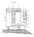
- two earth drilling units are provided, the essential parts of which are a drive motor 2, a transmission shaft 3 and a motor 3 driven by the shaft 3 Drill pipe 4 are.
- two identical earth drilling units 1 are provided, but there is also the possibility of being satisfied with a single unit of this type.
- the two twin units 1 shown in FIGS. 1 and 2 are arranged in a manner to be described in a part of a railway carriage 5, which can be moved on rails 7 by means of wheels 6, displaceable at right angles to the track axis.
- the remaining parts of the railway carriage 5 can be designed in any way. It would be possible to provide a lounge for the operating team, a material room and a compartment for the drill cores.
- each of the units concerned is attached to a carriage 8 which runs in corresponding guides 9 of a swivel plate 10.
- the motor 2 is firmly connected to the carriage 8, while the drill pipe 4 is slidably mounted within the block 11, which is also fastened to the swivel plate 10.
- the slide 8 At the top of the slide 8 there is the actuating plate 12, on which the cylinder-piston units 13 engage, by means of which the slide 8 together with the earth drilling unit 1 can be moved along the swivel plate 10 (in the starting position shown at right angles to the track level).
- the grid plate 14 is firmly connected to the swivel plate 10, which together with the swivel plate 10 and the drilling unit 1 can be swiveled about the geometric axis 15, so that bores can also be made below the sleepers or rails or finally laterally of the rail bed.
- the grid plate 16 works together with the grid plate 14, which in turn is firmly connected to the frame part 17, which together with the further frame part 18 and the crossbeam 19 forms the frame 20.
- One of the two grid plates has one resiliently projecting parts, which can enter corresponding recesses in the other grid plate. Furthermore, operating parts, not shown, are provided on the swivel plate 10, with which the swivel plate together with the drilling unit can be swiveled about axis 15 in accordance with the grid division of the two locking disks 14 and 16.
- a cylinder-piston unit 21 is arranged between the two frame parts 17 and 18 and a fixed part of the railroad car. Furthermore, each frame part 17 and 18 has a laterally projecting pin 22, which pins enter corresponding tabs 23 of one column 24 (the other is designated by 25) of a main frame 26, so that the pivot plate 10 by means of the two cylinder-piston unit 21 can be pivoted about the geometric axis of the bearing pin 22.
- the main frame 26 is suspended from the sliding frame 27, which essentially consists of two longitudinal bars 28 (only one is visible in the drawing) and two transverse bars 29. Both longitudinal bars 28 each run in a U-rail 3 equipped with roller rollers 30 and arranged transversely to the track axis, so that the sliding frame 27 and all attached to it guide. such as the two twin earth drilling units 1, can be moved back and forth at right angles to the track axis.
- the described displacement option allows the sliding frame 27 to be moved such that an earth drilling unit 1 is located approximately in the middle between the two rails 7, while the others come to lie outside the railroad car profile and thus also outside the track, so that bores can be made simultaneously between the two rails 7 and outside the track.
- the drill cores can then either be examined in the laboratory itself in the laboratory or they can be transported to a suitable location. As already mentioned, these drill cores then serve to obtain soil mechanics knowledge.
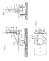
- FIGS. 3-7 schematically show a further embodiment of the subject matter of the invention, reference being made in particular with regard to the means for moving (rotating and pivoting) the earth drilling unit 1 to the design option shown in FIGS. 1 and 2.
- a base plate 32 is provided at one end of a railway carriage 5 and is fixedly connected to a toothed wheel 33.
- This gear 33 can be put into circulation by means of a pinion 34 meshing with it, the pinion in question being provided with any operating means.
- the base plate 32 At its edge facing the end of the carriage, the base plate 32 has two tabs through which the pivot axis 36 passes, as also through those (39) of the pivot plate 37.
- the position of the swivel axis 36 is selected such that when the swivel plate 37 which is rotatable about this axis is set up at right angles to the track plane, the earth drilling unit 1, which is displaceably mounted on this swivel plate 37, projects beyond the end of the carriage.
- the swivel plate 37 is connected to the frame 39 via two locking disks, the last of which can be swiveled about the axis 36 by means of the cylinder-piston unit 38.
- one (40) is fixedly connected to the pivot plate 37 and the other (41) to the frame 39, in accordance with the constructive solution in the first exemplary embodiment.
- the one not shown resilient, protruding locking means which are intended and suitable to engage in corresponding recesses in the other locking plate.
- the swivel plate 37 has on its outer side a guide for a carriage 42, on which the earth drilling unit 1 is fastened.
- This slide which, thanks to the guides mentioned, is arranged to be displaceable parallel to the axis of the swivel plate 37 on this last one, has an actuating extension 43, on which a cylinder-piston unit, not shown, acts laterally, by means of which the earth drilling unit 1 along the guide of the in Fig. 3 position perpendicular to the track level can be brought into a removal position parallel to this level.
- the first embodiment differs from that shown in FIGS. 3-7 in that the twin earth drilling unit according to the first embodiment is replaced by a single earth drilling unit, and that instead of the displaceability of the twin earth drilling units provided in the first embodiment, a single such unit at the end of a railroad car is arranged on a rotatable plate 32.
- the facility in question is concerned with taking drill samples at certain points in the area of a railway track, which can then be subjected to a laboratory test.
- care is taken to ensure that the drill cores can be removed from the drill pipe in the simplest possible manner.
- the drill pipe has a window 45 which extends over the length of a normal drill core and extends over half the circumference and which is rotated upward and opened when the drill pipe is pivoted, so that the drill core can be easily removed.
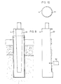
- 8 shows an exemplary embodiment of such a drill pipe.
- 46 denotes the driver driven by the motor, which enters corresponding T-shaped grooves 47 in the drill pipe 4.
- This configuration of the driver 46 and the upper part of the drill pipe not only permits rotary movements, but also the transmission of an axial force, such as must be expended when pulling the drill pipe out of the borehole.
- window 8 also shows the size of the window, the arrangement of which in the direction of the geometric axis of the drill pipe 4 corresponds to the length of a conventional drill core, and which extends over half the circumference of the drill pipe.
- window 45 is covered by plate 48, which is partially omitted in FIG. 8 for ease of understanding.
- the side window edge and the panel edge cooperating with it have corresponding projections, while along the lower edge the panel edge engages under the window edge with a projecting rib 49.
- the upper edge of the plate is connected to a reinforcing ring 50 by means of countersunk screws, which cannot be seen in the drawing, so that the plate 48 forms a closure of the window 45 during the drilling process, without additional resistance being counteracted by a radially projecting part of a rotary movement.
- FIGS. 9 and 10 Another possibility for the formation of the drill pipe 4 is shown in FIGS. 9 and 10 and consists in that the casing of the drill pipe 4 is slotted. A rough assessment of the various zones can consequently be carried out through the slot 51, this slot 51 additionally allowing laterally smaller drill pipes 52 to be inserted in order to be able to take soil samples from the drill core at certain points.
Landscapes
- Engineering & Computer Science (AREA)
- Life Sciences & Earth Sciences (AREA)
- Civil Engineering (AREA)
- Structural Engineering (AREA)
- General Life Sciences & Earth Sciences (AREA)
- Chemical & Material Sciences (AREA)
- Analytical Chemistry (AREA)
- Soil Sciences (AREA)
- Architecture (AREA)
- Mining & Mineral Resources (AREA)
- Paleontology (AREA)
- General Engineering & Computer Science (AREA)
- Sampling And Sample Adjustment (AREA)
- Earth Drilling (AREA)
- Analysing Materials By The Use Of Radiation (AREA)
- Investigating Strength Of Materials By Application Of Mechanical Stress (AREA)
Claims (3)
Priority Applications (1)
| Application Number | Priority Date | Filing Date | Title |
|---|---|---|---|
| AT83200715T ATE24561T1 (de) | 1982-05-26 | 1983-05-20 | Einrichtung zur gewinnung von bodenproben im bereiche von bahngleisen zum zwecke der ermittlung von bodenmechanischen kennwerten. |
Applications Claiming Priority (2)
| Application Number | Priority Date | Filing Date | Title |
|---|---|---|---|
| CH3240/82 | 1982-05-26 | ||
| CH324082 | 1982-05-26 |
Publications (3)
| Publication Number | Publication Date |
|---|---|
| EP0096431A2 EP0096431A2 (fr) | 1983-12-21 |
| EP0096431A3 EP0096431A3 (en) | 1984-12-19 |
| EP0096431B1 true EP0096431B1 (fr) | 1986-12-30 |
Family
ID=4251678
Family Applications (1)
| Application Number | Title | Priority Date | Filing Date |
|---|---|---|---|
| EP83200715A Expired EP0096431B1 (fr) | 1982-05-26 | 1983-05-20 | Dispositif pour l'obtention d'echantillons de sol aux abords de voies de chemin de fer dans le but d'explorer des caractéristiques mécaniques du sol |
Country Status (3)
| Country | Link |
|---|---|
| EP (1) | EP0096431B1 (fr) |
| AT (1) | ATE24561T1 (fr) |
| DE (1) | DE3368707D1 (fr) |
Cited By (1)
| Publication number | Priority date | Publication date | Assignee | Title |
|---|---|---|---|---|
| US11199478B2 (en) | 2019-09-25 | 2021-12-14 | Bnsf Railway Company | Systems and methods for confining ballast samples |
Families Citing this family (2)
| Publication number | Priority date | Publication date | Assignee | Title |
|---|---|---|---|---|
| FR2641753A1 (fr) * | 1989-01-18 | 1990-07-20 | Sefi | Vehicule ferroviaire de terrassement |
| SE9604318L (sv) * | 1996-11-25 | 1997-12-01 | Folke Soederberg | Kraftöverföringsanordning till borr för upptagning av markprover |
Family Cites Families (5)
| Publication number | Priority date | Publication date | Assignee | Title |
|---|---|---|---|---|
| FR906796A (fr) * | 1944-08-17 | 1946-01-18 | Appareil mobile pour le travail du sol et l'exécution des ouvrages y attenant, ainsi que pour la mesure de leur résistance | |
| FR1142380A (fr) * | 1954-06-01 | 1957-09-17 | Hands England Oilfields Equipm | Appareil de forage rotatif |
| FR2271343B1 (fr) * | 1974-01-29 | 1976-10-08 | Fondasol Tech | |
| US4316393A (en) * | 1980-06-04 | 1982-02-23 | Harry Philipenko | Soil sampler and mounting arrangement |
| DE3034704C2 (de) * | 1980-09-15 | 1982-10-28 | Hermann-Dieter Dr. 4300 Essen Koehne | Schienenfahrzeug für Gleiskörperarbeiten |
-
1983
- 1983-05-20 EP EP83200715A patent/EP0096431B1/fr not_active Expired
- 1983-05-20 AT AT83200715T patent/ATE24561T1/de not_active IP Right Cessation
- 1983-05-20 DE DE8383200715T patent/DE3368707D1/de not_active Expired
Cited By (1)
| Publication number | Priority date | Publication date | Assignee | Title |
|---|---|---|---|---|
| US11199478B2 (en) | 2019-09-25 | 2021-12-14 | Bnsf Railway Company | Systems and methods for confining ballast samples |
Also Published As
| Publication number | Publication date |
|---|---|
| ATE24561T1 (de) | 1987-01-15 |
| DE3368707D1 (en) | 1987-02-05 |
| EP0096431A2 (fr) | 1983-12-21 |
| EP0096431A3 (en) | 1984-12-19 |
Similar Documents
| Publication | Publication Date | Title |
|---|---|---|
| EP0992217B1 (fr) | Système de table d'opération | |
| DE4402464C1 (de) | Horizontalschiebefenster mit mindestens einem quer zur Rahmenebene bewegbaren Schiebeflügel | |
| DE68919206T2 (de) | Selbstfahrende vorrichtung zum betonieren von gräben. | |
| DE1271369B (de) | Vorrichtung zum Abstellen von Kraftfahrzeugen od. dgl. | |
| EP0391149B1 (fr) | Pont déplaçable et système pour la pose du pont | |
| DD152378A5 (de) | Verfahren und gleisfahrbare maschine zum entfernen von unregelmaessigkeiten an den schinenkopfoberflaeche verlegter gleise | |
| EP0139959A2 (fr) | Fraiseuse | |
| DE2733419A1 (de) | Vorrichtung zum verdichten und/oder glaetten von frischem beton o.dgl. | |
| DE102019001200A1 (de) | Erdbohrvorrichtung und Verwendung einer Erdbohrvorrichtung | |
| EP0690176B1 (fr) | File de modules séparateurs | |
| EP0008082B1 (fr) | Garage pour garer les véhicules l'un au-dessus de l'autre | |
| EP3045638A1 (fr) | Système de battant coulissant et rotatif | |
| CH654609A5 (de) | Fahrbare gleisbettungs-reinigungsmaschine. | |
| EP0096431A2 (fr) | Dispositif pour l'obtention d'echantillons de sol aux abords de voies de chemin de fer dans le but d'explorer des caractéristiques mécaniques du sol | |
| EP1197601B1 (fr) | Dispositif de fraisage-concassage | |
| DE3522918A1 (de) | Vorrichtung fuer den transport eines gleisabschnittes oder einer montierten gleisverbindung auf dem schienenwege | |
| DE3034704A1 (de) | Schienenfahrzeug fuer gleiskoerperarbeiten | |
| DE3835459C2 (fr) | ||
| DE3030473A1 (de) | Vorrichtung zum aus- und einbau (umbau) von weichen in eisenbahngleiskoerpern | |
| DE2523291C3 (de) | Zum öffnen eingerichteter Leitplankenabschnitt | |
| DE3725775A1 (de) | Strassenfraesmaschine mit auswechselbarer fraeswerkseinheit | |
| EP0755368B1 (fr) | Dispositif destine au retournage d'un compost | |
| EP0866170B1 (fr) | Dispositif de support pour la section des rails dans la zone de joint d'un bâtiment | |
| DE1248487B (de) | Kraftfahrzeug zum Transport von kastenfoermigen Baukoerpern, insbesondere Fertiggaragen | |
| DE19531952A1 (de) | Fugenschneideeinrichtung für Längs- und Querfugen |
Legal Events
| Date | Code | Title | Description |
|---|---|---|---|
| PUAI | Public reference made under article 153(3) epc to a published international application that has entered the european phase |
Free format text: ORIGINAL CODE: 0009012 |
|
| AK | Designated contracting states |
Designated state(s): AT BE CH DE FR GB IT LI LU NL SE |
|
| PUAL | Search report despatched |
Free format text: ORIGINAL CODE: 0009013 |
|
| AK | Designated contracting states |
Designated state(s): AT BE CH DE FR GB IT LI LU NL SE |
|
| 17P | Request for examination filed |
Effective date: 19850607 |
|
| GRAA | (expected) grant |
Free format text: ORIGINAL CODE: 0009210 |
|
| AK | Designated contracting states |
Kind code of ref document: B1 Designated state(s): AT BE CH DE FR GB IT LI LU NL SE |
|
| REF | Corresponds to: |
Ref document number: 24561 Country of ref document: AT Date of ref document: 19870115 Kind code of ref document: T |
|
| REF | Corresponds to: |
Ref document number: 3368707 Country of ref document: DE Date of ref document: 19870205 |
|
| ITF | It: translation for a ep patent filed | ||
| ET | Fr: translation filed | ||
| PLBE | No opposition filed within time limit |
Free format text: ORIGINAL CODE: 0009261 |
|
| STAA | Information on the status of an ep patent application or granted ep patent |
Free format text: STATUS: NO OPPOSITION FILED WITHIN TIME LIMIT |
|
| 26N | No opposition filed | ||
| PGFP | Annual fee paid to national office [announced via postgrant information from national office to epo] |
Ref country code: SE Payment date: 19890329 Year of fee payment: 7 |
|
| PGFP | Annual fee paid to national office [announced via postgrant information from national office to epo] |
Ref country code: GB Payment date: 19890430 Year of fee payment: 7 |
|
| PG25 | Lapsed in a contracting state [announced via postgrant information from national office to epo] |
Ref country code: GB Effective date: 19900520 |
|
| PG25 | Lapsed in a contracting state [announced via postgrant information from national office to epo] |
Ref country code: SE Effective date: 19900521 |
|
| GBPC | Gb: european patent ceased through non-payment of renewal fee | ||
| EPTA | Lu: last paid annual fee | ||
| EUG | Se: european patent has lapsed |
Ref document number: 83200715.7 Effective date: 19910115 |
|
| PGFP | Annual fee paid to national office [announced via postgrant information from national office to epo] |
Ref country code: LU Payment date: 19970702 Year of fee payment: 15 |
|
| PGFP | Annual fee paid to national office [announced via postgrant information from national office to epo] |
Ref country code: FR Payment date: 19980409 Year of fee payment: 16 |
|
| PGFP | Annual fee paid to national office [announced via postgrant information from national office to epo] |
Ref country code: NL Payment date: 19980430 Year of fee payment: 16 |
|
| PGFP | Annual fee paid to national office [announced via postgrant information from national office to epo] |
Ref country code: CH Payment date: 19980512 Year of fee payment: 16 Ref country code: BE Payment date: 19980512 Year of fee payment: 16 |
|
| PG25 | Lapsed in a contracting state [announced via postgrant information from national office to epo] |
Ref country code: LU Free format text: LAPSE BECAUSE OF NON-PAYMENT OF DUE FEES Effective date: 19980520 |
|
| PGFP | Annual fee paid to national office [announced via postgrant information from national office to epo] |
Ref country code: AT Payment date: 19990415 Year of fee payment: 17 |
|
| PG25 | Lapsed in a contracting state [announced via postgrant information from national office to epo] |
Ref country code: LI Free format text: LAPSE BECAUSE OF NON-PAYMENT OF DUE FEES Effective date: 19990531 Ref country code: CH Free format text: LAPSE BECAUSE OF NON-PAYMENT OF DUE FEES Effective date: 19990531 Ref country code: BE Free format text: LAPSE BECAUSE OF NON-PAYMENT OF DUE FEES Effective date: 19990531 |
|
| BERE | Be: lapsed |
Owner name: HCH HEINRICH GRONAU A.G. Effective date: 19990531 |
|
| PG25 | Lapsed in a contracting state [announced via postgrant information from national office to epo] |
Ref country code: NL Free format text: LAPSE BECAUSE OF NON-PAYMENT OF DUE FEES Effective date: 19991201 |
|
| REG | Reference to a national code |
Ref country code: CH Ref legal event code: PL |
|
| PG25 | Lapsed in a contracting state [announced via postgrant information from national office to epo] |
Ref country code: FR Free format text: LAPSE BECAUSE OF NON-PAYMENT OF DUE FEES Effective date: 20000131 |
|
| NLV4 | Nl: lapsed or anulled due to non-payment of the annual fee |
Effective date: 19991201 |
|
| REG | Reference to a national code |
Ref country code: FR Ref legal event code: ST |
|
| PG25 | Lapsed in a contracting state [announced via postgrant information from national office to epo] |
Ref country code: AT Free format text: LAPSE BECAUSE OF NON-PAYMENT OF DUE FEES Effective date: 20000520 |
|
| PGFP | Annual fee paid to national office [announced via postgrant information from national office to epo] |
Ref country code: DE Payment date: 20021119 Year of fee payment: 20 |