EP0096495A1 - Dispositif et procédé de mesure du flux cardiaque - Google Patents
Dispositif et procédé de mesure du flux cardiaque Download PDFInfo
- Publication number
- EP0096495A1 EP0096495A1 EP83302927A EP83302927A EP0096495A1 EP 0096495 A1 EP0096495 A1 EP 0096495A1 EP 83302927 A EP83302927 A EP 83302927A EP 83302927 A EP83302927 A EP 83302927A EP 0096495 A1 EP0096495 A1 EP 0096495A1
- Authority
- EP
- European Patent Office
- Prior art keywords
- chamber
- flow
- flow rate
- ventricle
- drive fluid
- Prior art date
- Legal status (The legal status is an assumption and is not a legal conclusion. Google has not performed a legal analysis and makes no representation as to the accuracy of the status listed.)
- Granted
Links
- 230000000747 cardiac effect Effects 0.000 title claims abstract description 35
- 238000005259 measurement Methods 0.000 title claims description 31
- 238000000034 method Methods 0.000 title description 38
- 239000008280 blood Substances 0.000 claims abstract description 49
- 210000004369 blood Anatomy 0.000 claims abstract description 49
- 239000012530 fluid Substances 0.000 claims abstract description 26
- 230000003247 decreasing effect Effects 0.000 claims 1
- 230000002861 ventricular Effects 0.000 abstract description 11
- 210000002216 heart Anatomy 0.000 description 55
- 239000007789 gas Substances 0.000 description 47
- 239000003570 air Substances 0.000 description 40
- 230000003205 diastolic effect Effects 0.000 description 8
- 208000028399 Critical Illness Diseases 0.000 description 6
- 239000012895 dilution Substances 0.000 description 6
- 238000010790 dilution Methods 0.000 description 6
- 210000003709 heart valve Anatomy 0.000 description 6
- 210000005241 right ventricle Anatomy 0.000 description 6
- 230000009471 action Effects 0.000 description 5
- 238000005086 pumping Methods 0.000 description 5
- 238000005070 sampling Methods 0.000 description 5
- 210000000709 aorta Anatomy 0.000 description 4
- FAPWRFPIFSIZLT-UHFFFAOYSA-M Sodium chloride Chemical compound [Na+].[Cl-] FAPWRFPIFSIZLT-UHFFFAOYSA-M 0.000 description 3
- QVGXLLKOCUKJST-UHFFFAOYSA-N atomic oxygen Chemical compound [O] QVGXLLKOCUKJST-UHFFFAOYSA-N 0.000 description 3
- 230000017531 blood circulation Effects 0.000 description 3
- 210000004204 blood vessel Anatomy 0.000 description 3
- 230000004087 circulation Effects 0.000 description 3
- 238000004590 computer program Methods 0.000 description 3
- 230000006870 function Effects 0.000 description 3
- 230000000004 hemodynamic effect Effects 0.000 description 3
- 230000010354 integration Effects 0.000 description 3
- 239000007788 liquid Substances 0.000 description 3
- 229910052760 oxygen Inorganic materials 0.000 description 3
- 239000001301 oxygen Substances 0.000 description 3
- 238000010992 reflux Methods 0.000 description 3
- CURLTUGMZLYLDI-UHFFFAOYSA-N Carbon dioxide Chemical compound O=C=O CURLTUGMZLYLDI-UHFFFAOYSA-N 0.000 description 2
- JOYRKODLDBILNP-UHFFFAOYSA-N Ethyl urethane Chemical compound CCOC(N)=O JOYRKODLDBILNP-UHFFFAOYSA-N 0.000 description 2
- 230000002411 adverse Effects 0.000 description 2
- 230000001746 atrial effect Effects 0.000 description 2
- 239000004020 conductor Substances 0.000 description 2
- 238000010276 construction Methods 0.000 description 2
- 230000002950 deficient Effects 0.000 description 2
- 238000003113 dilution method Methods 0.000 description 2
- 238000001727 in vivo Methods 0.000 description 2
- 229920000642 polymer Polymers 0.000 description 2
- 238000011084 recovery Methods 0.000 description 2
- 238000001356 surgical procedure Methods 0.000 description 2
- 238000011144 upstream manufacturing Methods 0.000 description 2
- 210000003462 vein Anatomy 0.000 description 2
- 241001465754 Metazoa Species 0.000 description 1
- XAGFODPZIPBFFR-UHFFFAOYSA-N aluminium Chemical compound [Al] XAGFODPZIPBFFR-UHFFFAOYSA-N 0.000 description 1
- 229910052782 aluminium Inorganic materials 0.000 description 1
- 239000012080 ambient air Substances 0.000 description 1
- 238000013459 approach Methods 0.000 description 1
- 238000010420 art technique Methods 0.000 description 1
- 238000009529 body temperature measurement Methods 0.000 description 1
- 229910002092 carbon dioxide Inorganic materials 0.000 description 1
- 239000001569 carbon dioxide Substances 0.000 description 1
- 210000005242 cardiac chamber Anatomy 0.000 description 1
- 210000001715 carotid artery Anatomy 0.000 description 1
- 230000008859 change Effects 0.000 description 1
- 230000008878 coupling Effects 0.000 description 1
- 238000010168 coupling process Methods 0.000 description 1
- 238000005859 coupling reaction Methods 0.000 description 1
- 238000001514 detection method Methods 0.000 description 1
- 238000011161 development Methods 0.000 description 1
- 230000000694 effects Effects 0.000 description 1
- 238000005516 engineering process Methods 0.000 description 1
- 229920002457 flexible plastic Polymers 0.000 description 1
- 238000003780 insertion Methods 0.000 description 1
- 230000037431 insertion Effects 0.000 description 1
- 238000011835 investigation Methods 0.000 description 1
- 210000005240 left ventricle Anatomy 0.000 description 1
- 210000004072 lung Anatomy 0.000 description 1
- 238000012423 maintenance Methods 0.000 description 1
- 230000007257 malfunction Effects 0.000 description 1
- 230000007246 mechanism Effects 0.000 description 1
- 238000012544 monitoring process Methods 0.000 description 1
- 230000036284 oxygen consumption Effects 0.000 description 1
- 238000012545 processing Methods 0.000 description 1
- 230000002035 prolonged effect Effects 0.000 description 1
- 210000001147 pulmonary artery Anatomy 0.000 description 1
- 238000011160 research Methods 0.000 description 1
- 238000012552 review Methods 0.000 description 1
- 230000035945 sensitivity Effects 0.000 description 1
- 230000011664 signaling Effects 0.000 description 1
- 230000009885 systemic effect Effects 0.000 description 1
- 238000012546 transfer Methods 0.000 description 1
- 230000007704 transition Effects 0.000 description 1
Images


Classifications
-
- G—PHYSICS
- G01—MEASURING; TESTING
- G01F—MEASURING VOLUME, VOLUME FLOW, MASS FLOW OR LIQUID LEVEL; METERING BY VOLUME
- G01F3/00—Measuring the volume flow of fluids or fluent solid material wherein the fluid passes through the meter in successive and more or less isolated quantities, the meter being driven by the flow
- G01F3/02—Measuring the volume flow of fluids or fluent solid material wherein the fluid passes through the meter in successive and more or less isolated quantities, the meter being driven by the flow with measuring chambers which expand or contract during measurement
- G01F3/20—Measuring the volume flow of fluids or fluent solid material wherein the fluid passes through the meter in successive and more or less isolated quantities, the meter being driven by the flow with measuring chambers which expand or contract during measurement having flexible movable walls, e.g. diaphragms, bellows
-
- A—HUMAN NECESSITIES
- A61—MEDICAL OR VETERINARY SCIENCE; HYGIENE
- A61B—DIAGNOSIS; SURGERY; IDENTIFICATION
- A61B5/00—Measuring for diagnostic purposes; Identification of persons
- A61B5/02—Detecting, measuring or recording for evaluating the cardiovascular system, e.g. pulse, heart rate, blood pressure or blood flow
- A61B5/026—Measuring blood flow
-
- A—HUMAN NECESSITIES
- A61—MEDICAL OR VETERINARY SCIENCE; HYGIENE
- A61M—DEVICES FOR INTRODUCING MEDIA INTO, OR ONTO, THE BODY; DEVICES FOR TRANSDUCING BODY MEDIA OR FOR TAKING MEDIA FROM THE BODY; DEVICES FOR PRODUCING OR ENDING SLEEP OR STUPOR
- A61M60/00—Blood pumps; Devices for mechanical circulatory actuation; Balloon pumps for circulatory assistance
- A61M60/10—Location thereof with respect to the patient's body
- A61M60/104—Extracorporeal pumps, i.e. the blood being pumped outside the patient's body
- A61M60/117—Extracorporeal pumps, i.e. the blood being pumped outside the patient's body for assisting the heart, e.g. transcutaneous or external ventricular assist devices
-
- A—HUMAN NECESSITIES
- A61—MEDICAL OR VETERINARY SCIENCE; HYGIENE
- A61M—DEVICES FOR INTRODUCING MEDIA INTO, OR ONTO, THE BODY; DEVICES FOR TRANSDUCING BODY MEDIA OR FOR TAKING MEDIA FROM THE BODY; DEVICES FOR PRODUCING OR ENDING SLEEP OR STUPOR
- A61M60/00—Blood pumps; Devices for mechanical circulatory actuation; Balloon pumps for circulatory assistance
- A61M60/10—Location thereof with respect to the patient's body
- A61M60/122—Implantable pumps or pumping devices, i.e. the blood being pumped inside the patient's body
- A61M60/165—Implantable pumps or pumping devices, i.e. the blood being pumped inside the patient's body implantable in, on, or around the heart
- A61M60/178—Implantable pumps or pumping devices, i.e. the blood being pumped inside the patient's body implantable in, on, or around the heart drawing blood from a ventricle and returning the blood to the arterial system via a cannula external to the ventricle, e.g. left or right ventricular assist devices
-
- A—HUMAN NECESSITIES
- A61—MEDICAL OR VETERINARY SCIENCE; HYGIENE
- A61M—DEVICES FOR INTRODUCING MEDIA INTO, OR ONTO, THE BODY; DEVICES FOR TRANSDUCING BODY MEDIA OR FOR TAKING MEDIA FROM THE BODY; DEVICES FOR PRODUCING OR ENDING SLEEP OR STUPOR
- A61M60/00—Blood pumps; Devices for mechanical circulatory actuation; Balloon pumps for circulatory assistance
- A61M60/10—Location thereof with respect to the patient's body
- A61M60/122—Implantable pumps or pumping devices, i.e. the blood being pumped inside the patient's body
- A61M60/196—Implantable pumps or pumping devices, i.e. the blood being pumped inside the patient's body replacing the entire heart, e.g. total artificial hearts [TAH]
-
- A—HUMAN NECESSITIES
- A61—MEDICAL OR VETERINARY SCIENCE; HYGIENE
- A61M—DEVICES FOR INTRODUCING MEDIA INTO, OR ONTO, THE BODY; DEVICES FOR TRANSDUCING BODY MEDIA OR FOR TAKING MEDIA FROM THE BODY; DEVICES FOR PRODUCING OR ENDING SLEEP OR STUPOR
- A61M60/00—Blood pumps; Devices for mechanical circulatory actuation; Balloon pumps for circulatory assistance
- A61M60/40—Details relating to driving
- A61M60/424—Details relating to driving for positive displacement blood pumps
- A61M60/427—Details relating to driving for positive displacement blood pumps the force acting on the blood contacting member being hydraulic or pneumatic
-
- A—HUMAN NECESSITIES
- A61—MEDICAL OR VETERINARY SCIENCE; HYGIENE
- A61M—DEVICES FOR INTRODUCING MEDIA INTO, OR ONTO, THE BODY; DEVICES FOR TRANSDUCING BODY MEDIA OR FOR TAKING MEDIA FROM THE BODY; DEVICES FOR PRODUCING OR ENDING SLEEP OR STUPOR
- A61M60/00—Blood pumps; Devices for mechanical circulatory actuation; Balloon pumps for circulatory assistance
- A61M60/50—Details relating to control
- A61M60/508—Electronic control means, e.g. for feedback regulation
-
- A—HUMAN NECESSITIES
- A61—MEDICAL OR VETERINARY SCIENCE; HYGIENE
- A61M—DEVICES FOR INTRODUCING MEDIA INTO, OR ONTO, THE BODY; DEVICES FOR TRANSDUCING BODY MEDIA OR FOR TAKING MEDIA FROM THE BODY; DEVICES FOR PRODUCING OR ENDING SLEEP OR STUPOR
- A61M60/00—Blood pumps; Devices for mechanical circulatory actuation; Balloon pumps for circulatory assistance
- A61M60/80—Constructional details other than related to driving
- A61M60/855—Constructional details other than related to driving of implantable pumps or pumping devices
- A61M60/89—Valves
- A61M60/892—Active valves, i.e. actuated by an external force
-
- A—HUMAN NECESSITIES
- A61—MEDICAL OR VETERINARY SCIENCE; HYGIENE
- A61M—DEVICES FOR INTRODUCING MEDIA INTO, OR ONTO, THE BODY; DEVICES FOR TRANSDUCING BODY MEDIA OR FOR TAKING MEDIA FROM THE BODY; DEVICES FOR PRODUCING OR ENDING SLEEP OR STUPOR
- A61M2205/00—General characteristics of the apparatus
- A61M2205/33—Controlling, regulating or measuring
- A61M2205/3331—Pressure; Flow
- A61M2205/3334—Measuring or controlling the flow rate
-
- A—HUMAN NECESSITIES
- A61—MEDICAL OR VETERINARY SCIENCE; HYGIENE
- A61M—DEVICES FOR INTRODUCING MEDIA INTO, OR ONTO, THE BODY; DEVICES FOR TRANSDUCING BODY MEDIA OR FOR TAKING MEDIA FROM THE BODY; DEVICES FOR PRODUCING OR ENDING SLEEP OR STUPOR
- A61M60/00—Blood pumps; Devices for mechanical circulatory actuation; Balloon pumps for circulatory assistance
- A61M60/10—Location thereof with respect to the patient's body
- A61M60/122—Implantable pumps or pumping devices, i.e. the blood being pumped inside the patient's body
- A61M60/126—Implantable pumps or pumping devices, i.e. the blood being pumped inside the patient's body implantable via, into, inside, in line, branching on, or around a blood vessel
- A61M60/148—Implantable pumps or pumping devices, i.e. the blood being pumped inside the patient's body implantable via, into, inside, in line, branching on, or around a blood vessel in line with a blood vessel using resection or like techniques, e.g. permanent endovascular heart assist devices
-
- A—HUMAN NECESSITIES
- A61—MEDICAL OR VETERINARY SCIENCE; HYGIENE
- A61M—DEVICES FOR INTRODUCING MEDIA INTO, OR ONTO, THE BODY; DEVICES FOR TRANSDUCING BODY MEDIA OR FOR TAKING MEDIA FROM THE BODY; DEVICES FOR PRODUCING OR ENDING SLEEP OR STUPOR
- A61M60/00—Blood pumps; Devices for mechanical circulatory actuation; Balloon pumps for circulatory assistance
- A61M60/80—Constructional details other than related to driving
- A61M60/855—Constructional details other than related to driving of implantable pumps or pumping devices
- A61M60/89—Valves
- A61M60/894—Passive valves, i.e. valves actuated by the blood
Definitions
- the present invention relates to systems and methods for providing cardiac flow measurement and, more particularly, to a system and method for providing measurement of the volume of blood pumped by an artificial heart.
- blood In the human circulatory system, blood is first pumped through the lungs, where oxygen and carbon dioxide are exchanged. It then returns to the heart and is pumped out into the systemic circulatory vessels.
- the blood leaves the heart through the aorta, which is typically 25 millimeters in diameter, and then flows on through progressively narrowing vessels until it reaches the capillaries, which are some eight micrometers in diameter.
- the blood then flows through progressively larger vessels as it moves, through the venous system, until it reaches the vena cava, where the vessel diameter is about 20 millimeters.
- the velocities that are encountered in the human circulatory system vary between 1 m/sec in the larger vessels to 10 -4 m/sec in the capillaries. Pressures may vary between 150 mm of Hg in the aorta to nearly zero in the major veins.
- the prime mover in the human circulatory system is the heart.
- the heart In a normal adult at rest, the heart has an output of about 5,000 ml/minute at a mean rate of about 70 beats per minute. During periods of exercise, this output can rise by a factor of five. Assuming a classical lifespan of about 70 years, before the end of its useful life a normal heart will have pumped approximately 200,000 tons of blood through the circulatory system, normally without maintenance.
- One of the more promising types of artificial hearts which has been developed consists of an artificial ventricle having a base on which is mounted a semi-rigid urethane polymer chamber which contains prosthetic heart valves to regulate the entry and exit of blood.
- the blood chamber and base are separated by a flexible diaphragm.
- the pumping action of the artificial ventricle is controlled by a "heart driver.”
- the function of the heart driver is to impart a pumping action to the flexible diaphragm. This may be done mechanically, hydraulically or pneumatically.
- the heart driver is connected to the base of the ventricle by a flexible plastic tube known as the "driver tube.”
- the driver tube is in turn connected at its origin to the outlet to an electropneumatic valve.
- the heart driver controls the valve so as to alternately connect the driver tubing to a source of compressed air during systole (i.e., during the phase of the heart's operation where blood is expelled from the heart) and to an exhaust port during diastole (i.e., that phase of the heart's operation where the heart is relaxed and the blood re-enters the heart chambers).
- systole compressed air is allowed to enter the gas chamber of the ventricle and in so doing exerts a force on the blood contained in the blood chamber of the ventricle via the flexible diaphragm. This force is sufficient to cause the flexible diaphragm to expel the blood through the outflow valve.
- the duration of the systolic phase of operation is electronically controlled and ends by de-actuation of the electropneumatic valve which then transfers the driver tubing connection from the compressed air source to the exhaust port. This releases the pressure on the flexible diaphragm so that blood can then re-fill the ventricle via the inflow valve.
- one widely known method for measuring cardiac output is called the Fick technique, which is performed by measuring the oxygen consumed by the patient by means of a specialized apparatus.
- Catheters are employed to withdraw venous blood at the right ventricle and arterial blood from the carotid artery.
- the difference in oxygen content between arterial and venous blood for any given oxygen consumption is an index of cardiac output, which may be calculated from these measured variables.
- the Fick method is rather laborious, has an undesirable aspect of requiring insertion of arterial and venous catheters as well as collection of expired gas, and has a measurement accuracy that is only in the range of ⁇ 10 - 20% of the actual cardiac output.
- Another prior art method for providing flow measurement is called the dye-dilution method. This method involves injecting dye into the blood stream at a point upstream of the ventricle and then sampling the blood downstream of the ventricle. The concentration of dye measured per unit of time in the blood downstream of the ventricle provides an indication of the cardiac output.
- the dye-dilution method also suffers from a relatively poor measurement accuracy, in the range of ⁇ 10 - 20% of the true value.
- the dye-dilution technique creates an additional problem by virtue of the fact that an artificial heart valve will not fully close when a catheter is threaded through the valve, which is necessary to inject the dye. Therefore, the artificial valve leaks considerably and it is not possible to provide a true and accurate measurement of cardiac flow under these circumstances.
- thermal-dilution technique which is described in an article entitled “Cardiac Output Measurement By Thermal-Dilution” by Sorenson et al. See Annals of Surgery, Vol. 183, No. 1, January 1976, pp. 67-72.
- This technique involves placing a catheter via a vein so that its tip passes through the right ventricle to lie in the pulmonary artery.
- a thermistor is located near the catheter tip.
- Cool saline solution is delivered into the upper end of the catheter, to emerge in the right ventricle and temperature measurements from the thermistor, at the downstream location, are measured over a given time interval and can be used to provide an estimate of cardiac output.
- thermal-dilution technique One problem with the thermal-dilution technique is the fact that changes in temperature of the saline solution occurring between its introduction point and measurement point render accurate detection and other measurement difficult.
- the technique has an accuracy of only f201 of the actual flow value.
- the thermal-dilution technique suffers from the same problem as the dye-dilution technique when used with an artificial heart, in that an artificial heart valve will not fully close when a catheter is threaded through it to introduce the saline solution into the patient's circulatory system.
- This device works particularly well on a laboratory bench, but experiences serious difficulties when employed in vivo.
- the electrodes must be firmly applied to the vessel wall; however, any movement of the body can adversely affect this arrangement.
- the wires connected to the electrodes and coil are fragile, and major surgery is required to put the device into the patient's body. Moreover, once the device is in the patient's body, it cannot be calibrated.
- the prior art systems for providing cardiac flow measurement do not provide the necessary degree of accuracy to be able to provide reliable data which can be used in diagnosing whether an artificial heart is properly functioning or which can be reliably used as the basis for controlling the heart driver.
- these prior art techniques have the further serious drawback that they involve invasive techniques which pose additional risk and discomfort to the patient, which is undesirable, particularly in the case of a critically ill cardiac patient.
- pressurized gas is applied during systole through a driver tube to the gas chamber of a ventricle of a pneumatically driven artificial heart and is exhausted therefrom during diastole.
- the gas chamber is separated from the ventricle blood chamber by a flexible diaphragm which mechanically transmits pressure but not flow between the gas and blood chambers.
- a flexible diaphragm which mechanically transmits pressure but not flow between the gas and blood chambers.
- the volume of blood entering the blood chamber during diastole is matched by an equivalent volume of gas exhausted from the gas chamber.
- the pressure in the gas exhaust path is essentially constant and quite close to ambient during this phase. Therefore, the volume of blood entering the ventricle during diastole can be measured as a function of the volume of air exhausted during diastole, which can easily be derived by measuring the rate of air. flow and then integrating.
- the volume of blood expelled from the ventricle during systole can be measured as a function of the volume of pressurized air applied to the gas chamber of the ventricle if a flow meter is used that measures rate of air flow independently of the air pressure.
- the volume of air applied to the gas chamber of the ventricle during systole is measured by measuring the rate of air flow through the driver tube independently of pressure and then integrating this flow rate with respect to time to derive the volume.
- a pneumotachograph is inserted in the driver tube to provide a differential pressure which is proportional to the flow rate but which is insensitive to absolute pressure changes occurring therein.
- the differential pressure is converted to a proportional analog voltage which is digitized by sampling the analog signal.
- the digitized data is then input to a digital computer where it is stored.
- the computer then performs the required integration.
- the output is then displayed both graphically and numerically on a terminal system.
- the method and apparatus of the present invention is relatively compact and simple to use, yet it provides measurement accuracies of within ⁇ 5-10% of actual ventricular output. Moreover, the technique is non-invasive, and thus does not cause additional risk, pain or discomfort to the patient, and yet aids the patient's treatment and recovery.
- the display of the air flow time curve contains information concerning the functional characteristics of the valves and ventricle.
- This information can provide early warning of ventricular malfunction or dangerous hemodynamic states, enabling corrective action to be taken before the patient is seriously endangered.
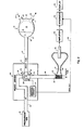
- an artificial ventricle is generally illustrated at 10.
- the artificial ventricle may be either a left or a right ventricle or ventricular assist device that is either implanted in the patient or that is located extracorporeally.
- the ventricle 10 is separated into two chambers 11 and 13 by a flexible diaphragm 15.
- a pumping action may be imparted to the flexible diaphragm 15 by means of a drive fluid that alternately enters into and then leaves chamber 11, or by means of a direct mechanical coupling to a piston or other similar mechanical device.
- the drive fluid may be gaseous (ie., a pneumatic system) or liquid (i.e., a a hydraulic system).
- the term "fluid” is intended to mean either a gaseous or a liquid drive fluid.
- ventricle 10 may be part of any pneumatically driven artificial heart or ventricular assist device and, for example, may be part of the Jarvik 7 Implantable Total Artificial Heart sold by Kolff Medical, of Salt Lake City, Utah.
- the two chambers 11 and 13 are separated by a flexible diaphragm 15 which is impervious to flow of gas or blood, but which transmits pressure differences between the chambers by flexing and thereby differentially varying the chamber volumes.
- the diaphragm is caused to flex by a pressurized gas so that it moves to a position such as illustrated by the dashed line configuration 15a.
- the diaphragm exerts a force on the blood in chamber 13, expelling it through an outflow value 14, as schematically represented by arrow 16.
- the pressurized gas is released or removed from chamber 11.
- Blood then re-enters chamber 13 through inflow valve 18, as schematically represented by arrow 22, and displaces the diaphragm to a position such as that illustrated at 15b.
- the ventricle 10 is typically made of an aluminum base 12 on which is mounted a semi-rigid urethane polymer shell 24 which contains the prosthetic heart valves 14, 18 which regulate the ingress and egress of blood.
- the pressurized gas chamber 11 is connected to a driver tube 17 which conducts pressurized gas into and out from the gas chamber 11. It should be noted that separate tubes and separate openings may be provided, if desired, for inlet and outlet of the gas.
- the base 12 is fitted with a tubular connector for connection to driver tube 17 at the ingress/egress port 19 of ventricle 10.
- driver tube 17 is connected through a port 21 of a heart driver unit 20 to an electropneumatically controlled valve 29.
- the heart driver 20 which is illustrated schematically in Figure 1, is electrically controlled by circuit 27 so that it alternately connects the valve 29 to a systole (or supply) port 23 and a diastole (or exhaust) port 25.
- valve 29 is connected so that it will conduct the pressurized gas from container 49 through a supply tube 31, elbow-shaped passageway 32 of valve 29, and to driver tube 17.
- valve 29 If the valve 29 is rotated 90° clockwise, as schematically represented by arrow 28, the elbow-shaped passageway 32 will complete the flow path between the driver tube 17 and exhaust tube 33, thus permitting the gas to be exhausted to atmosphere during diastole.
- the pressurized gas can be admitted to gas chamber 11 and then exhausted therefrom so as to cause the pumping action of diaphragm 15.
- valve 29 may be any suitable three-port solenoid valve or combination of solenoid valves.
- An example of a commercially available unit which can serve as the heart driver 20, including valve 29 and control circuit 27, is the Utah Heart Driver sold by Kolff Medical, of Salt Lake City, Utah, which is described and illustrated in detail in the Utah Heart Driver -- Operations, Specifications, and Parts Manual, dated February, 1981.
- the cardiac frequency, as controlled by this heart driver, is operator-adjustable by means of circuit 27.
- Figure 1 specifically illustrates one presently preferred embodiment which includes a single pass pneumatically driven ventricle
- the system could be hydraulic or pneumatic, and the drive fluid (either liquid or gas) could be recycled (i.e., a "multi-pass" system) rather than exhausted from the system with each cycle as in the case of a single pass system.
- the drive system could also be mechanical, in which case a piston or other similar device would be used to drive the diaphragm 15 rather than a fluid.
- the fluid admitted and expelled from chamber 11 during each cycle is passive--that is, does no work in terms of pumping diaphragm 15, and is used to simply fill the available space in chamber 11.
- Mechanical, hydraulic or pneumatic drive systems such as those described herein are well-known and are commercially available.
- a flow meter 37 is placed in the flow path of driver tube 17 at a point that is outside of the patient's body.
- flow meter 37 takes the form of a pneumotachograph, such as the Fleisch pneumotachograph Model i/a 7318 sold by OEM Medical, Inc., of Richmond, Virginia.
- any flow meter which is insensitive to the rapidly changing pressures developed by the air flow through driver tube 17 during systole or diastole could be used in place of the pneumotachograph.
- the pneumotachograph 37 provides a resistance by means of a resistive device 35 which comprises a large number of ducts (0.8 mm in diameter by 32 mm in length).
- the resistance 35 creates a differential pressure signal between two spaced points in the driver tube 17.
- This differential pressure appears across the pneumotachograph output passages 39 and 41 and, in accordance with Poiseuille's Law, is proportional to the rate of air flow through the tube 17.
- the differential pressure is applied to a pressure transducer 40 which, for example, may be a differential pressure transducer manufactured by Validyne Corp. of Northridge, California and sold as Model MP-45-14-871.
- Pressure transducer 40 converts the differential pressure to an analog voltage signal having an amplitude proportional to the applied differential pressure.
- the analog voltage is input to an amplifier 38 and is then digitized by an analog-to-digital (A/D) interface circuit 45.
- Amplifier 38 and A/D interface 45 are well known circuit elements that are state-of-the art integrated circuits.
- the A/D interface circuit 45 under the control of a microcomputer 44, which may be, for example, an Apple II Plus, samples the output signal from transducer 40 during systole or diastole.
- the transducer output is typically sampled and digitized to 12-bit accuracy every 1.025 milliseconds.
- the trigger signal for synchronizing the A/D interface circuit 45 to the onset of either systole or diastole is provided by a SYNC OUT signal from the control circuit 27 of the heart driver 20, as schematically represented by line 46.
- This signal provides appropriate pulses signaling the onset and termination of the systolic and diastolic phases, depending on whether the rate of air flow is to be measured during systole or diastole.
- 1200 samples are taken during each measurement cycle and stored as an array in the memory of microcomputer 44. Sampling terminates when a pulse, indicating the onset of the next phase, appears on the SYNC OUT line 46.
- the microcomputer 44 is programmed in accordance with well known digital programming techniques to search the array of stored digital values to find the beginning and end of the sampled phase. The computer then consecutively sums the stored values lying between these beginning and end points to obtain a result corresponding to the integral of the rate of air flow during the measured systolic or diastolic phase.
- a calibration equation is employed to convert the integrated air flow to stroke volume expressed in milliliters. This stroke volume can then be multiplied by the ventricular rate to yield a ventricular blood flow figure in terms of volume of blood pumped per unit of time.
- An example of one computer program which can be used in the system of the present invention is described in the computer listing of the appendix attached to this specification and incorporated herein by reference.
- the computer listing in the appendix comprises two separate parts. The first part is in Basic language and the second part is in 6502 microprocessor assembly language.
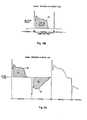
- the stroke volume and cardiac output values are displayed at the display terminal 43 of microcomputer 44. During this processing, sampling of the systolic or diastolic rate of air flow is suspended; sampling is resumed after the stroke volume and cardiac output values, which are computed from the previous samples, are displayed. Systolic or diastolic periods are sampled over approximately 30 seconds and the average results are graphically and numerically displayed as the average stroke volume and average cardiac output. A typical graph of the output (i.e. air flow versus time) is schematically illustrated in Figure 4a. If the cardiac output is derived from integration of the air flow/time curve 85 during diastole, the area represented by the cross-hatched area A is used.
- the cardiac output is derived from integrating the air flow time/curve 87 during systole
- the cross-hatched area B is used. In either case the cross-hatched area under the curve corresponds to within *5-102 of the volume of blood pumped by the ventricle 10.
- the form of the air flow/time curve 85, 87 recorded during diastole and systole contains important information of great diagnostic value concerning the operation of the inflow and outflow valves, and also concerning the hemodynamic state of the patient. Additionally, significant points on the air flow/time curve 85, 87 may be recognized by appropriate programming of the computer, which may be part of a sophisticated control system for the heart driver. For example, complete filling of the ventricle could result in zero air flow before the end of a pre-set diastolic length of time. Recognition of this complete filling could be used in a control system to terminate diastole and initiate the transition to systole.
- FIG. 2 An alternative embodiment of the system and method of the present invention is schematically illustrated in Figure 2. This embodiment differs only in that the flow meter 37 is placed in the flow path of the exhaust tube 33 rather than the driver tube 17, and the output of amplifier 38 is processed by an analog integrator 42 rather than by a digital computer. As more fully explained below, in this particular embodiment the cardiac flow measurements are derived solely from the rate of air flow exhausted during diastole.
- driver tube 17 and the gas chamber 11 contain air at end-systolic pressure, which pressure is usually on the order of 150 mm Hg above atmospheric pressure in the case of a left ventricle, and 70 mm Hg, in the case of the right ventricle.
- This gas rapidly escapes via driver tube 17 and exhaust port 25 and, as a consequence, the air pressure in the gas chamber 11 rapidly falls toward atmospheric pressure.
- the gas pressure in chamber 11 falls below the aortic pressure, there is a reflux of blood from the aorta into the ventricle blood chamber 13. This causes the outflow valve 14 to close.
- the inflow valve 18 opens and blood begins to enter the ventricle.
- the volume of blood entering blood chamber 13 during diastole displaces a corresponding volume of gas from gas chamber 11, which gas is vented to atmosphere via the valve 29 and exhaust tube 33.
- the pressure of the gas in the exhaust tube 33 during diastole is essentially constant and close to atmospheric pressure.
- the measurement of the volume of blood entering the blood chamber 13 during diastole may be derived from measurements of the volume of gas exhausted over the same period of time. This measurement corresponds to the time integral of the flow rate of the exhausted gas.
- the volume of gas exhausted during diastole is obtained by using the flow meter 37 to obtain the rate of air flow through exhaust tube 33. This rate is converted by transducer 40 to a corresponding electric signal 89 (see Figure 4b), which is then integrated over time.
- the integration can be done by means of a digital computer, as described in Figure 1, or by means of a conventional analog integrator 42 as shown in Figure 2.
- the pneumotachograph 37 and transducer 40 in conjunction with the integrator 42 and display 43, technically measure the cardiac "input” rather than the cardiac "output” because the volume measured is the volume which enters the ventricle during diastole. It should be noted that the cardiac input and output are not necessarily equal to each other during each diastolic phase because of backflow which occurs through the prosthetic heart valves 14, 18.
- the system is calibrated against the reading of a turbine flow meter in an artificial circulation path.
- the turbine flow meter responds only to forward flow and, therefore, measures true cardiac output.
- the calibration equation for the cardiac output measurement system is derived by plotting turbo-flow meter output against the number representing the integral of the diastolic air flow, in the manner explained above.
- the artificial circulation is permitted to run over a greater range of cardiac outputs than would be experienced in vivo.
- the equation of the line of best fit to the experimental points is obtained and the relevant constants are substituted into the computer program to provide a direct indication of volume, as illustrated in the computer listing provided in the appendix to this specification.
- the second method of calibration exploits the potential of the pneumotachograph system for estimating prosthetic heart valve backflow under real operating conditions.
- the pneumotachograph is calibrated directly with known flow rates of ambient air and the constants relating volume flow rate to the A/D output are substituted into the computer program. Synchronization can be effected by the SYNC CUT signal on line 46 to assure that only exhaust flow, and not supply flow, is measured.
- a source 49 of gas under pressure delivers pressurized gas through tube 51 to a heart driver unit 50.
- the heart driver may typically be the Utah Heart Driver referred to hereinabove, employed to serve two artificial ventricles 61, 63. Both ventricles 61, 63 are the same in their structure and operation as the ventricle 10 described earlier. Together, the two ventricles, one for the left side and one for the right side, constitute a total artificial heart.
- Two electropneumatically controlled valves 53, 55 are operated under control of the electronic circuit 57 to alternately vary the flow connections of two driver tubes 65, 67 between inlet tube 51 during systole and exhaust tubes 52, 58 during diastole. Specifically, valve 53 alternately connects driver tube 65 to inlet tube 51 or to exhaust tube 52, whereas valve 55 alternately connects driver tube 67 to inlet tube 51 or to exhaust tube 58.
- the driver tube 65 connects to the gas chamber 62 of ventricle 61, and the driver tube 67 connects to the gas chamber 64 of ventricle 63.
- heart driver 50 operates in the same manner described in relation to the embodiment of Figure 1 to periodically operate valves 53, 55 to effect systolic and diastolic phases of the ventricles 61, 63.
- air flow through exhaust tube 52 is shown as being measured by a conventional turbine-type flow meter 70.
- a Doppler ultrasonic flow meter could be used.
- the turbine-type flow meter 70 is disposed in the flow path such that passing gas causes a propeller (not shown) to rotate at an angular speed which is proportional to the exhaust gas flow rate.
- a built-in tachometer (not shown) converts the angular speed of the propeller to a proportional voltage appearing across terminals 71, 72.
- Flow meter 70 could also be situated upstream of valve 53 rather than in the exhaust tube 52. From terminals 71, 72, the signal representing the rate of air flow may be processed and integrated either digitally as in Figure 1, or by an analog integrator as in Figure 2.
- a hot wire anemometer 80 is employed in the exhaust passage and takes the form of a wire, film or thermistor, which is held at a given temperature by a constant current source 81. As gas flows past the anemometer element 80, the element cools such that its electrical resistance is changed. Since the current through the element is held constant, the voltage across the element changes in proportion to the change in resistance. This voltage, as measured across terminals 82, 83, is a measure of the rate of air flow, which may be integrated as described above to yield measurements of volume.
Landscapes
- Health & Medical Sciences (AREA)
- Heart & Thoracic Surgery (AREA)
- Engineering & Computer Science (AREA)
- Cardiology (AREA)
- Life Sciences & Earth Sciences (AREA)
- Veterinary Medicine (AREA)
- Biomedical Technology (AREA)
- Hematology (AREA)
- Animal Behavior & Ethology (AREA)
- General Health & Medical Sciences (AREA)
- Public Health (AREA)
- Anesthesiology (AREA)
- Mechanical Engineering (AREA)
- Physics & Mathematics (AREA)
- Physiology (AREA)
- Biophysics (AREA)
- Pathology (AREA)
- Medical Informatics (AREA)
- Molecular Biology (AREA)
- Surgery (AREA)
- Fluid Mechanics (AREA)
- General Physics & Mathematics (AREA)
- External Artificial Organs (AREA)
- Measuring Pulse, Heart Rate, Blood Pressure Or Blood Flow (AREA)
Applications Claiming Priority (2)
| Application Number | Priority Date | Filing Date | Title |
|---|---|---|---|
| US381965 | 1982-05-25 | ||
| US06/381,965 US4465063A (en) | 1982-05-25 | 1982-05-25 | Cardiac flow measurement system and method |
Publications (2)
| Publication Number | Publication Date |
|---|---|
| EP0096495A1 true EP0096495A1 (fr) | 1983-12-21 |
| EP0096495B1 EP0096495B1 (fr) | 1986-09-17 |
Family
ID=23507027
Family Applications (1)
| Application Number | Title | Priority Date | Filing Date |
|---|---|---|---|
| EP83302927A Expired EP0096495B1 (fr) | 1982-05-25 | 1983-05-23 | Dispositif et procédé de mesure du flux cardiaque |
Country Status (4)
| Country | Link |
|---|---|
| US (1) | US4465063A (fr) |
| EP (1) | EP0096495B1 (fr) |
| JP (1) | JPS5977861A (fr) |
| DE (1) | DE3366228D1 (fr) |
Cited By (4)
| Publication number | Priority date | Publication date | Assignee | Title |
|---|---|---|---|---|
| FR2736689A1 (fr) * | 1995-07-11 | 1997-01-17 | Sames Sa | Procedes de mesure de debit ou de commande d'une pompe, pompe et installation de projection de produit de revetement comprenant une telle pompe |
| EP2044965A3 (fr) * | 2000-10-12 | 2009-04-29 | Renal Solutions, Inc. | Appareil pour le contrôle de débit de fluide corporel dans des traitements de fluide extracorporel |
| US7998101B2 (en) | 2003-07-28 | 2011-08-16 | Renal Solutions, Inc. | Devices and methods for body fluid flow control in extracorporeal fluid treatment |
| EP1952833A4 (fr) * | 2005-10-03 | 2013-06-05 | Jms Co Ltd | Réservoir de stockage de sang de type fermé et système de circulation sanguine extracorporel utilisant ledit réservoir |
Families Citing this family (32)
| Publication number | Priority date | Publication date | Assignee | Title |
|---|---|---|---|---|
| DE3316101C1 (de) * | 1983-05-03 | 1984-08-23 | Forschungsgesellschaft für Biomedizinische Technik, 5100 Aachen | Redundante Kolbenpumpe zum Betrieb ein- oder mehrkammriger pneumatischer Blutpumpen |
| US4781715A (en) * | 1986-04-30 | 1988-11-01 | Temple University Of The Commonwealth System Of Higher Education | Cardiac prosthesis having integral blood pressure sensor |
| US4782817A (en) * | 1987-05-29 | 1988-11-08 | Abiomed Cardiovascular, Inc. | Ventricular support system |
| US4902272A (en) * | 1987-06-17 | 1990-02-20 | Abiomed Cardiovascular, Inc. | Intra-arterial cardiac support system |
| US4906229A (en) * | 1988-05-03 | 1990-03-06 | Nimbus Medical, Inc. | High-frequency transvalvular axisymmetric blood pump |
| US5045051A (en) * | 1989-03-14 | 1991-09-03 | Abiomed, Inc. | Leak detector |
| US5289823A (en) * | 1992-05-12 | 1994-03-01 | Colin Electronics Co., Ltd. | Non-invasive aortic blood flow sensor and method for non-invasively measuring aortic blood flow |
| DE19500154C1 (de) * | 1995-01-04 | 1996-10-17 | Fritz Giebler Gmbh | Infusionsschlauch für ein Infusionsgerät mit einem Blasendetektor |
| CA2472621A1 (fr) * | 2002-01-07 | 2003-07-17 | Micromed Technology, Inc. | Procede et systeme de regulation physiologique d'une pompe a sang implantable |
| US7074176B2 (en) * | 2003-05-15 | 2006-07-11 | Innovamedica S.A. De C.V. | Air-pressure powered driver for pneumatic ventricular assist devices |
| US20140322688A1 (en) * | 2006-03-03 | 2014-10-30 | EBM Corporation | System for evaluating cardiac surgery training |
| US9881523B2 (en) | 2009-11-04 | 2018-01-30 | University Of Scranton | Mechanical model of the cardiovascular system and method of demonstrating the physiology of the cardiovascular system |
| US9576504B2 (en) * | 2009-11-04 | 2017-02-21 | University Of Scranton | Mechanical model of the cardiovascular system and method of demonstrating the physiology of the cardiovascular system |
| JP5779324B2 (ja) * | 2010-07-06 | 2015-09-16 | Ckd株式会社 | 薬液供給システム |
| US9636443B2 (en) * | 2014-05-30 | 2017-05-02 | Bravo Biomed, Inc. | System for producing continuous mechanical energy to treat heart failure without the use of external energy source |
| CN104316627A (zh) * | 2014-11-06 | 2015-01-28 | 上海仪电分析仪器有限公司 | 气相色谱仪气体流量自动显示装置 |
| EP3135327A1 (fr) | 2015-08-31 | 2017-03-01 | Berlin Heart GmbH | Pompe destinee au transport de liquides et procede de determination d'un debit |
| JP5989881B2 (ja) * | 2015-09-28 | 2016-09-07 | Ckd株式会社 | 薬液供給システム |
| EP3634528B1 (fr) | 2017-06-07 | 2023-06-07 | Shifamed Holdings, LLC | Dispositifs de déplacement de fluide intravasculaire, systèmes et procédés d'utilisation |
| US11511103B2 (en) | 2017-11-13 | 2022-11-29 | Shifamed Holdings, Llc | Intravascular fluid movement devices, systems, and methods of use |
| EP3746149B1 (fr) | 2018-02-01 | 2025-08-06 | Shifamed Holdings, LLC | Pompes à sang intravasculaires |
| WO2020028537A1 (fr) | 2018-07-31 | 2020-02-06 | Shifamed Holdings, Llc | Pompes sanguines intravasculaires et procédés d'utilisation |
| WO2020073047A1 (fr) | 2018-10-05 | 2020-04-09 | Shifamed Holdings, Llc | Pompes à sang intravasculaires et procédés d'utilisation |
| WO2021011473A1 (fr) | 2019-07-12 | 2021-01-21 | Shifamed Holdings, Llc | Pompes à sang intravasculaires et méthode d'utilisation et procédé de fabrication |
| US11654275B2 (en) | 2019-07-22 | 2023-05-23 | Shifamed Holdings, Llc | Intravascular blood pumps with struts and methods of use and manufacture |
| US12465748B2 (en) | 2019-08-07 | 2025-11-11 | Supira Medical, Inc. | Catheter blood pumps and collapsible pump housings |
| US11724089B2 (en) | 2019-09-25 | 2023-08-15 | Shifamed Holdings, Llc | Intravascular blood pump systems and methods of use and control thereof |
| WO2021062260A1 (fr) | 2019-09-25 | 2021-04-01 | Shifamed Holdings, Llc | Pompes à sang de cathéter et conduits sanguins pliables |
| EP4501393A3 (fr) | 2019-09-25 | 2025-04-09 | Shifamed Holdings, LLC | Pompes à sang à cathéter et boîtiers de pompes pliables |
| EP4072650A4 (fr) | 2019-12-11 | 2024-01-10 | Shifamed Holdings, LLC | Pompes à sang d'aorte descendante et de veine cave |
| EP4077947A4 (fr) | 2019-12-19 | 2024-01-10 | Shifamed Holdings, LLC | Pompes à sang intravasculaires, moteurs et commande de fluide |
| CN117664538A (zh) * | 2022-09-07 | 2024-03-08 | 浙江智柔科技有限公司 | 一种用于心室减容装置的测试设备及其测试方法 |
Citations (3)
| Publication number | Priority date | Publication date | Assignee | Title |
|---|---|---|---|---|
| US3718044A (en) * | 1971-12-07 | 1973-02-27 | Us Army | Flow meter for indirectly measuring the flow of blood from a blood pump |
| DE2658104A1 (de) * | 1976-05-19 | 1977-12-01 | Herwig Dipl Ing Dr Thoma | Vorrichtung zum automatischen betrieb kuenstlicher kreislaufpumpen |
| GB2004942A (en) * | 1977-09-21 | 1979-04-11 | Bosio R | Pump for producing an artificial blood circulation |
Family Cites Families (2)
| Publication number | Priority date | Publication date | Assignee | Title |
|---|---|---|---|---|
| US3376660A (en) * | 1965-07-12 | 1968-04-09 | Westinghouse Electric Corp | Circulatory system simulator |
| SU733688A1 (ru) * | 1977-11-23 | 1980-05-15 | Институт Трансплантации Органов И Тканей | Устройство косвенного контрол производительности протеза сердца с внешним пневмоприводом |
-
1982
- 1982-05-25 US US06/381,965 patent/US4465063A/en not_active Expired - Lifetime
-
1983
- 1983-05-23 DE DE8383302927T patent/DE3366228D1/de not_active Expired
- 1983-05-23 EP EP83302927A patent/EP0096495B1/fr not_active Expired
- 1983-05-25 JP JP58090871A patent/JPS5977861A/ja active Pending
Patent Citations (3)
| Publication number | Priority date | Publication date | Assignee | Title |
|---|---|---|---|---|
| US3718044A (en) * | 1971-12-07 | 1973-02-27 | Us Army | Flow meter for indirectly measuring the flow of blood from a blood pump |
| DE2658104A1 (de) * | 1976-05-19 | 1977-12-01 | Herwig Dipl Ing Dr Thoma | Vorrichtung zum automatischen betrieb kuenstlicher kreislaufpumpen |
| GB2004942A (en) * | 1977-09-21 | 1979-04-11 | Bosio R | Pump for producing an artificial blood circulation |
Non-Patent Citations (1)
| Title |
|---|
| SOVIET INVENTIONS ILLUSTRATED, Sections P,Q, week D02, It. Feb., 1981 DERWENT PUBLICATIONS LTD.: London, (P-34); & SU-A-733688 * |
Cited By (5)
| Publication number | Priority date | Publication date | Assignee | Title |
|---|---|---|---|---|
| FR2736689A1 (fr) * | 1995-07-11 | 1997-01-17 | Sames Sa | Procedes de mesure de debit ou de commande d'une pompe, pompe et installation de projection de produit de revetement comprenant une telle pompe |
| EP2044965A3 (fr) * | 2000-10-12 | 2009-04-29 | Renal Solutions, Inc. | Appareil pour le contrôle de débit de fluide corporel dans des traitements de fluide extracorporel |
| US7998101B2 (en) | 2003-07-28 | 2011-08-16 | Renal Solutions, Inc. | Devices and methods for body fluid flow control in extracorporeal fluid treatment |
| EP1952833A4 (fr) * | 2005-10-03 | 2013-06-05 | Jms Co Ltd | Réservoir de stockage de sang de type fermé et système de circulation sanguine extracorporel utilisant ledit réservoir |
| EP2708250A1 (fr) * | 2005-10-03 | 2014-03-19 | JMS Co., Ltd. | Réservoir de sang de type fermé et appareil de circulation sanguine extracorporelle ayant des moyens de d'élimination des bulles. |
Also Published As
| Publication number | Publication date |
|---|---|
| DE3366228D1 (en) | 1986-10-23 |
| US4465063A (en) | 1984-08-14 |
| EP0096495B1 (fr) | 1986-09-17 |
| JPS5977861A (ja) | 1984-05-04 |
Similar Documents
| Publication | Publication Date | Title |
|---|---|---|
| EP0096495B1 (fr) | Dispositif et procédé de mesure du flux cardiaque | |
| US5509424A (en) | Continuous cardiac output monitoring system | |
| EP3809960B1 (fr) | Systèmes d'identification de système | |
| US11666746B2 (en) | Medical product comprising a functional element for the invasive use in a patient's body | |
| US5788647A (en) | Method, system and apparatus for evaluating hemodynamic parameters | |
| US6186956B1 (en) | Method and system for continuously monitoring cardiac output | |
| US6746431B2 (en) | Combined catheter system for IABP and determination of thermodilution cardiac output | |
| US4901734A (en) | Dual-thermistor thermodilution catheter | |
| US4781715A (en) | Cardiac prosthesis having integral blood pressure sensor | |
| Schima et al. | Noninvasive monitoring of rotary blood pumps: necessity, possibilities, and limitations | |
| US20100130874A1 (en) | Apparatus and method for determining a physiologic parameter | |
| JP5337821B2 (ja) | 動的な心肺相互作用パラメータの非侵襲測定のための方法及びその装置 | |
| JP2020531122A (ja) | 血液ポンプ | |
| US5009234A (en) | For the thermodilution method of determining cardiac output | |
| JP2888609B2 (ja) | 血液補助循環装置 | |
| US20100094144A1 (en) | Systems and methods for determining cardiac output using pulmonary artery pressure measurements | |
| JP2002177226A (ja) | 脈遷移時間を決定するための処理及び装置及びそのような装置を有する体外血液療法設備 | |
| WO1999033502A1 (fr) | Appareil auxiliaire de circulation sanguine utilisant une pompe a flux sanguin continu et dispositif de diagnostic des conditions de la circulation sanguine dans l'organisme | |
| US6004275A (en) | System for the measurement of continuous cardiac output | |
| Gawlikowski et al. | The methods of physical parameters measurement regarding the heart supporting automation | |
| US12629507B2 (en) | Medical product comprising a functional element for the invasive use in a patient's body | |
| Jebson et al. | Pulsatile flow simulator for comparison of cardiac output measurements by electromagnetic flow meter and thermodilution | |
| WO2000053087A1 (fr) | Procede et appareil pour calculer le debit cardiaque d'un patient | |
| WO2022108539A1 (fr) | Ensemble cathéter et système | |
| HK40051050A (en) | Systems for system identification |
Legal Events
| Date | Code | Title | Description |
|---|---|---|---|
| PUAI | Public reference made under article 153(3) epc to a published international application that has entered the european phase |
Free format text: ORIGINAL CODE: 0009012 |
|
| AK | Designated contracting states |
Designated state(s): DE FR GB |
|
| 17P | Request for examination filed |
Effective date: 19840327 |
|
| GRAA | (expected) grant |
Free format text: ORIGINAL CODE: 0009210 |
|
| AK | Designated contracting states |
Kind code of ref document: B1 Designated state(s): DE FR GB |
|
| REF | Corresponds to: |
Ref document number: 3366228 Country of ref document: DE Date of ref document: 19861023 |
|
| ET | Fr: translation filed | ||
| PLBE | No opposition filed within time limit |
Free format text: ORIGINAL CODE: 0009261 |
|
| STAA | Information on the status of an ep patent application or granted ep patent |
Free format text: STATUS: NO OPPOSITION FILED WITHIN TIME LIMIT |
|
| 26N | No opposition filed | ||
| PGFP | Annual fee paid to national office [announced via postgrant information from national office to epo] |
Ref country code: FR Payment date: 19900418 Year of fee payment: 8 |
|
| PGFP | Annual fee paid to national office [announced via postgrant information from national office to epo] |
Ref country code: DE Payment date: 19900420 Year of fee payment: 8 |
|
| PGFP | Annual fee paid to national office [announced via postgrant information from national office to epo] |
Ref country code: GB Payment date: 19900427 Year of fee payment: 8 |
|
| PG25 | Lapsed in a contracting state [announced via postgrant information from national office to epo] |
Ref country code: GB Effective date: 19910523 |
|
| GBPC | Gb: european patent ceased through non-payment of renewal fee | ||
| PG25 | Lapsed in a contracting state [announced via postgrant information from national office to epo] |
Ref country code: FR Effective date: 19920131 |
|
| PG25 | Lapsed in a contracting state [announced via postgrant information from national office to epo] |
Ref country code: DE Effective date: 19920303 |
|
| REG | Reference to a national code |
Ref country code: FR Ref legal event code: ST |