EP0096530B1 - Appareil de balayage - Google Patents
Appareil de balayage Download PDFInfo
- Publication number
- EP0096530B1 EP0096530B1 EP83303139A EP83303139A EP0096530B1 EP 0096530 B1 EP0096530 B1 EP 0096530B1 EP 83303139 A EP83303139 A EP 83303139A EP 83303139 A EP83303139 A EP 83303139A EP 0096530 B1 EP0096530 B1 EP 0096530B1
- Authority
- EP
- European Patent Office
- Prior art keywords
- transport
- air
- shaft
- drum
- housing
- Prior art date
- Legal status (The legal status is an assumption and is not a legal conclusion. Google has not performed a legal analysis and makes no representation as to the accuracy of the status listed.)
- Expired - Lifetime
Links
- 239000000463 material Substances 0.000 claims abstract description 30
- 230000003287 optical effect Effects 0.000 claims abstract description 6
- 238000006243 chemical reaction Methods 0.000 claims abstract description 4
- 230000004044 response Effects 0.000 claims description 2
- 230000032258 transport Effects 0.000 description 87
- 230000033001 locomotion Effects 0.000 description 11
- 229920005372 Plexiglas® Polymers 0.000 description 9
- 239000004926 polymethyl methacrylate Substances 0.000 description 9
- 239000004593 Epoxy Substances 0.000 description 8
- 230000007246 mechanism Effects 0.000 description 8
- 239000011521 glass Substances 0.000 description 6
- 239000004411 aluminium Substances 0.000 description 5
- 229910052782 aluminium Inorganic materials 0.000 description 5
- XAGFODPZIPBFFR-UHFFFAOYSA-N aluminium Chemical compound [Al] XAGFODPZIPBFFR-UHFFFAOYSA-N 0.000 description 5
- 230000001276 controlling effect Effects 0.000 description 3
- 239000002184 metal Substances 0.000 description 3
- 229910052751 metal Inorganic materials 0.000 description 3
- 229910000906 Bronze Inorganic materials 0.000 description 2
- XEEYBQQBJWHFJM-UHFFFAOYSA-N Iron Chemical compound [Fe] XEEYBQQBJWHFJM-UHFFFAOYSA-N 0.000 description 2
- 239000010974 bronze Substances 0.000 description 2
- KUNSUQLRTQLHQQ-UHFFFAOYSA-N copper tin Chemical compound [Cu].[Sn] KUNSUQLRTQLHQQ-UHFFFAOYSA-N 0.000 description 2
- 238000007789 sealing Methods 0.000 description 2
- CYTYCFOTNPOANT-UHFFFAOYSA-N Perchloroethylene Chemical compound ClC(Cl)=C(Cl)Cl CYTYCFOTNPOANT-UHFFFAOYSA-N 0.000 description 1
- 240000002878 Prunus cerasus Species 0.000 description 1
- 208000027418 Wounds and injury Diseases 0.000 description 1
- 230000009471 action Effects 0.000 description 1
- 230000004888 barrier function Effects 0.000 description 1
- 230000008878 coupling Effects 0.000 description 1
- 238000010168 coupling process Methods 0.000 description 1
- 238000005859 coupling reaction Methods 0.000 description 1
- 230000006378 damage Effects 0.000 description 1
- 230000005484 gravity Effects 0.000 description 1
- 208000014674 injury Diseases 0.000 description 1
- 230000037431 insertion Effects 0.000 description 1
- 238000003780 insertion Methods 0.000 description 1
- 229910052742 iron Inorganic materials 0.000 description 1
- QSHDDOUJBYECFT-UHFFFAOYSA-N mercury Chemical compound [Hg] QSHDDOUJBYECFT-UHFFFAOYSA-N 0.000 description 1
- 229910052753 mercury Inorganic materials 0.000 description 1
- 229920003223 poly(pyromellitimide-1,4-diphenyl ether) Polymers 0.000 description 1
- 239000004814 polyurethane Substances 0.000 description 1
- 229920002635 polyurethane Polymers 0.000 description 1
- 230000001105 regulatory effect Effects 0.000 description 1
- 230000000284 resting effect Effects 0.000 description 1
- 230000001360 synchronised effect Effects 0.000 description 1
Images








Classifications
-
- H—ELECTRICITY
- H04—ELECTRIC COMMUNICATION TECHNIQUE
- H04N—PICTORIAL COMMUNICATION, e.g. TELEVISION
- H04N1/00—Scanning, transmission or reproduction of documents or the like, e.g. facsimile transmission; Details thereof
- H04N1/04—Scanning arrangements, i.e. arrangements for the displacement of active reading or reproducing elements relative to the original or reproducing medium, or vice versa
- H04N1/06—Scanning arrangements, i.e. arrangements for the displacement of active reading or reproducing elements relative to the original or reproducing medium, or vice versa using cylindrical picture-bearing surfaces, i.e. scanning a main-scanning line substantially perpendicular to the axis and lying in a curved cylindrical surface
- H04N1/0607—Scanning a concave surface, e.g. with internal drum type scanners
- H04N1/0621—Scanning a concave surface, e.g. with internal drum type scanners using a picture-bearing surface stationary in the main-scanning direction
- H04N1/0635—Scanning a concave surface, e.g. with internal drum type scanners using a picture-bearing surface stationary in the main-scanning direction using oscillating or rotating mirrors
-
- H—ELECTRICITY
- H04—ELECTRIC COMMUNICATION TECHNIQUE
- H04N—PICTORIAL COMMUNICATION, e.g. TELEVISION
- H04N1/00—Scanning, transmission or reproduction of documents or the like, e.g. facsimile transmission; Details thereof
- H04N1/04—Scanning arrangements, i.e. arrangements for the displacement of active reading or reproducing elements relative to the original or reproducing medium, or vice versa
- H04N1/06—Scanning arrangements, i.e. arrangements for the displacement of active reading or reproducing elements relative to the original or reproducing medium, or vice versa using cylindrical picture-bearing surfaces, i.e. scanning a main-scanning line substantially perpendicular to the axis and lying in a curved cylindrical surface
- H04N1/0607—Scanning a concave surface, e.g. with internal drum type scanners
-
- H—ELECTRICITY
- H04—ELECTRIC COMMUNICATION TECHNIQUE
- H04N—PICTORIAL COMMUNICATION, e.g. TELEVISION
- H04N1/00—Scanning, transmission or reproduction of documents or the like, e.g. facsimile transmission; Details thereof
- H04N1/04—Scanning arrangements, i.e. arrangements for the displacement of active reading or reproducing elements relative to the original or reproducing medium, or vice versa
- H04N1/06—Scanning arrangements, i.e. arrangements for the displacement of active reading or reproducing elements relative to the original or reproducing medium, or vice versa using cylindrical picture-bearing surfaces, i.e. scanning a main-scanning line substantially perpendicular to the axis and lying in a curved cylindrical surface
- H04N1/0671—Scanning arrangements, i.e. arrangements for the displacement of active reading or reproducing elements relative to the original or reproducing medium, or vice versa using cylindrical picture-bearing surfaces, i.e. scanning a main-scanning line substantially perpendicular to the axis and lying in a curved cylindrical surface with sub-scanning by translational movement of the main-scanning components
-
- H—ELECTRICITY
- H04—ELECTRIC COMMUNICATION TECHNIQUE
- H04N—PICTORIAL COMMUNICATION, e.g. TELEVISION
- H04N1/00—Scanning, transmission or reproduction of documents or the like, e.g. facsimile transmission; Details thereof
- H04N1/04—Scanning arrangements, i.e. arrangements for the displacement of active reading or reproducing elements relative to the original or reproducing medium, or vice versa
- H04N1/06—Scanning arrangements, i.e. arrangements for the displacement of active reading or reproducing elements relative to the original or reproducing medium, or vice versa using cylindrical picture-bearing surfaces, i.e. scanning a main-scanning line substantially perpendicular to the axis and lying in a curved cylindrical surface
- H04N1/08—Mechanisms for mounting or holding the sheet around the drum
-
- H—ELECTRICITY
- H04—ELECTRIC COMMUNICATION TECHNIQUE
- H04N—PICTORIAL COMMUNICATION, e.g. TELEVISION
- H04N1/00—Scanning, transmission or reproduction of documents or the like, e.g. facsimile transmission; Details thereof
- H04N1/04—Scanning arrangements, i.e. arrangements for the displacement of active reading or reproducing elements relative to the original or reproducing medium, or vice versa
- H04N1/06—Scanning arrangements, i.e. arrangements for the displacement of active reading or reproducing elements relative to the original or reproducing medium, or vice versa using cylindrical picture-bearing surfaces, i.e. scanning a main-scanning line substantially perpendicular to the axis and lying in a curved cylindrical surface
- H04N1/08—Mechanisms for mounting or holding the sheet around the drum
- H04N1/083—Holding means
- H04N1/0873—Holding means for holding the sheet on the internal surface of the drum
Definitions
- This invention relates generally to scanning apparatus for example for scanning sheet material whether for reading it or writing on it by means of laser beam for example when writing the pages of a newspaper.
- the scanning apparatus includes a rotatable optical arrangement mounted on air journal bearings, and a linear motor for providing axial drive between stops. Inaccuracies can result from slight errors in longitudinal positioning of the optical components due to end thrusts on the rotating mechanism.
- the scanning system includes a pair of opposed air thrust bearings between the housing and the shaft, each bearing comprising a cavity, means for supplying air under pressure to the cavity, and an air flow restricting element, whereby the supply of air from the cavity to each thrust bearing gap can be independently controlled.
- end thrusts can be substantially balanced so that they do not give rise to the inaccuracies that were occasionally experienced in the prior proposal.
- each air flow restricting element comprises a porous plate and that in turn may constitute one of the relatively rotational surfaces of the thrust bearing.
- Rotation is conveniently by means of a reaction air jet turbine, preferably at each end of the rotating, mechanism, and the turbine body itself may define the rotating thrust bearing surface.
- Supply of air to the turbine or turbines can be along the interior of the shaft, and the pressure of the supply of air for that purpose can be controlled by a servo mechanism in accordance with the measured speed of rotation to tend to keep that speed constant.
- the invention is related to the inventions, the subject of Patent Application Nos 83303138.8 and 83303137.0 claiming respectively a bed and support arrangement for facilitating drive of a transport in the scanner, and receiving a transport from the scanner after it has been scanned, and an arrangement of a transport for receiving a sheet to be scanned and drive means for feeding the transport and sheet into a cylindrical surface for scanning.
- Opposed thrust bearings are of course known in the engineering field as disclosed for example in Swearingen's US patent US-A-3 895 689 in connection with a high speed turbine which has no axial movement of the shaft for operation.
- FIGURE 1 is an overall schematic of the scanning device for reading and/or writing using laser beams.
- a cylinder drum (243) having side walls (244) carries support member (131) which in turn supports cradle (130) which in turn supports the housing (101) which contains rotating elements (120) with mirrors for reflecting the laser beams onto the materials to be read and/or written upon.
- the mirrors provide scanning by rotational and translational movement.
- the rotary motion is achieved by virtue of turbines (118) ( Figure 2) which are operated by compressed airfed into the housing (101).
- Linear motion of the housing (101) and with it the elements (120) is provided by a lead screw (133), which is rotated by a stepping motor (136), (shown in Figure 3) and which passes through the internally threaded housing (138) attached to the support (131) by a clamp (139).
- the lead screw (133) is supported by bearings (134) located in casings (140) and (141) on a base (1400).
- the reading and/or writing material is placed on a transport (150) ( Figure 6) which is placed on bed (191) in front of bar (192), ( Figure 1). when it is desired to move the transport (150) ( Figure 6), carrying the materials to be read and/or to be written upon, into the drum (243), the bar (192) is moved forwardly a short distance which causes the transport plate (150) to pass to a group of pinch rollers (one of which (202) is shown in Figure 1). These rollers drive the transport (150) into drum (243) as will be more fully explained.
- a second transport (150) having areas for reading and writing material may be placed on two L-section brackets (195,197) mounted at either side of the apparatus to pivot on shaft (196, 198) on supports (235, 236) as shown in Figure 13.
- the second transport (150) may be dropped upon the bed (191) by rotating the bracket (195) and its corresponding bracket on the other side of the machine
- the second transport (150) therefore, drops by gravity on the bed (191) and has the material for scanning placed on it.
- air is exhausted from cylinders (200) to lower bed (191) so that the horizontal sections of brackets (195) are at the level to receive the returned first transport (150) that was previously fed into the machine.
- the material in the reading and writing sections of the first transport (150), may then be changed to provide a new page for the newspaper after the second transport (150) has been loaded and the first transport (150) dropped.
- the cylinders (200) must be placed under air pressure, or relieved of air pressure, as necessary to position the bed (191) and brackets (195,197) correctly ( Figure 13).
- Vacuum provided by a vacuum pump (248) is used to hold the transport (150) in place in the drum (243) during scanning.
- a ramp (249) is provided between the bed (191) and the drum (243) for guiding the transport when passing to and from the drum (243).
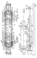
- a shaft (102) rotates in the housing (101) in air bearings (100) at each end of the housing (101) around the axis (109).
- Air under pressure from 5.5-6.9.10'Pa (5.6 to 7.0 Kgs per square cm) is connected to input (103) and enters an annular slot (105) which completely encircles the outer portion of each bearing (100).
- the air under pressure also enters annular trough (104) through holes (1030), to thus provide an air bearing surface between the rotating shaft (102) and the bearing (100).
- This air gap (106) between bearing (100) and shaft (102) is approximately 0.007 cms wide. Movement of air along the gap (106) is restricted by annular seals (107) leaving a gap of 0.0005 cms. They are of Vespel manufactured by Dupont.
- O rings (108) prevent leakage of the air from the inlet (103).
- a cap (110) connected to the housing (101) has a vent (111) communicating with radial holes (1110) ( Figure 20) whereby any air which leaks past seal (107) is vented to the atmosphere. Some air from the gap (106) also passes the seals (107) to space (113)..
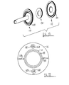
- Figure 20 illustrates certain details of one of the caps (110) and shows a pair of diametrically disposed axial-bores (1100) for bolts (1101) passing into the housing (101).
- Air under pressure controlled by a servo mechanism flows through inlet (114), the space (116), air ports (115), the interior of the shaft (102) and ports (117) to drive the air reaction turbines (118), one at each end of the shaft.
- the servo mechanism (142) ( Figure 5) is a Series T5100 current-to-pressure transducer manufactured by Fairchild Industrial Products Division, 1501, Fairchild Drive, Winston-Salem, North Carolina. Preferably this apparatus is catalogue number T5120-1 having an input impedance of 2,340 ohms and an input range of 1 to 5 milliamperes.
- the turbines are rotated at each end of the housing (101) and their end plates (119) in turn rotate optical housings (120), one at each end of the housing (101), which carry with them mirrors (121) and lenses (122), both of which, therefore, rotate at the same speed as the turbines (118).
- the air pressures in the cavities (123) are separately regulated by pressure regulators (1232) and (1233), ( Figure 2) which are adjusted experimentally to achieve maximum stability and maintain the housing centred between the turbines (118) by the air thrust bearings at the gaps (124, 125).
- Each end plate (119) on the turbine rotor is attached to the end of the shaft (102) by a ring (127) attached to the plate (119) and screwed into the threaded inner surface (126) of shaft (102).
- Tapped holes (128) in the ends of plates (119) carry set screws for balancing the rotating mechanism mechanically.
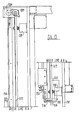
- Figure 19 is an exploded view of the details of one of the bronze porous plates (124).
- the end thrust can be substantially eliminated by adjustment of the pressure regulations controlling the air pressure in the gap between the thrust surfaces respectively at (125) on the turbine and at (124) on the porous plate.
- a pick-off (not shown) gives a signal response to the speed of rotation of the shaft (102) for supply to the servo mechanism (142) to control the pressure supplied at (114) to tend to keep the shaft speed constant.
- Figure 3 shows the supporting mechanism for the apparatus shown in Figure 2.
- the housing (101) is supported by the cradle (130) which is mounted on the slide support (131), which is manufactured by Pneumo Precision, Inc, Precision Park, Keene, New Hampshire.
- a stationary rail (132) supports the slide (131) by means of air pressure.
- a lead screw (133) Running parallel to, and alongside the rail (132) is a lead screw (133) which is supported by a journal bearing (134) at the right hand end and a journal and thrust bearing (134) at the left hand end which co-operates with a collar (135) on the lead screw to prevent unwanted lateral movement.
- the lead screw (133) is rotated by stepping motor (136) through a coupling (137).
- the stepping motor (136) may be model M8362 series motor/driver manufactured by Com- pumotor Corporation, 1310, Ross Street, Petaluma, California. This has 25,000 steps per revolution, and a preferred speed of approximately 1 revolution per second. Using a 10 pitch lead screw (133), the apparatus of Figure 2 scans approximately 400 lines per cm during reading or writing. Following the scanning of a complete page, the stepping motor runs in reverse at a speed of approximately 6 revolutions per second in order to return the apparatus of Figure 2 to its starting position for a new scan.
- the stepping motor is a synchronous motor so that the exact lateral position of the scanning system ( Figure 2) at any given time can be determined electrically.
- the preferred speed for the turbine (118) is 6,000 rpm whereby the mirrors rotate at that speed during scanning.
- Figure 4 shows from above the stepping motor (136) driving the lead screw (133) in a lead screw nut (138), which is held by bracket (139) firmly attached to the support slide (131) which is carried by the rail (132) on an air bearing.
- Figure 5 shows how in the device of Figure 2, a laser beam (145) enters axially from the left; it is focused by the lens (122) onto the mirror (121) ( Figure 2) and as the mirror rotates, the laser beam is reflected to provide scanning.
- This beam periodically passes encoder (143) which receives one signal pulse for each revolution of the mirror (121) to be used for counting and synchronizing.
- the encoder (143) is supported by bracket (144) from the cradle (130) and repeats that pulse back through the optical system.
- That beam is for the reading scan.
- Figure 6 shows a transport (150) for transporting the material which is to be read (usually one full page), or the laser plate upon which writing will occur in the direction of the arrow 154 into the drum of the machine.
- the transport (150) is basically a sheet of epoxy glass NEMA G-10, which is flexible so it can follow the inner curved surface of the drum (243) shown in Figure 1.
- the sheet (150) has metal strips (151) and (152) along its forward and rear ends.
- the forward strip (151) has indents (153) for the purpose of coarse registration. Precise registration is achieved by a metal strip (155) having a registration hole (156) near its right end and a registration slot (157) near its left end.
- Each pin (159) has a base (160) and a washer (161) to hold it in place.
- strips (162) of polyurethane tape define the areas for the reading and writing materials. Strips (162) serve basically as a vacuum barrier sealing in place the material on which reading or writing is to be undertaken.
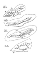
- a page of material which is to be converted into a printing plate is placed in the reading section, which is the left-hand rectangular section of Figure 6 bounded by tape (162), and a sheet of Plexiglas (163) ( Figure 8) having clearance holes (164) for the pins (159), is applied on top of the material.
- a strip of tape (165) ( Figures 8 and 12) acts as a hinge and enables the Plexiglas sheet (163) to be opened like a book for the insertion or removal of material to be read.
- a flap (166) ( Figure II) is securely bonded to the glass epoxy sheet (150); it is not bonded or sealed to the Plexiglas sheet (163) and constitutes a flap which may be used to cover the right edge of the Plexiglas sheet (163).
- the Plexiglas sheet (163) is transparent and non- polarised.
- the flap (166) has slits (167) to prevent buckling when the epoxy glass sheet (150) is curved. The flaps hold the materials against the transport (150) as it curves into the drum (243).
- Figure 9 is a detail of the right hand section which is used to hold the output material (such as a printing plate or lasermask) on which writing may take place.
- the strips of tape (162) serve the same function for the writing (right hand) rectangle as they did for the reading (left-hand) rectangle. They are covered by a flap (168) which is secured to the epoxy sheet (150) by tape (169). Slits (170) are provided to prevent buckling.
- a flexible thin aluminium plate is positioned on the epoxy sheet (150) beneath the output material and is held along its left edge by flap (168). Its right edge is held by flap (171) ( Figure 10).
- Flap (171) is hinged by a piece of tape (172) so that the flap may be raised out of the way so that the aluminium plate and the output material can be placed in position and their left and right hand edges covered by flaps (168) and (171), so that the transport sheet (150) and the elements held by that sheet, are ready for movement into position for reading and writing.
- Figure 11 shows the rear right hand corner of the Plexiglas sheet (163).
- Two strips of tape (174) are applied over the top of strip (162) so that the three strips of tape (162) and (174) equal the thickness of the Plexiglas sheet (163).
- the flap (166) is placed on top of tape (174) and is held in place by the strip of tape (175) which acts as a hinge for strip (166).
- a position-sensing magnet (176) is located on the leading strip (151).
- the ends (177), (178), (180) and (181) of the leading and rear strips (155) and (152) are thinner than the remainder for engagement by a pinch roller for driving the sheet (150) into position.
- Two identical transports (150) of the type shown in Figures 6 and 8 are normally used.
- the one which is first fed into the drum (243) will be called the first transport (150) and the other one will be called the second transport.
- Figures 13, 14, 15 and 16 show the table on which the transport (150) of Figure 6 is mounted before being fed into the machine for reading or writing.
- the bed (191) of the table is supported above the frame (190) of the equipment with the bar (192) at its rear edge.
- the bar has a normal (rear) position shown in full lines and a forward position shown in dotted lines.
- the rear end of metal strip (152) of the transport (150) ( Figure 6) is placed on the table directly in front of bar (192) when the latter is in its rear (full-line) position.
- the overall width of the transport (150) ( Figure 6) is slightly less than the distance between the vertical members (193) and (194) of the brackets (195) and (197).
- the upper ends of the vertical members (193) and (194) are pivoted at (196) and (198) respectively.
- the length of transport (150), including strips (151) and (152) is slightly less than the lengths of brackets (195) and (197).
- Four air cylinders (200) operate in synchronism to raise and lower the table.
- the table bed (191) When there is air pressure in the upper sections of the four cylinders (200), the table bed (191) is in its lower position and when air pressure is applied to the lower section of the four cylinders the bed (191) moves to an upper position about 2.5 cms above the lower position.
- a motor (205) drives timing pulley (206) carrying a belt (207) for turning the driving rollers (201) and (203).
- a second transport (150) is laid on the shelves (211) and (212) of brackets (195) and (197).
- air pressure is applied to cylinders (213) and (214) to cause arms (215) and (216), to rotate the brackets (195) and (197) outwardly about their pivots (196) and (198) so that the second transport (150) will fall from the brackets onto the bed (191) between guides (217) and (218).
- the brackets (195) and (197) are now ready to receive the first transport (150) after it has been scanned in the drum.
- the arms (220) and (221) pivot into contact with the epoxy glass on the first transport (150) and then they are moved rearwardly to drive the transport until the rear edge of strip (152) is above the forward edge of bar (192) in its rearward (solid line) lower position, (pressure has been removed from cylinder (210).
- the arms (220) and (221) are moved by Stilson Miniature Rota-clamps, each comprising a housing (226) and a shaft (227).
- the housing (226) is supported by a frame (230) which is part of the bracket (195).
- an air cylinder (224) When the forward end of shaft (227) is pressed rearwardly by an air cylinder (224), the arm (220) first rotates until it contacts the first transport (150), and then it translates rearwardly until it moves the first transport (150) to its ultimate final position above the edge of bar (192).
- the second clamp (228, 229, 231, 225) is similar.
- the drum (243) which is fed with a transport (150), is bounded by a wall (237) ( Figure 16) which has an opening (238), covered by a door (239), pivoted at (240), for preventing the laser beam from causing injury.
- a mercury switch operated by rotation of the shaft (240) de- energises a solenoid to move a shield (not shown) to a position which prevents the laser beam from being directed toward the opening (238).
- the door (239) is closed.
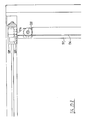
- Figure 17 illustrates the apparatus at the left end of the drum.
- the ramp (249) has an upstanding flange (250) at each side thereof, to guide the transport into the drum (243).
- sensor 257
- sensor 257
- shoulder screw 259
- the side walls of the left hand slot (153) in the forward strip (151) of the transport (150) straddle a pin 263 on a rotatable disc (251) so that when the shoulder screw (259) moves upwardly, it clamps the left end of strip (151) to the disc (251) ( Figure 17).
- the sensor (257) also energises a motor (2520) having a shaft (252) for rotating the disc (251) through gears (253) and (254) to move transport (150) along slot (264) to its final position.
- a pin (261) on the drum engages registration hole (157) (see Figure 6) and thereby ensures that the transport is registered with the inside surface of the drum (243).
- the pin (261) in the slot (157) is in alignment with hole (262) in the drum (243), whereupon air pressure is applied to cylinder (260) to press pin (261) through the hole (157) and into the hole (262) in order to hold the transport (150) and disc (251) in precise position in relation to the drum during scanning.
- the disc (251) is supported to rotate on rollers (256) about the drum (243) axis.
- a magnet (2510) on the disc (251) in co-operation with a sensor (2511) controls a circuit (2512) for de-energising the motor (2520) and thus, stopping motor shaft (252) in a position where pin (261) registers with hole (262).
- Circuit (2512) controls a valve (2513) to admit air to cylinder (260) to move pin (261) into hole (262).
- the disc (251), bearings (256), cylinders (258) and (260), shoulder screw (259) and registering pin (261), together with hole (262) are located along the left hand margin of the transport (150), within the drum, for the purpose of driving and registering the left hand portion of the transport (150). Similar devices are located at the right hand side of drum (243).
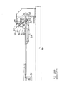
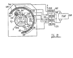
- Figure 18 is a sectional view of the drum showing the vacuum system and is a view from the right hand side, as distinguished from Figure 17, which is a view from the left hand side.
- the transport (150) has holes (265) ( Figure 6) extending completely through the epoxy glass sheet (150) and located just below the upper piece of tape (162) for sealing the output material.
- the aluminium plate which is used for making a printing plate extends from the lower piece of tape (162) ( Figure 6) to the lower edge of the holes (265) so that there is a space between the upper end of the aluminium plate and the lower end of the upper strip of tape (162) and the holes (265) communicate with that space and are in alignment with a groove (266) which runs across the drum (243) parallel to the axis.
- the groove (266) is connected by tubing to a solenoid valve (267) which is in turn connected to one of two separate inputs of vacuum pump (248).
- the output material (not shown) covers the air space between the upper edge of the aluminium plate and the lower edge of the forward strip of tape (162) and the vacuum created in groove (266) and extending through the holes (265) sucks the output material toward the epoxy glass plate (150) along a limited upper portion of the output material.
- the output material is held in position along its right and left hand sides, until vacuum is applied by the flaps (168) and (171) ( Figure 10).
- Solenoid valves (267) and (268) are controlled by an electrical circuit (2512) which causes these valves to open when the pin (261) is registered in the hole (262).
- Grooves (269) and 270) run across drum (243) and apply vacuum to the upper part of the transport (150) to hold it firmly against the inside wall of drum (243).
- the vacuum for grooves (269) and (270) comes from the second input of the pump (248).
- a cam (271) when it is normally at an angular position 180° from that shown, is not actuating either of two switches (272) and (273).
- a squeegee roller (274) is in its inward position (274a). Circuit (2512) starts motor (2710) for rotating the cam (271) clockwise. The squeegee roller (274) then moves outwardly into contact with the transport (150), under the force of air pressure fed into the cylinder (275). As the cam (271) rotates clockwise, the squeegee roller (274) similarly swings clockwise until it reaches the position (274b).
- each of grooves (277, 278, 280 and 281) runs across the drum (243) parallel to the axis, and when vacuum is applied the transport (150) is sucked against the inner wall of the drum (243).
- the cam (271) was rotating by about 160° the squeegee roller (274) has been held against the inner wall of the transport (150) and has applied pressure to press the transport (150) against the inner wall of the drum (243), to thus iron out any bubbles or other irregularities.
- the suction through grooves (266, 269, and 270) is applied as soon as the pin (261) registers with hole (262).
- the squeegee (274) is extended, and cam (271) and squeegee (274) begin rotating clockwise to first move the cam into position, and secondly start the squeegee pressing the transport against the inner wall of (243).
- the squeegee is so positioned with respect to the switches (272) and (273) that the squeegee passes over the portion of the transport (150) that is covered by vacuum grooves (270) and (278) before suction is applied to those grooves.
- the squeegee (274) passes over the portion of transport (150) that is covered by grooves (280) and (281) before the vacuum is applied to those grooves.
- the air pressure to cylinder (275) is reversed and the squeegee (274) retracts.
- the solenoid valves (267, 268, 276 and 279) are then de-energised, and pin (261) is retracted from hole (262) by cutting off the air pressure to cylinder (260).
- the transport (150) is now free to be removed from the drum (243).
- the motor (2520) which is controlling disc (251) is then reversed and the transport (150) is then ejected from the drum.
Landscapes
- Engineering & Computer Science (AREA)
- Multimedia (AREA)
- Signal Processing (AREA)
- Manufacture Or Reproduction Of Printing Formes (AREA)
- Magnetic Bearings And Hydrostatic Bearings (AREA)
- Facsimile Scanning Arrangements (AREA)
- Facsimiles In General (AREA)
- Mechanical Optical Scanning Systems (AREA)
- Analysing Materials By The Use Of Radiation (AREA)
- Vehicle Body Suspensions (AREA)
- Lubrication Of Internal Combustion Engines (AREA)
- Holo Graphy (AREA)
- Photoreceptors In Electrophotography (AREA)
Claims (9)
Priority Applications (1)
| Application Number | Priority Date | Filing Date | Title |
|---|---|---|---|
| AT83303139T ATE56335T1 (de) | 1982-06-02 | 1983-06-01 | Abtastapparat. |
Applications Claiming Priority (2)
| Application Number | Priority Date | Filing Date | Title |
|---|---|---|---|
| US06/383,930 US4501467A (en) | 1982-06-02 | 1982-06-02 | Scanning system employing a laser beam |
| US383930 | 1982-06-02 |
Publications (3)
| Publication Number | Publication Date |
|---|---|
| EP0096530A2 EP0096530A2 (fr) | 1983-12-21 |
| EP0096530A3 EP0096530A3 (en) | 1986-12-10 |
| EP0096530B1 true EP0096530B1 (fr) | 1990-09-05 |
Family
ID=23515347
Family Applications (1)
| Application Number | Title | Priority Date | Filing Date |
|---|---|---|---|
| EP83303139A Expired - Lifetime EP0096530B1 (fr) | 1982-06-02 | 1983-06-01 | Appareil de balayage |
Country Status (6)
| Country | Link |
|---|---|
| US (1) | US4501467A (fr) |
| EP (1) | EP0096530B1 (fr) |
| JP (1) | JPS5977766A (fr) |
| AT (1) | ATE56335T1 (fr) |
| CA (1) | CA1207824A (fr) |
| DE (1) | DE3381859D1 (fr) |
Families Citing this family (3)
| Publication number | Priority date | Publication date | Assignee | Title |
|---|---|---|---|---|
| US5422737A (en) * | 1991-06-05 | 1995-06-06 | Dainippon Screen Manufacturing Co. | Device for mounting an original onto an image reading drum |
| US5515182A (en) * | 1992-08-31 | 1996-05-07 | Howtek, Inc. | Rotary scanner |
| EP0989735A1 (fr) | 1998-09-22 | 2000-03-29 | Fujifilm Electronic Imaging Limited | Appareil de balayage d'image |
Family Cites Families (7)
| Publication number | Priority date | Publication date | Assignee | Title |
|---|---|---|---|---|
| US3030744A (en) * | 1960-03-08 | 1962-04-24 | Harig Mfg Corp | Air film bearing for machine tools |
| US3895689A (en) * | 1970-01-07 | 1975-07-22 | Judson S Swearingen | Thrust bearing lubricant measurement and balance |
| US3744858A (en) * | 1971-06-15 | 1973-07-10 | Apex Bearings Co | Gas bearings |
| US3938191A (en) * | 1974-08-21 | 1976-02-10 | The Singer Company | Rotary data base with air bearing |
| US4139243A (en) * | 1975-12-31 | 1979-02-13 | Logetronics, Inc. | Protective system for a pneumatically actuated rotating body |
| US4131916A (en) * | 1975-12-31 | 1978-12-26 | Logetronics, Inc. | Pneumatically actuated image scanning reader/writer |
| US4262594A (en) * | 1978-12-22 | 1981-04-21 | Logescan Systems, Inc. | Method and apparatus for manipulating and transporting image media |
-
1982
- 1982-06-02 US US06/383,930 patent/US4501467A/en not_active Expired - Fee Related
-
1983
- 1983-06-01 DE DE8383303139T patent/DE3381859D1/de not_active Expired - Fee Related
- 1983-06-01 AT AT83303139T patent/ATE56335T1/de not_active IP Right Cessation
- 1983-06-01 CA CA000429431A patent/CA1207824A/fr not_active Expired
- 1983-06-01 EP EP83303139A patent/EP0096530B1/fr not_active Expired - Lifetime
- 1983-06-02 JP JP58098759A patent/JPS5977766A/ja active Granted
Also Published As
| Publication number | Publication date |
|---|---|
| JPS5977766A (ja) | 1984-05-04 |
| ATE56335T1 (de) | 1990-09-15 |
| DE3381859D1 (de) | 1990-10-11 |
| EP0096530A2 (fr) | 1983-12-21 |
| EP0096530A3 (en) | 1986-12-10 |
| US4501467A (en) | 1985-02-26 |
| JPH0223114B2 (fr) | 1990-05-22 |
| CA1207824A (fr) | 1986-07-15 |
Similar Documents
| Publication | Publication Date | Title |
|---|---|---|
| EP0095936B1 (fr) | Appareil et procédé d'analyse | |
| JP2823481B2 (ja) | 電子部品自動装着装置 | |
| EP0096530B1 (fr) | Appareil de balayage | |
| CN118024752A (zh) | 一种热升华彩色打印和膜切一体机 | |
| JPH02109049A (ja) | カラースキャナ | |
| US5818508A (en) | Imaging device and media handling apparatus | |
| EP0095937B1 (fr) | Appareil et procédé d'analyse | |
| US4479148A (en) | Method and apparatus for insuring that the transport of a scanning system is contiguous with its support | |
| CN209455120U (zh) | 一种驾驶证自助制证设备 | |
| US4488716A (en) | Method of feeding material to and receiving it from a scanning system | |
| US4488717A (en) | Apparatus for feeding material to and receiving material from a scanning system | |
| JP2826026B2 (ja) | ドクタブレードの高さ位置調節方法及びその装置 | |
| US5560596A (en) | Sheet supplying device and recording or reading apparatus | |
| US6043865A (en) | Imagesetter | |
| GB2285016A (en) | Feeding paper to an interior drum type printer. | |
| US4511205A (en) | Scanning system wherein the scanning beam rotates and translates | |
| US6104475A (en) | Platesetter | |
| KR0158741B1 (ko) | 인쇄회로기판 이송장치 | |
| JPS6354055A (ja) | 画像読取り装置 | |
| CN222664780U (zh) | 一种带有自动校对功能的搬运机构 | |
| JP3150552B2 (ja) | 表面検査装置 | |
| US3300208A (en) | Card positioning apparatus and method | |
| WO2025200102A1 (fr) | Machine tout-en-un d'impression couleur par sublimation à colorant thermique et de coupe de film | |
| US20020018111A1 (en) | Method for controlling exposure and scan-exposure apparatus | |
| JPH08163328A (ja) | マイクロフィルムスキャナ |
Legal Events
| Date | Code | Title | Description |
|---|---|---|---|
| PUAI | Public reference made under article 153(3) epc to a published international application that has entered the european phase |
Free format text: ORIGINAL CODE: 0009012 |
|
| AK | Designated contracting states |
Designated state(s): AT BE CH DE FR GB IT LI LU NL SE |
|
| PUAL | Search report despatched |
Free format text: ORIGINAL CODE: 0009013 |
|
| AK | Designated contracting states |
Kind code of ref document: A3 Designated state(s): AT BE CH DE FR GB IT LI LU NL SE |
|
| 17P | Request for examination filed |
Effective date: 19861219 |
|
| 17Q | First examination report despatched |
Effective date: 19890405 |
|
| ITTA | It: last paid annual fee | ||
| GRAA | (expected) grant |
Free format text: ORIGINAL CODE: 0009210 |
|
| AK | Designated contracting states |
Kind code of ref document: B1 Designated state(s): AT BE CH DE FR GB IT LI LU NL SE |
|
| PG25 | Lapsed in a contracting state [announced via postgrant information from national office to epo] |
Ref country code: SE Effective date: 19900905 Ref country code: NL Effective date: 19900905 Ref country code: LI Effective date: 19900905 Ref country code: IT Free format text: LAPSE BECAUSE OF FAILURE TO SUBMIT A TRANSLATION OF THE DESCRIPTION OR TO PAY THE FEE WITHIN THE PRESCRIBED TIME-LIMIT;WARNING: LAPSES OF ITALIAN PATENTS WITH EFFECTIVE DATE BEFORE 2007 MAY HAVE OCCURRED AT ANY TIME BEFORE 2007. THE CORRECT EFFECTIVE DATE MAY BE DIFFERENT FROM THE ONE RECORDED. Effective date: 19900905 Ref country code: FR Effective date: 19900905 Ref country code: CH Effective date: 19900905 Ref country code: BE Effective date: 19900905 Ref country code: AT Effective date: 19900905 |
|
| REF | Corresponds to: |
Ref document number: 56335 Country of ref document: AT Date of ref document: 19900915 Kind code of ref document: T |
|
| REF | Corresponds to: |
Ref document number: 3381859 Country of ref document: DE Date of ref document: 19901011 |
|
| REG | Reference to a national code |
Ref country code: CH Ref legal event code: PL |
|
| EN | Fr: translation not filed | ||
| NLV1 | Nl: lapsed or annulled due to failure to fulfill the requirements of art. 29p and 29m of the patents act | ||
| PG25 | Lapsed in a contracting state [announced via postgrant information from national office to epo] |
Ref country code: LU Free format text: LAPSE BECAUSE OF NON-PAYMENT OF DUE FEES Effective date: 19910630 |
|
| PLBE | No opposition filed within time limit |
Free format text: ORIGINAL CODE: 0009261 |
|
| STAA | Information on the status of an ep patent application or granted ep patent |
Free format text: STATUS: NO OPPOSITION FILED WITHIN TIME LIMIT |
|
| 26N | No opposition filed | ||
| PGFP | Annual fee paid to national office [announced via postgrant information from national office to epo] |
Ref country code: GB Payment date: 19920615 Year of fee payment: 10 |
|
| PGFP | Annual fee paid to national office [announced via postgrant information from national office to epo] |
Ref country code: DE Payment date: 19920709 Year of fee payment: 10 |
|
| PG25 | Lapsed in a contracting state [announced via postgrant information from national office to epo] |
Ref country code: GB Effective date: 19930601 |
|
| GBPC | Gb: european patent ceased through non-payment of renewal fee |
Effective date: 19930601 |
|
| PG25 | Lapsed in a contracting state [announced via postgrant information from national office to epo] |
Ref country code: DE Effective date: 19940301 |