EP0096559B1 - Méthode et dispositif de mesure de distance électromagnétique ou de positionnement utilisant des ondes continues - Google Patents
Méthode et dispositif de mesure de distance électromagnétique ou de positionnement utilisant des ondes continues Download PDFInfo
- Publication number
- EP0096559B1 EP0096559B1 EP83303224A EP83303224A EP0096559B1 EP 0096559 B1 EP0096559 B1 EP 0096559B1 EP 83303224 A EP83303224 A EP 83303224A EP 83303224 A EP83303224 A EP 83303224A EP 0096559 B1 EP0096559 B1 EP 0096559B1
- Authority
- EP
- European Patent Office
- Prior art keywords
- frequency
- pattern
- phase measurements
- primary phase
- frequencies
- Prior art date
- Legal status (The legal status is an assumption and is not a legal conclusion. Google has not performed a legal analysis and makes no representation as to the accuracy of the status listed.)
- Expired
Links
- 238000005259 measurement Methods 0.000 title claims description 149
- 238000000034 method Methods 0.000 title claims description 27
- 238000012935 Averaging Methods 0.000 claims description 37
- 230000000644 propagated effect Effects 0.000 claims description 13
- 230000000694 effects Effects 0.000 description 12
- 230000008859 change Effects 0.000 description 10
- 230000001934 delay Effects 0.000 description 10
- 230000005540 biological transmission Effects 0.000 description 8
- 230000003068 static effect Effects 0.000 description 7
- 230000007423 decrease Effects 0.000 description 6
- 230000001133 acceleration Effects 0.000 description 5
- 238000010586 diagram Methods 0.000 description 5
- 230000009467 reduction Effects 0.000 description 5
- 230000008901 benefit Effects 0.000 description 3
- 230000001419 dependent effect Effects 0.000 description 3
- 108010071289 Factor XIII Proteins 0.000 description 2
- 238000010009 beating Methods 0.000 description 2
- 230000015556 catabolic process Effects 0.000 description 2
- 238000009795 derivation Methods 0.000 description 2
- 238000012545 processing Methods 0.000 description 2
- 230000003321 amplification Effects 0.000 description 1
- 230000003111 delayed effect Effects 0.000 description 1
- 230000008030 elimination Effects 0.000 description 1
- 238000003379 elimination reaction Methods 0.000 description 1
- 238000001914 filtration Methods 0.000 description 1
- 230000003993 interaction Effects 0.000 description 1
- 230000004048 modification Effects 0.000 description 1
- 238000012986 modification Methods 0.000 description 1
- 238000003199 nucleic acid amplification method Methods 0.000 description 1
- 230000008569 process Effects 0.000 description 1
- 238000012887 quadratic function Methods 0.000 description 1
- 230000035945 sensitivity Effects 0.000 description 1
Images

Classifications
-
- G—PHYSICS
- G01—MEASURING; TESTING
- G01S—RADIO DIRECTION-FINDING; RADIO NAVIGATION; DETERMINING DISTANCE OR VELOCITY BY USE OF RADIO WAVES; LOCATING OR PRESENCE-DETECTING BY USE OF THE REFLECTION OR RERADIATION OF RADIO WAVES; ANALOGOUS ARRANGEMENTS USING OTHER WAVES
- G01S13/00—Systems using the reflection or reradiation of radio waves, e.g. radar systems; Analogous systems using reflection or reradiation of waves whose nature or wavelength is irrelevant or unspecified
- G01S13/74—Systems using reradiation of radio waves, e.g. secondary radar systems; Analogous systems
- G01S13/82—Systems using reradiation of radio waves, e.g. secondary radar systems; Analogous systems wherein continuous-type signals are transmitted
- G01S13/84—Systems using reradiation of radio waves, e.g. secondary radar systems; Analogous systems wherein continuous-type signals are transmitted for distance determination by phase measurement
Definitions
- This invention relates to a continuous wave electromagnetic distance measuring or positioning system. More particularly, it relates to a method of continuous wave electromagnetic distance measurement or positioning, and to apparatus for use in such method.
- the invention relates in particular to a system in which the method of distance measurement or positioning employed comprises:
- Said propagation usually takes place as modulation of a suitable, electromagnetically propagated carrier wave.
- Carrier waves of a relatively high frequency are normally used, as these permit collimation into narrow beams, and as their speed of propagation is not, to any significant extent, affected by ground conductivity.
- Such a system is, for example, described in GB-A-2 011 750 and is herein also referred to as a system of the Wadley type.
- the Wadley system can be used to measure the distance between two stations, or, in positioning a station, to determine the difference in distance of that station to two other stations, thereby locating that station on a hyperbolic locus having the two other stations as foci.
- reference herein to distance measurement should be construed as including positioning of a station with respect to two or more other stations.
- distance is essentially derived from the time it takes for a signal to be propagated electromagnetically along a propagation path corresponding in length to the distance to be measured.
- the signal is a sine wave signal of accurately known frequency, and the time is, in effect, measured by determining the phase delay experienced by the signal in being propagated along the propagation path. Knowing the phase delay and the wavelength of the sine wave resulting from electromagnetic propagation of the signal, the distance can be determined.
- the phase of the signal before propagation is compared with the phase of the signal after propagation. This results in a phase measurement which represents only the fractional part of the phase delay.
- a phase measurement at a particular frequency can be used to resolve the phase delay to a fraction of a whole phase rotation, it cannot be used to resolve the number (if any) of whole phase rotations.
- D the distance to be measured
- the effective wavelength is that length by which the distance D must be increased to increase the phase delay by one whole phase rotation.
- n is also referred to as the ambiguity factor, and represents the ambiguities in D resulting from the unknown number of whole phase rotations.
- the accuracy to which the distance D is required to be measured in practice is typically in excess of one part in 10 5 .
- there are limitations on the accuracy to which the phase measurement a can be made. In most situations, these limitations make it impossible to determine D to the requisite accuracy, with a phase measurement made at a frequency for which ⁇ is known to be greater than D (i.e. n 0). It is therefore usually necessary in continuous wave systems to obtain a phase measurement at each of a number of different frequencies, the highest frequency being selected to provide the requisite accuracy, and the lower frequencies being selected to resolve the ambiguities. Put in a different way, the lowest frequency is selected to provide a coarse but unambiguous measurement of the distance, and the higher frequencies are selected to upgrade the accuracy of the coarse measurement without introducing ambiguities.
- the highest pattern frequency is referred to as a reference pattern frequency or simply the reference frequency fPr, and the other pattern frequencies fP1, fP2, etc are selected in such a manner that they are related to the reference frequency as follows:
- the reference frequency represents the highest measuring frequency
- fM1, fM2, etc represent the lower measuring frequencies.
- the secondary phase measurement aMr corresponding to the highest measuring frequency fPr is derived from two primary phase measurements a(plus) and a(minus), the first being obtained with the corresponding auxiliary pattern signal having a frequency higher than that of the reference frequency, and the second being obtained with the auxiliary pattern signal having a frequency lower than that of the reference frequency.
- the phase measurement aMr is derived as follows:
- the secondary phase measurements aM1, aM2, etc corresponding to the lower measuring frequencies fM1, fM2, etc are derived from the primary phase measurements aPr, aP1, aP2, etc obtained at the various pattern frequencies, as follows:
- the corresponding measuring frequency is equal to twice the pattern frequency where the pattern frequency remains the same, or equal to the sum of the two pattern frequencies where they differ.
- the auxiliary pattern frequencies for the two primary phase measurements are both higher than or both lower than the corresponding pattern frequencies, then the corresponding measuring frequency is equal to the difference between the two pattern frequencies.
- phase measurements aPr, aP1, aP2, etc can be obtained in any desired sequence.
- the value of (3 should not be smaller than twice the worst case error in a (expressed as a fraction of a). If it is, then there is the risk that a breakdown in ambiguity resolution may occur.
- the accuracy to which a can be determined is limited by inaccuracies introduced by transmission noise and inaccuracies introduced by multi-path reflections.
- Multi-path reflections are unwanted reflections of the carrier wave from objects (usually the ground) alongside the propagation path.
- the inaccuracies introduced by transmission noise expressed as a fraction of a, do not vary significantly with the wavelength ⁇ or with the carrier frequency, although they do vary with distance and propagation conditions (e.g. weather conditions).
- the inaccuracies introduced by multi-path reflections, being dependent on actual measuring conditions in the field, are basically unpredictable, and can only be assessed on a statistical basis from experience.
- the effect depends on many factors such as the shape, size and reflection coefficient of the reflecting surface, relative angle of polarisation of the signal relative to the reflecting surface, the excess pathlength of the reflection path, the pattern frequencies, the (3 factor, and the carrier wave frequency.
- secondary phase measurements each derived from the difference between two primary phase measurements obtained with the auxiliary pattern frequency in both cases being higher than or in both cases being lower than the corresponding pattern frequency, are used to resolve ambiguities as described above, the effect on the secondary phase measurements of multipath errors that have equal chances of occurring for different (3 factors, does increase with (3, but less than proportionally.
- the problem can, to a certain extent, be overcome by making a phase measurement at the reference frequency fPr before and after a phase measurement at a pattern frequency fP1, fP2, etc, and by making use in the subsequent derivation of the secondary phase measurement, of the average of the two phase measurements at the reference frequency.
- This technique is also referred to as straddle measuring or sandwich measuring. This method of eliminating the effect of a changing distance rapidly fails if the rate of change itself changes, e.g. if the distance to an overflying aircraft is being measured. Even where the rate of change of distance does remain constant, there is a limit beyond which the technique of straddle measuring leads to ambiguous results.
- This limit is exceeded when, during the time interval between two successive phase measurements at the reference frequency, the distance changes by more than ⁇ of the reference pattern signal.
- the wavelength of the reference frequency is 10m
- the averaging time which is required to reduce the worst case error in a to less than 0,05 is 1 second
- ambiguity resolution of the system would break down when the distance to be measured changes at a rate of more than 0,5 m/sec or about 1,8km/h. If the straddle or sandwiching technique were used, this would increase to 2,5 m/sec or 9km/h. This is assuming that the rate of change is constant. Quite clearly such a system would not be suitable for accurately measuring the distance to even a slow-moving station such as a ship - let alone a fast-moving station such as an aircraft.
- a method of continuous wave electromagnetic distance measurement or positioning in accordance with the Wadley system as defined broadly above, the method being characterised thereby that the pattern and auxiliary pattern frequencies and the manner in which the primary phase measurements are combined are selected in such a manner further that at least one of said measuring frequencies other than the highest is related to the next higher measuring frequency by a multiplying factor (3 which lies within the following range:
- the pattern and auxiliary pattern frequencies and the manner in which the primary phase measurements are combined may be selected in such a manner that substantially all of said measuring frequencies (other than the highest) are each related to the next higher measuring frequency by a multiplying factor 13 which lies within said range.
- the multiplying factor ⁇ may lie within the following range:
- the multiplying factor 0 may be equal to 2.
- the averaging time for at least some of the primary phase measurements may be less than 75 ms, and preferably less than 40 ms.
- the averaging time for each of substantially all the primary phase measurements may be less than 75 ms, and preferably less than 40 ms.
- a rapid succession of phase measurements will reduce the change in distance which takes place between successive measurements. Due to the inevitable presence of noise, however, shorter averaging times will either reduce the accuracy of the phase measurements or reduce the maximum range. However, without reducing the maximum range, a reduction in the accuracy of the phase measurements can be tolerated if larger values of (3 are used, and if the loss in accuracy of the phase measurement at the highest measuring frequency is compensated for by increasing the highest measuring frequency. Although an increase in the highest measuring frequency proportionally increases the effect which a change in distance has on the phase measurement at that frequency, there is nevertheless a net gain in the tolerance to changes in distance, the reason for this being that there is a square root relationship between the averaging time and the noise-related accuracy of a phase measurement.
- the invention also extends to continuous wave electromagnetic distance measuring or positioning apparatus which comprises:
- the control means may be a suitably programmed data processor, e.g. a micro-processor.
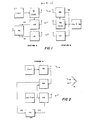
- the distance D to be measured extends between two stations, namely station A and station B.
- an instrument which is able to transmit and to receive a signal, and measurements take place by interaction between, on the one hand, a signal generated at station A and a signal transmitted to station A from station B, and, on the other hand, between a signal generated at station B and a signal transmitted to station B from station A.
- the signals are transmitted as modulation of a carrier wave of relatively high frequency, e.g. a microwave carrier or a light wave carrier.
- a transmitting source TA which produces and transmits a carrier signal at frequency fcA, frequency modulated by a pattern frequency fm, and a receiver mixer RA for receiving the signal transmitted from station B.
- the receiver mixer RA is biased by a fraction of the output of the transmitting source TA, to produce intermodulation products between the signal received from station B and the signal provided by the local oscillator bias, i.e. by the transmitting source TA.
- a transmitting source TB which produces and transmits a carrier signal at frequency fcB, frequency modulated by an auxiliary pattern frequency fm ⁇ fD, fD being a small frequency offset relative to the frequency fm.
- receiver mixer RB local oscillator biased by a fraction of the output of the transmitting source TB, to produce intermodulation products between the local oscillator bias and the signal received from station A.
- IF intermediate frequency
- the receiver mixers RA and RB each produce a comparison signal at frequency fD, the phase difference between the two comparison signals depending on the distance D and on the delay caused by passage through the respective amplifier and filters at each receiver mixer.
- the delays after mixing in the respective receiver mixers are substantially constant, being dependent on the IF frequency and the difference frequency fD only. These do not change when the pattern frequency fm is changed.
- the delays before mixing are dependent on the frequency fm as well as on the distance D and therefore change with changes in fm. This property is used to eliminate the effect of instrumental delays, as described hereinafter.
- the comparison signal obtained from the receiver mixer RB is transmitted to station A by means of a separate transmitter/ receiver link LT, LR, with LT being located at station B and LR being located at station A.
- this link is usually provided by a sub-carrier modulated on the carrier fcB, the sub-carrier itself being modulated by the comparison signal output of the receiver mixer RB, and a separate demodulator associated with the receiver mixer RA to demodulate the detected sub-carrier and to recover the comparison signal transmitted from station B to station A.
- the phase difference between the two comparison signals can now be measured at station A in a phase comparator PC. This technique is described in the aforementioned US patent 2 907 999.
- FIG 2 there is shown a system which, in essence, is the same as that of Figure 1 except that the path extending from station A to station B is 'folded' by means of a corner reflector R, with the result that stations A and B now coincide (in this embodiment referred to as station A).
- the path length being measured is now twice the distance between station A and the reflector R. Since the use of microwave frequencies for carrier waves would require a reflector of enormous size, this system is usable only if a very high carrier frequency is used, e.g. a light beam which serves as carrier for the pattern frequency fm.
- a very high carrier frequency e.g. a light beam which serves as carrier for the pattern frequency fm.
- the merging of the two stations A and B of Figure 1 into the one station A of Figure 2 permits considerable simplification.
- the pattern signal which, in the Figure 1 embodiment, is propagated from the transmitting source TA to the receiver RB is, in the Figure 2 embodiment, propagated along the measuring path.
- Propagation, in the Figure 1 embodiment, of the auxiliary pattern signal from the transmitting source TB to receiver RA, and transmission of the comparison signal along the LT, LR link is, in the Figure 2 embodiment, reduced to a simple generator which provides a signal at a frequency fm ⁇ fD.
- the one comparison signal fD is delayed along the propagation path and is recovered in RB by beating or mixing the received light beam modulated by fm, with the locally generated fm ⁇ fD signal.
- the other comparison signal fD is obtained by beating or mixing the generated fm and fm ⁇ fD signals directly, internally in RA at station A.
- Instrumental delays result in errors in the phase measurements, and are caused by phase delays in the amplifier, filter, and detector circuits which follow the respective mixers where the mixing takes place.
- instrumental delays There are two methods by which instrumental delays can be eliminated. In describing these two methods below, ap will be used to designate that part of the phase measurement resulting from the propagation delay of the pattern signal along the propagation path and any phase delays that occur before the respective mixers, whereas ai will be used to designate that part of the phase measurement resulting from instrumental delays.
- ap depends on fm
- ai depends on fD and on the IF frequency.
- phase measurements (a(plus) and a(minus)) are made at the same difference frequency fD, but originating from an auxiliary pattern frequency which, in the one case, is lower than the pattern frequency, and, in the other case, is higher than the pattern frequency.
- This has the effect of changing the direction of rotation of the phase vector ap with respect to changes in the transmission path but not to that of the phase vector ai.
- the two measurements thus obtained yield: Subtractinq the two measurements and dividinq bv two provides a phase value: which is not affected by the instrumental delay ai. Adding the two measurements and dividing by two provides a phase value: which can be used as an instrumental zero.
- phase measurements (aPr and aPx) are made, one at a reference frequency fPr, and the other at a pattern frequency fPx, but with fD substantially the same.
- the two measurements yield: Subtracting the two measurements provides: The resulting phase measurement is equal to the phase delay that would be experienced by a signal of measuring frequency without being affected by instrumental delays.
- the first method is normally used to eliminate ai from the phase measurement corresponding to the highest measuring frequency.
- the second method is used to eliminate ai from the phase measurements corresponding to the lower measuring frequencies.
- the highest measuring frequency is often selected as the reference frequency.
- the wavelength corresponding to the measuring frequency is, in this context, also referred to as the differential wavelength (Xd).
- reference numeral 10 generally indicates, in block diagram form, the circuitry of station A.
- the link LT, LR of Figure 1 is, in Figure 3, provided by a sub-carrier modulated on the carrier fcB.
- the circuitry 10 comprises means 12 for generating a microwave carrier signal at frequency fcA, means 14 for tuning the means 12 and modulating the carrier fcA, a frequency synthesiser 16 for generating any selected one of a number of accurately known pattern frequencies, a suitably programmed microprocessor 18 for controlling the operation of the synthesiser 16, display means 20 for displaying the measurements made, means 22 for permitting transmission and reception of signals by a common antenna 24, a mixer 26 for mixing the received signal with the local oscillator bias, an IF amplifier and detector 28 for detecting the first comparison signal at frequency fD and the sub-carrier modulation, a demodulator 30 for demodulating the sub-carrier to produce a second comparison signal, also at frequency fD, and a phase comparator 32 for phase comparing the two comparison signals
- Reference numeral 40 generally indicates, in block diagram form, the circuitry of station B.
- the circuitry 40 comprises means 42 for generating a microwave carrier signal at frequency fcB, means 44 for tuning the means 42 and modulating the carrier fcB, a frequency synthesiser 46 for generating the requisite auxiliary pattern frequencies, a suitably programmed microprocessor 48 for controlling the operation of the synthesiser 46, means 50 for permitting transmission and reception of signals by a common antenna 52, a mixer 54 for mixing the received signal with the local oscillator bias, an IF amplifier and detector 56 for detecting the second comparison signal fD, an oscillator 58 for generating a sub-carrier signal, and a modulator 60 in which the sub-carrier signal is modulated by the second comparison signal fD.
- the modulated sub-carrier produced by the modulator 60 is fed to the means 42, where it is modulated on the carrier fcB.
- the microprocessors 18 and 48 are suitably programmed to step the associated synthesisers 16 and 46 respectively through a sequence of frequencies which are required for the necessary measuring operations, an example of which will hereinafter be described with reference to table B.
- the microprocessors 18 and 48 are further suitably programmed to provide each phase measurement as an average over a predetermined averaging time. Averaging may take place in an analogue manner, by digital processing of data in the microprocessors, or partly in an analogue manner and partly by digital processing in the microprocessors.
- the microprocessor 18 is still further suitably programmed to provide, from a sequence of phase measurements, an indication of the distance D.
- Tables A and B at the end of this specification show a comparison between a typical conventional system (table A) and a system which is operated in accordance with the invention (table B).
- the distance D being measured extends between a static station (station S) and a mobile station (station M), and the phase measurements are made at station S.
- Each table shows a sequence of phase measurements which are required to resolve the distance unambiguously to greater than 100km under dynamic conditions, followed (after the double horizontal line in the table) by a sequence of phase measurements made when the system operates in a mode (referred to as the tracking mode) effective to track the moving station once the ambiguities have been resolved.
- the tracking mode the ambiguity factor n, once determined, is updated by carries or borrows for each full cycle of phase increase or decrease, as the case may be, measured in the tracking mode.
- the first column in each table lists the sequential number of each phase measurement, and the second column lists the time which, at the end of the particular measurement, has elapsed since the start of the sequence of measurements.
- the third column lists the pattern frequencies generated at the station S, and the fourth column the auxiliary pattern frequencies generated at the station M.
- the highest pattern frequency is referred to as fm and this is also used as the reference frequency.
- the other pattern frequencies are shown as referred to the reference frequency (fm) of the system, and are shown in such a way that it is clear how they depend on fm and P.
- the fifth column lists the measuring or differential frequencies and the sixth column their wavelengths. In relating the values of frequency and wavelength, a propagation speed of 3 x 10 8 m/sec is assumed.
- the basic parameters for the two systems are listed at the head of the respective tables.
- the switch-over time for switching from one pattern frequency to the next has been taken into account in table B and has been assumed to be 2,5ms.
- the switch-over time has been neglected, being of little account relative to the averaging time of 250ms in the system of table A.
- the fm value for the system of table A is 1,5MHz, giving a wavelength A of 100m
- the fm value for the system of table B is 15MHz, giving a wavelength A of 10m.
- the switch-over time (2,5ms) is significant in relation to the averaging time (also 2,5ms) and therefore has to be taken into account in arriving at the time taken per phase measurement (5ms).
- the averaging time also 2,5ms
- the high value of (3 in the system of table B is responsible both for the large number of phase measurements required to resolve the distance D to beyond 100km unambiguously, and for the short averaging times.
- the overall time taken by the system of table B to resolve the ambiguities is only 155ms, i.e. less than the time taken in the system of table A for one phase measurement.
- the system of table B produces 25 measurements and this improves the statistical average by ⁇ 25, resulting in a resolution for the system of table B of 0,2m, noise conditions being equal, as compared to the 1m for the system of table A.
- the maximum relative speed under which the system of table A can resolve ambiguities, assuming that there is no relative acceleration, is 0,6 ⁇ per 500ms, or 100 m/sec.
- this figure is 0,5A per 10ms, or 500 m/sec.
- the tolerance of the system of table B to relative acceleration is several orders of magnitude better than that of the system of table A. It must be borne in mind that even when tracking or measuring to a station moving at a constant speed, the relative speed can show high values of acceleration, as will be clear when considering the case of an aircraft station overflying a static measuring station where, in a very short time, the relative speed reverses in sign.
- Systems according to the invention do not only benefit when the measurement of distance takes place under dynamic conditions, but they also benefit when the measurement of distance takes place under static conditions. This is so because they are able to provide an increased measuring speed and/or increased maximum range, and reduce the sensitivity to errors resulting from multi-path reflections, thereby to reduce the incidence of errors in the resolution of ambiguities due to multi-path reflections. Such incidences, if they occur, can produce enormous errors so that the reduced risk of their occurrence will be advantageous.
- the measurements shown in Table B which, under dynamic conditions, are used for dynamic tracking, i.e. for the updating of the ambiguity factor n, may, under static conditions be used for static averaging, i.e. for improving the accuracy of the distance measurement through obtaining an average of a number of successive phase measurements.
- phase measurement refers to the difference in phase between two sinusoidally varying signals.
Landscapes
- Engineering & Computer Science (AREA)
- Radar, Positioning & Navigation (AREA)
- Remote Sensing (AREA)
- Computer Networks & Wireless Communication (AREA)
- Physics & Mathematics (AREA)
- General Physics & Mathematics (AREA)
- Radar Systems Or Details Thereof (AREA)
Claims (20)
caractérisé en ce que les fréquences modèle et modèle auxiliaire et lesdites paires de mesures de phase primaires sont sélectionnées de manière que, en oute, au moins une desdites fréquences de mesure autre que la plus élevée soit liée à la fréquence de mesure immédiatement supérieure par un facteur de multiplication p qui se trouve à l'intérieur de l'intervalle suivant:


caractérisé en ce que le moyen de commande a pour fonction de sélectionner les fréquences modèle et modèle auxiliaire et lesdites paires de mesures de phase primaires de manière que, en outre, au moins une desdites fréquences de mesure autre que la plus élevée est liée à la fréquence de mesure immédiatement supérieure par un facteur de multiplication 13 qui se trouve à l'intérieur de l'intervalle suivant:


Applications Claiming Priority (2)
| Application Number | Priority Date | Filing Date | Title |
|---|---|---|---|
| ZA823985 | 1982-06-07 | ||
| ZA823985 | 1982-06-07 |
Publications (3)
| Publication Number | Publication Date |
|---|---|
| EP0096559A2 EP0096559A2 (fr) | 1983-12-21 |
| EP0096559A3 EP0096559A3 (en) | 1985-01-09 |
| EP0096559B1 true EP0096559B1 (fr) | 1989-09-06 |
Family
ID=25576113
Family Applications (1)
| Application Number | Title | Priority Date | Filing Date |
|---|---|---|---|
| EP83303224A Expired EP0096559B1 (fr) | 1982-06-07 | 1983-06-03 | Méthode et dispositif de mesure de distance électromagnétique ou de positionnement utilisant des ondes continues |
Country Status (3)
| Country | Link |
|---|---|
| US (1) | US4646092A (fr) |
| EP (1) | EP0096559B1 (fr) |
| DE (1) | DE3380529D1 (fr) |
Families Citing this family (17)
| Publication number | Priority date | Publication date | Assignee | Title |
|---|---|---|---|---|
| US4829305A (en) * | 1985-03-29 | 1989-05-09 | Lubudde Engineering Corporation | Medium distance measurement system and method |
| US4908627A (en) * | 1985-06-14 | 1990-03-13 | Santos James P | Monitoring, ranging and locating devices |
| SE456118B (sv) * | 1985-12-12 | 1988-09-05 | Stiftelsen Inst Mikrovags | Forfarande och anordning for att meta avstand mellan ett forsta och ett andra foremal med signaler av mikrovagsfrekvens |
| SE456867B (sv) * | 1985-12-12 | 1988-11-07 | Stiftelsen Inst Mikrovags | Saett att uppmaeta avstaand och/eller hastighet mellan tvaa foeremaal |
| US5293160A (en) * | 1989-11-02 | 1994-03-08 | Nissan Motor Company, Ltd. | Keyless vehicle lock system with distance measuring |
| US5191328A (en) * | 1990-06-13 | 1993-03-02 | Donald L. Gambill | Trailer hitching aid and method using reception delay of different velocity signals |
| US5706010A (en) * | 1996-05-16 | 1998-01-06 | E-Systems, Inc. | Method and apparatus for determining location of an unknown signal transmitter |
| GB2315943A (en) * | 1996-08-01 | 1998-02-11 | Paul Michael Wood | Distance measuring system |
| JP4332255B2 (ja) * | 1999-05-14 | 2009-09-16 | 株式会社トプコン | 距離測定装置 |
| DE19963625A1 (de) * | 1999-12-29 | 2001-07-12 | Bosch Gmbh Robert | Verfahren zur Messung des Abstands und der Geschwindigkeit von Objekten |
| DE10249866B4 (de) * | 2002-10-25 | 2012-02-16 | Continental Automotive Gmbh | Vorrichtung zur Positionsbestimmung wenigstens einer zweiten Sende- und Empfangseinrichtung bezüglich einer ersten Sende- und Empfangseinrichtung in einem GHz-Bereich arbeitenden passiven Zugangskontrollsystem |
| US7490817B2 (en) * | 2005-01-04 | 2009-02-17 | Bfs Diversified Products Llc | Distance indicating system and method |
| US7364144B2 (en) * | 2005-04-27 | 2008-04-29 | Bfs Diversified Products, Llc | Sensing and communication system and method |
| US7420462B2 (en) * | 2006-01-23 | 2008-09-02 | Bfs Diversified Products, Llc | Air spring distance indicating system and method |
| US7733239B2 (en) * | 2006-05-08 | 2010-06-08 | Bfs Diversified Products, Llc | Distance determining system and method |
| CN101275999B (zh) * | 2007-03-28 | 2011-10-12 | 王海舟 | 交通通信测距方法和系统 |
| US8723720B2 (en) * | 2011-05-03 | 2014-05-13 | Harris Corporation | Wireless location detection and/or tracking device and associated methods |
Family Cites Families (3)
| Publication number | Priority date | Publication date | Assignee | Title |
|---|---|---|---|---|
| FR1295040A (fr) * | 1961-05-29 | 1962-06-01 | Cubic Corp | Système d'arpentage électronique pour mesurer la distance entre deux points espacés |
| US3315257A (en) * | 1964-08-12 | 1967-04-18 | Gerhard P Sauberlich | Apparatus and method for geodeticsurveying system |
| US4307397A (en) * | 1977-12-05 | 1981-12-22 | The South African Inventions Development Corporation | Method of and apparatus for measuring distance |
-
1983
- 1983-05-26 US US06/498,469 patent/US4646092A/en not_active Expired - Fee Related
- 1983-06-03 DE DE8383303224T patent/DE3380529D1/de not_active Expired
- 1983-06-03 EP EP83303224A patent/EP0096559B1/fr not_active Expired
Also Published As
| Publication number | Publication date |
|---|---|
| EP0096559A3 (en) | 1985-01-09 |
| US4646092A (en) | 1987-02-24 |
| DE3380529D1 (en) | 1989-10-12 |
| EP0096559A2 (fr) | 1983-12-21 |
Similar Documents
| Publication | Publication Date | Title |
|---|---|---|
| EP0096559B1 (fr) | Méthode et dispositif de mesure de distance électromagnétique ou de positionnement utilisant des ondes continues | |
| US4594676A (en) | Aircraft groundspeed measurement system and technique | |
| EP0404833B1 (fr) | Recepteur d'estimation de la position relative d'un avion dans le systeme tcas, utilisant une antenne a quatre elements | |
| EP0264440B1 (fr) | Procede et dispositif de positionnement differentiel dynamique de precision | |
| US3946385A (en) | Interferometric navigation and guidance system | |
| EP0138940B1 (fr) | Procede et appareil de mesure de la distance d'un objet | |
| US6147640A (en) | Communications satellite interference location system | |
| US3697997A (en) | Interferometer and angle encoding navigation system | |
| US4339755A (en) | Passive-type range determining system using scanning receiving devices | |
| US4635060A (en) | Coherent-on-receive radar with prephase correction circuit | |
| US3838424A (en) | Microwave interference pattern sensor | |
| US4999638A (en) | Apparatus and method for synchronizing the signal averaging clock of a Loran C. receiver to the clock of a Loran C. transmitter | |
| EP1509784A1 (fr) | Procedes et dispositifs pour detection de phase precise | |
| EP0315411B1 (fr) | Système de localisation | |
| US4301455A (en) | Groundspeed measurement system | |
| US4888594A (en) | Loran-C receiver module | |
| US3634862A (en) | Precision approach and landing system | |
| US4485384A (en) | Microwave system | |
| US3790940A (en) | Communication apparatus having a ranging capability | |
| US3344423A (en) | Control apparatus | |
| US5955971A (en) | Window-passage detection system of an airplane | |
| GB2096854A (en) | Improvements in and relating to direction finding systems | |
| US4131890A (en) | Spectral analysis | |
| US4109249A (en) | Scanning beam receiver | |
| US3235865A (en) | Calibration correcting system for doppler navigators |
Legal Events
| Date | Code | Title | Description |
|---|---|---|---|
| PUAI | Public reference made under article 153(3) epc to a published international application that has entered the european phase |
Free format text: ORIGINAL CODE: 0009012 |
|
| AK | Designated contracting states |
Designated state(s): DE FR GB |
|
| PUAL | Search report despatched |
Free format text: ORIGINAL CODE: 0009013 |
|
| AK | Designated contracting states |
Designated state(s): DE FR GB |
|
| 17P | Request for examination filed |
Effective date: 19850624 |
|
| 17Q | First examination report despatched |
Effective date: 19870805 |
|
| GRAA | (expected) grant |
Free format text: ORIGINAL CODE: 0009210 |
|
| AK | Designated contracting states |
Kind code of ref document: B1 Designated state(s): DE FR GB |
|
| REF | Corresponds to: |
Ref document number: 3380529 Country of ref document: DE Date of ref document: 19891012 |
|
| ET | Fr: translation filed | ||
| PLBE | No opposition filed within time limit |
Free format text: ORIGINAL CODE: 0009261 |
|
| STAA | Information on the status of an ep patent application or granted ep patent |
Free format text: STATUS: NO OPPOSITION FILED WITHIN TIME LIMIT |
|
| 26N | No opposition filed | ||
| PGFP | Annual fee paid to national office [announced via postgrant information from national office to epo] |
Ref country code: FR Payment date: 19950505 Year of fee payment: 13 |
|
| PGFP | Annual fee paid to national office [announced via postgrant information from national office to epo] |
Ref country code: DE Payment date: 19950830 Year of fee payment: 13 |
|
| PGFP | Annual fee paid to national office [announced via postgrant information from national office to epo] |
Ref country code: GB Payment date: 19960628 Year of fee payment: 14 |
|
| PG25 | Lapsed in a contracting state [announced via postgrant information from national office to epo] |
Ref country code: FR Effective date: 19970228 |
|
| PG25 | Lapsed in a contracting state [announced via postgrant information from national office to epo] |
Ref country code: DE Effective date: 19970301 |
|
| REG | Reference to a national code |
Ref country code: FR Ref legal event code: ST |
|
| PG25 | Lapsed in a contracting state [announced via postgrant information from national office to epo] |
Ref country code: GB Effective date: 19970603 |
|
| GBPC | Gb: european patent ceased through non-payment of renewal fee |
Effective date: 19970603 |