EP0096595A1 - Embrayage compact - Google Patents
Embrayage compact Download PDFInfo
- Publication number
- EP0096595A1 EP0096595A1 EP83303320A EP83303320A EP0096595A1 EP 0096595 A1 EP0096595 A1 EP 0096595A1 EP 83303320 A EP83303320 A EP 83303320A EP 83303320 A EP83303320 A EP 83303320A EP 0096595 A1 EP0096595 A1 EP 0096595A1
- Authority
- EP
- European Patent Office
- Prior art keywords
- clutch
- drum
- piston
- disc
- cylinder
- Prior art date
- Legal status (The legal status is an assumption and is not a legal conclusion. Google has not performed a legal analysis and makes no representation as to the accuracy of the status listed.)
- Withdrawn
Links
- 230000004323 axial length Effects 0.000 claims abstract description 8
- 230000000694 effects Effects 0.000 claims abstract description 6
- 239000012530 fluid Substances 0.000 claims description 9
- 230000005540 biological transmission Effects 0.000 description 2
- 238000006243 chemical reaction Methods 0.000 description 1
- 230000008878 coupling Effects 0.000 description 1
- 238000010168 coupling process Methods 0.000 description 1
- 238000005859 coupling reaction Methods 0.000 description 1
Images
Classifications
-
- F—MECHANICAL ENGINEERING; LIGHTING; HEATING; WEAPONS; BLASTING
- F16—ENGINEERING ELEMENTS AND UNITS; GENERAL MEASURES FOR PRODUCING AND MAINTAINING EFFECTIVE FUNCTIONING OF MACHINES OR INSTALLATIONS; THERMAL INSULATION IN GENERAL
- F16D—COUPLINGS FOR TRANSMITTING ROTATION; CLUTCHES; BRAKES
- F16D25/00—Fluid-actuated clutches
- F16D25/06—Fluid-actuated clutches in which the fluid actuates a piston incorporated in, i.e. rotating with the clutch
- F16D25/062—Fluid-actuated clutches in which the fluid actuates a piston incorporated in, i.e. rotating with the clutch the clutch having friction surfaces
- F16D25/063—Fluid-actuated clutches in which the fluid actuates a piston incorporated in, i.e. rotating with the clutch the clutch having friction surfaces with clutch members exclusively moving axially
Definitions
- This invention relates generally to a clutch. More particularly, it relates to a compact clutch which provides high torque capacity but which occupies a short axial length. Such a compact clutch is adapted for use, for example, in a front-wheel-drive automotive vehicle incorporating a continuously variable transmission (CVT).
- CVT continuously variable transmission
- Clutch diameter is a critical dimension in the typical transmission used in a rear-wheel-drive vehicle. As automotive vehicles are downsized, considerable work is being directed to the application of the CVT to front-wheel-drive vehicles. It is becoming clear that in this environment space constraints relate to clutch length rather than diameter.
- one aspect of the present invention comprises a clutch as set out in claim 1.
- Another aspect of the invention provides the clutch as set out in claim 3.
- the piston slides a tension member, in the form of a clutch drum, over a fixed clutch spine in order to effect clutch engagement.
- Orientation of the cylinder and piston relatively close to the axis of rotation minimizes the effect of centrifugal force while orientation of the clutch plates relatively far from the axis of rotation maximizes the torque capacity of the clutch.
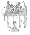
- CVT 10 includes a pulley 12 which may be the output pulley of a belt/pulley assembly. Pulley 12 drives a shaft 14 about an axis A.
- CVT 10 includes suitable means 16 for coupling shaft 14 with a quill 18 journalled on shaft 14 for rotation about axis A.
- the compact clutch 20 of this invention includes an input member 22 in the form of a clutch spine.
- Spine 22 is fixed axially, and defines a hub 24 secured to quill 18 for rotation therewith.
- Spine 22 also defines a cylinder 26 oriented radially outwardly of hub 24 and, outwardly of cylinder 26, a disc 28 with a plurality of teeth 30 at its outermost end.
- a reaction member 32 Also extending outwardly from hub 24 is a reaction member 32.
- Cylinder 26 is in communication with a controlled source of fluid pressure (not shown) by means of a fluid passage 34 extending through hub 24, quill 18, shaft 14 and a suitable fluid line 36.
- a piston 38 is axially slidable within cylinder 26. Piston 38 defines a radially outwardly-extending disc 40 adjacent disc 28 of spine 22. A suitable spring 42 reacts against member 32 and acts upon piston 38 to bias it leftwardly as shown in the drawing. Spine 22, piston 38 and spring 42 together define clutch actuating means 43.
- a clutch drum 44 is secured at one end thereof to the outermost end of disc 40 by a snap ring 46.
- Drum 44 defines a plurality of axially oriented slots 48 into which loosely extend teeth 30 of spine 22.
- a clutch backing plate 50 and at least one clutch separator plate 52 extend inwardly from slots 48. At its other end, drum 44 terminates in an inwardly-extending clutch pressure plate 54.
- An output member 56 includes a disc 58 and a ring 60 oriented between cylinder 26 and drum 44. Ring 60 defines a spline 62. A plurality of clutch friction plates 64 extend outwardly from spline 62 into axial alignment with clutch plates 50, 52 and 54.
- Disc 58 is secured to a gear 66 or the like journalled on quill 18 for rotation about axis A.
- gear 66 may be in driving engagement with suitable reduction means 68 forming the input to a conventional differential and/or drive axle.
- a torque delivery path in the forward direction may be provided by disengaging clutch 20 and engaging a reversing mechanism 70.
- Reversing mechanism 70 includes a sun gear 72 secured to quill 18.
- a ring gear 74 is engageable by a brake 76 with the housing 78 of CVT 10.
- a carrier 80 is splined to gear 66.
- Carrier 80 supports a plurality of planet gears 82 (one of which is shown in the drawing) in meshing relationship with sun gear 72 and ring gear 74.
- a suitable fluid line 84 communicates a controlled source of fluid pressure (not shown) with a cylinder 86 in order to control the movement of a piston 88 so as to selectively engage brake 76.
- An important feature of this invention is the arrangement of clutch 20 such that hub 24, cylinder 26 and piston 38 are in substantial radial alignment with clutch plates 50, 52, 54 and 64. That is, they are nested within these plates to thereby provide a compact clutch having a minimum axial length.
- Another important feature of this invention is the orientation of cylinder 26 and piston 38 radially inwardly of the clutch plates and thus relatively close to axis A. This minimizes the effect of centrifugal force on clutch operation, which effect could be a tendency to overcome the control pressure and cause an undesriable clutch engagement. With this orientation, there may not be any requirement for ball check valves, counter-balancing dams, etc.
- Yet another important feature of this invention is the orientation of the clutch plates at the radially outermost position possible. This allows for the largest possible friction surface area, and thus maximizes the torque capacity of clutch 20. As noted above, this high torque capacity is provided in a clutch having a short axial length.
- the invention disclosed herein provides an inexpensive, compact clutch which may be formed from simple stampings.
- the compact clutch has high torque capacity while occuping a short axial length.
- the compact clutch of this invention be restricted in its application to an automotive environment in general or a CVT in particular. Rather, it is contemplated that the compact clutch may be utilized in a wide variety of applications where high torque capacity and short axial length are desirable.
Landscapes
- Engineering & Computer Science (AREA)
- General Engineering & Computer Science (AREA)
- Mechanical Engineering (AREA)
- Hydraulic Clutches, Magnetic Clutches, Fluid Clutches, And Fluid Joints (AREA)
Applications Claiming Priority (2)
| Application Number | Priority Date | Filing Date | Title |
|---|---|---|---|
| GB8217159 | 1982-06-14 | ||
| GB08217159A GB2122281A (en) | 1982-06-14 | 1982-06-14 | Compact clutch |
Publications (1)
| Publication Number | Publication Date |
|---|---|
| EP0096595A1 true EP0096595A1 (fr) | 1983-12-21 |
Family
ID=10531019
Family Applications (1)
| Application Number | Title | Priority Date | Filing Date |
|---|---|---|---|
| EP83303320A Withdrawn EP0096595A1 (fr) | 1982-06-14 | 1983-06-08 | Embrayage compact |
Country Status (5)
| Country | Link |
|---|---|
| EP (1) | EP0096595A1 (fr) |
| JP (1) | JPS596428A (fr) |
| AU (1) | AU1523583A (fr) |
| BR (1) | BR8303131A (fr) |
| GB (1) | GB2122281A (fr) |
Cited By (1)
| Publication number | Priority date | Publication date | Assignee | Title |
|---|---|---|---|---|
| EP0207685A1 (fr) * | 1985-07-01 | 1987-01-07 | Borg-Warner Automotive, Inc. | Dispositif d'embrayage de démarrage pour une transmission continue variable |
Citations (12)
| Publication number | Priority date | Publication date | Assignee | Title |
|---|---|---|---|---|
| FR908979A (fr) * | 1944-08-12 | 1946-04-24 | Embrayage à disques multiples | |
| US2656905A (en) * | 1945-08-13 | 1953-10-27 | Western Gear Works | Fluid operated friction clutch |
| US3016121A (en) * | 1959-05-28 | 1962-01-09 | Roper Hydraulics Inc | Hydraulically operated clutch |
| US3064780A (en) * | 1958-05-14 | 1962-11-20 | Borg Warner | Hydraulic clutch |
| DE1181011B (de) * | 1957-04-06 | 1964-11-05 | Maybach Motorenbau Gmbh | Durch Druckfluessigkeit schaltbare Lamellenkupplung |
| FR1460372A (fr) * | 1964-12-30 | 1966-11-25 | Borg Warner | Embrayages connectant un compresseur de conditionnement d'air au moteur d'un véhicule |
| DE1256966B (de) * | 1959-12-24 | 1967-12-21 | Ortlinghaus Geb | Druckmittelbetaetigte Lamellenkupplung |
| GB1104851A (en) * | 1965-03-10 | 1968-03-06 | Belorusky Avtomobilny Zd | A power take-off drive |
| US3823802A (en) * | 1972-08-18 | 1974-07-16 | Caterpillar Tractor Co | Clutch with controlled coolant flow |
| FR2276501A1 (fr) * | 1974-06-28 | 1976-01-23 | Motoren Turbinen Union | Accouplement a disques |
| DE2818808A1 (de) * | 1978-04-28 | 1979-11-08 | Klaue Hermann | Schaltkupplung fuer kupplungsschaltgetriebe, insbesondere fuer kraftfahrzeuge |
| FR2432647A1 (fr) * | 1978-08-03 | 1980-02-29 | Zahnradfabrik Friedrichshafen | Dispositif a ressort de freinage ou d'accouplement actionne hydrauliquement |
Family Cites Families (1)
| Publication number | Priority date | Publication date | Assignee | Title |
|---|---|---|---|---|
| DE1600017A1 (de) * | 1966-07-14 | 1970-04-02 | Ortlinghaus Geb Ohg | Kombinierte druckmittelbetaetigte Kupplungs- und Bremsvorrichtung |
-
1982
- 1982-06-14 GB GB08217159A patent/GB2122281A/en not_active Withdrawn
-
1983
- 1983-05-31 AU AU15235/83A patent/AU1523583A/en not_active Abandoned
- 1983-06-08 EP EP83303320A patent/EP0096595A1/fr not_active Withdrawn
- 1983-06-13 BR BR8303131A patent/BR8303131A/pt unknown
- 1983-06-13 JP JP58105635A patent/JPS596428A/ja active Pending
Patent Citations (12)
| Publication number | Priority date | Publication date | Assignee | Title |
|---|---|---|---|---|
| FR908979A (fr) * | 1944-08-12 | 1946-04-24 | Embrayage à disques multiples | |
| US2656905A (en) * | 1945-08-13 | 1953-10-27 | Western Gear Works | Fluid operated friction clutch |
| DE1181011B (de) * | 1957-04-06 | 1964-11-05 | Maybach Motorenbau Gmbh | Durch Druckfluessigkeit schaltbare Lamellenkupplung |
| US3064780A (en) * | 1958-05-14 | 1962-11-20 | Borg Warner | Hydraulic clutch |
| US3016121A (en) * | 1959-05-28 | 1962-01-09 | Roper Hydraulics Inc | Hydraulically operated clutch |
| DE1256966B (de) * | 1959-12-24 | 1967-12-21 | Ortlinghaus Geb | Druckmittelbetaetigte Lamellenkupplung |
| FR1460372A (fr) * | 1964-12-30 | 1966-11-25 | Borg Warner | Embrayages connectant un compresseur de conditionnement d'air au moteur d'un véhicule |
| GB1104851A (en) * | 1965-03-10 | 1968-03-06 | Belorusky Avtomobilny Zd | A power take-off drive |
| US3823802A (en) * | 1972-08-18 | 1974-07-16 | Caterpillar Tractor Co | Clutch with controlled coolant flow |
| FR2276501A1 (fr) * | 1974-06-28 | 1976-01-23 | Motoren Turbinen Union | Accouplement a disques |
| DE2818808A1 (de) * | 1978-04-28 | 1979-11-08 | Klaue Hermann | Schaltkupplung fuer kupplungsschaltgetriebe, insbesondere fuer kraftfahrzeuge |
| FR2432647A1 (fr) * | 1978-08-03 | 1980-02-29 | Zahnradfabrik Friedrichshafen | Dispositif a ressort de freinage ou d'accouplement actionne hydrauliquement |
Cited By (1)
| Publication number | Priority date | Publication date | Assignee | Title |
|---|---|---|---|---|
| EP0207685A1 (fr) * | 1985-07-01 | 1987-01-07 | Borg-Warner Automotive, Inc. | Dispositif d'embrayage de démarrage pour une transmission continue variable |
Also Published As
| Publication number | Publication date |
|---|---|
| BR8303131A (pt) | 1984-01-31 |
| AU1523583A (en) | 1984-01-05 |
| GB2122281A (en) | 1984-01-11 |
| JPS596428A (ja) | 1984-01-13 |
Similar Documents
| Publication | Publication Date | Title |
|---|---|---|
| US4467670A (en) | Belt drive continuously-variable speed automatic transmission | |
| EP0640773B1 (fr) | Dispositif d'engagement à friction pour une transmission automatique | |
| EP1079132B1 (fr) | Transmission automatique avec dispositif de friction à deux étapes | |
| US4177885A (en) | Torque converter and lock-up clutch | |
| EP0282169A1 (fr) | Unité d'embrayage avec chambre de compensation de pression | |
| US4890510A (en) | Center differential for four-wheel drive vehicle | |
| US4978328A (en) | Automatic transaxle assembly for an automotive vehicle driveline | |
| GB1574669A (en) | Torque converter and lockup clutch assemblies | |
| US4951788A (en) | Torque converter multiplate bypass clutch | |
| US6648117B2 (en) | Starting clutch and method for controlling same | |
| US8434607B2 (en) | Compact torque transmitting assembly | |
| US5913397A (en) | Clutch structure with piston having surface recessed from pressure surface for reducing stress concentration | |
| US7083537B2 (en) | Multiple speed automatic transmission for motor vehicle | |
| US20050245346A1 (en) | Bi-directional four-mode clutch for providing low and reverse gear ratios in a transmission | |
| US5511642A (en) | Overrunning clutch assembly | |
| EP0506015A1 (fr) | Dispositif de transmission du couple moteur d'un véhicule à quatre roues motrices | |
| EP0810393A2 (fr) | Transmission automatique de véhicule avec dispositif de freinage pour marche arrière | |
| EP1205337B1 (fr) | Dispositif de restriction de différentiel | |
| US3677381A (en) | Hydraulic clutch with dump valve | |
| US20190293129A1 (en) | Frictional coupling device of vehicular power transmitting system | |
| US4947969A (en) | Center load clutch brake | |
| EP0096595A1 (fr) | Embrayage compact | |
| US5857549A (en) | Torque transmitting device with a lever apply spring | |
| CN113446326A (zh) | 带有锥形表面的离合器总成压盘 | |
| US3688882A (en) | Fluid operated clutch with one way engager |
Legal Events
| Date | Code | Title | Description |
|---|---|---|---|
| PUAI | Public reference made under article 153(3) epc to a published international application that has entered the european phase |
Free format text: ORIGINAL CODE: 0009012 |
|
| AK | Designated contracting states |
Designated state(s): DE FR GB IT NL |
|
| RAP1 | Party data changed (applicant data changed or rights of an application transferred) |
Owner name: BORG-WARNER LIMITED |
|
| 17P | Request for examination filed |
Effective date: 19840404 |
|
| STAA | Information on the status of an ep patent application or granted ep patent |
Free format text: STATUS: THE APPLICATION HAS BEEN WITHDRAWN |
|
| 18W | Application withdrawn |
Withdrawal date: 19850523 |
|
| RIN1 | Information on inventor provided before grant (corrected) |
Inventor name: GARDNER, DEREK |