EP0096706B1 - Brechmaschinen zur zerkleinerung von mineralien - Google Patents
Brechmaschinen zur zerkleinerung von mineralien Download PDFInfo
- Publication number
- EP0096706B1 EP0096706B1 EP83900287A EP83900287A EP0096706B1 EP 0096706 B1 EP0096706 B1 EP 0096706B1 EP 83900287 A EP83900287 A EP 83900287A EP 83900287 A EP83900287 A EP 83900287A EP 0096706 B1 EP0096706 B1 EP 0096706B1
- Authority
- EP
- European Patent Office
- Prior art keywords
- drum
- teeth
- mineral
- tooth
- breaker
- Prior art date
- Legal status (The legal status is an assumption and is not a legal conclusion. Google has not performed a legal analysis and makes no representation as to the accuracy of the status listed.)
- Expired
Links
- 229910052500 inorganic mineral Inorganic materials 0.000 title claims abstract description 58
- 239000011707 mineral Substances 0.000 title claims abstract description 58
- 230000015572 biosynthetic process Effects 0.000 claims abstract description 40
- 238000005755 formation reaction Methods 0.000 claims abstract description 40
- 238000011068 loading method Methods 0.000 claims description 12
- 230000000295 complement effect Effects 0.000 claims description 8
- 239000000463 material Substances 0.000 description 14
- 238000010276 construction Methods 0.000 description 7
- 229910000831 Steel Inorganic materials 0.000 description 2
- 238000013019 agitation Methods 0.000 description 2
- 230000000712 assembly Effects 0.000 description 2
- 238000000429 assembly Methods 0.000 description 2
- 238000005056 compaction Methods 0.000 description 2
- 230000000694 effects Effects 0.000 description 2
- 239000010959 steel Substances 0.000 description 2
- 238000003466 welding Methods 0.000 description 2
- MBEVSMZJMIQVBG-UHFFFAOYSA-N 2-(hydroxymethyl)guanidine Chemical compound NC(N)=NCO MBEVSMZJMIQVBG-UHFFFAOYSA-N 0.000 description 1
- 239000013070 direct material Substances 0.000 description 1
- 238000004519 manufacturing process Methods 0.000 description 1
- 239000002184 metal Substances 0.000 description 1
- 239000011236 particulate material Substances 0.000 description 1
- 230000002093 peripheral effect Effects 0.000 description 1
- 238000004513 sizing Methods 0.000 description 1
- 230000003019 stabilising effect Effects 0.000 description 1
- 230000003068 static effect Effects 0.000 description 1
Images







Classifications
-
- B—PERFORMING OPERATIONS; TRANSPORTING
- B02—CRUSHING, PULVERISING, OR DISINTEGRATING; PREPARATORY TREATMENT OF GRAIN FOR MILLING
- B02C—CRUSHING, PULVERISING, OR DISINTEGRATING IN GENERAL; MILLING GRAIN
- B02C18/00—Disintegrating by knives or other cutting or tearing members which chop material into fragments
- B02C18/06—Disintegrating by knives or other cutting or tearing members which chop material into fragments with rotating knives
- B02C18/14—Disintegrating by knives or other cutting or tearing members which chop material into fragments with rotating knives within horizontal containers
- B02C18/146—Disintegrating by knives or other cutting or tearing members which chop material into fragments with rotating knives within horizontal containers with a rotor comprising a plurality of axially contiguous disc-like segments each having at least one radially extending cutting element
-
- B—PERFORMING OPERATIONS; TRANSPORTING
- B02—CRUSHING, PULVERISING, OR DISINTEGRATING; PREPARATORY TREATMENT OF GRAIN FOR MILLING
- B02C—CRUSHING, PULVERISING, OR DISINTEGRATING IN GENERAL; MILLING GRAIN
- B02C18/00—Disintegrating by knives or other cutting or tearing members which chop material into fragments
- B02C18/06—Disintegrating by knives or other cutting or tearing members which chop material into fragments with rotating knives
- B02C18/14—Disintegrating by knives or other cutting or tearing members which chop material into fragments with rotating knives within horizontal containers
- B02C18/142—Disintegrating by knives or other cutting or tearing members which chop material into fragments with rotating knives within horizontal containers with two or more inter-engaging rotatable cutter assemblies
Definitions
- the present invention relates to a mineral breaker.
- the present invention aims to produce a mineral breaker of the above type wherein a breaker. tooth construction is provided which enables the breaker to handle relatively large lumps of a hard mineral.
- a mineral breaker having at least one breaker drum (15) including a plurality of breaker teeth (20) projecting radially from the drum and further including a plurality of opposed breaker teeth positioned so that on rotation of the drum mineral lumps to be broken are gripped between the leading face of the teeth of the drum and a pair of said opposed breaker teeth to thereby break the mineral lump gripped therebetween by a snapping action
- the breaker teeth (20) mounted on the breaker drum each comprise a main tooth body (34) in the form of a projection projecting from the drum and a sheath (40) removably mounted on the tooth body, the sheath including a hollow tooth formation (45) which defines the external shape of the tooth and which includes a pocket which is seated on and fully envelopes the tooth body, the shape of the tooth body and the pocket being complementary so that when the sheath is seated on the tooth body the leading (150) and trailing faces (53) of the tooth body and the respective facing internal walls of the pocket are
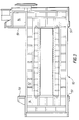
- the sizer 10 includes a housing 11 having sides 12 and end walls 14.
- the housing 11 is conveniently fabricated from steel plate panels which are bolted and welded together.
- Rotatably mounted to extend between the end walls 14 are a pair of breaker drum assemblies 15 each of which is geared at one end to the other so that they are driven from a common drive 18 to be rotated in opposite directions, In the embodiment illustrated in Figure 1 the drums are rotated so as to direct material between them.
- the gear connection between the drums also serves to set the rotary positions of the drums relative to one another.
- Each drum assembly 15 is provided with circumferentially extending groups 19 of breaker teeth 20, the groups 19 being spaced axially along the drum assembly 15.
- the axial spacing of groups 19 on one drum assembly is staggered to that on the other drum assembly so the teeth 20 in a group 19 on one drum assembly pass between an adjacent pair of groups 19 on the other drum assembly.
- the teeth 20 are also preferably arranged to define a series of discrete helical formations 21 which are spaced circumferentially about each drum assembly 15.
- the helical formations 21 as shown in Figures 1 and 7 extend along the axes of each drum in a different sense, i.e. for the left hand drum as seen in Figure 1 the helical formations 21 extend away from the nearest end wall 14 in an anti-clockwise sense and for the right hand drum the helical formations 21 extend in a clockwise sense.
- each helical formation 21 in extending along its respective drum passes through an arc of about 90°.
- teeth 20 and their relative positions and size are such that during use, two types of breaking action are present, viz a primary breaking action on larger pieces of mineral whereat the mineral is gripped between opposing leading faces 46 of teeth on opposite drums and a secondary breaking action wherein mineral is trapped between the rear edges 47 of teeth and the leading face 46 of another tooth.
- a primary breaking action on larger pieces of mineral whereat the mineral is gripped between opposing leading faces 46 of teeth on opposite drums
- a secondary breaking action wherein mineral is trapped between the rear edges 47 of teeth and the leading face 46 of another tooth.
- the arc through which each helical formation passes is such as to ensure that a secondary breaking action occurs.
- the spacing between the drums is chosen so that when the tips of teeth on one drum sweep past the trough defined between groups 19 of teeth on the other drum there is sufficient clearance so that compaction of material is avoided. Accordingly by a suitable choice of spacing it is possible for fine material to quickly pass through the sizer without compaction, thus leaving the sizer to break down larger pieces of material either by the primary and/or secondary breaking action.
- teeth 20 are designed bearing in mind the hardness and tensile strength of the . mineral to be broken.
- the teeth are designed to provide as much bite as possible for the primary type of breaking action for the diameter of the drum assembly so as to positively grip large pieces of material.
- the ratio of height of teeth relative to drum diameter is normally large.
- the tooth height to diameter of drum ratio can be 1:4.
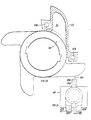
- the cross-sectional extent of a bite region 70 for primary breaking is illustrated in Figure 6, the depth of the region 70 is defined by the trailing edge 47 of one tooth and the leading edge 46 of a succeeding tooth; and the length of the region 70 is defined between the leading face 46 of one tooth and the leading face 46' of an opposed tooth on the opposite drum.
- the trailing edge 47 which is slightly curved, but which may be straight if desired, is chosen to be approximately tangential to the drum diameter and the leading face 46 is chosen to be approximately located radially relative to the drum.
- the grip region between teeth on the same group may be varied to alter the size of the grip region by either altering the size of tooth or by altering the number of teeth in each group 19, the maximum grip region being achieved when the point of intersection of face 46 is on or behind (in the direction of rotation of the drum) the location whereat the trailing edge of the preceding tooth merges into the periphery of the drum.
- a further advantage resulting from the actions imposed on a large piece of material by the helical formations is that the large piece is positively moved along the axes of the d.rums thereby permitting smaller pieces to pass downwardly thereby and pass through the m'ineral breaker. Accordingly the mineral breaker is able to handle an in-fill of mineral which contains a large variation in size such as mineral obtained in open- cast quarrying which contains small particulate material as well as large lumps of mineral.
- the teeth impose tensile breaking forces onto the mineral and so positively breaks the material with minimal production of fines. Additionally since each tooth passes between groups of teeth on the opposite drum positive sizing of mineral occurs since the maximum size of mineral passing through the sizer is determined by the space between the trailing edge 47 of one tooth and the leading face 46 of a succeeding tooth and the distance between adjacent groups 19 of teeth. Therefore if the in-fill material contains only large pieces of mineral the mineral on leaving the sizer will contain no pieces over a predetermined size and will contain a small quantity of fines.
- the breaker drums may be inclined to the horizontal and arranged so that large pieces of mineral are made to climb up the incline by the helical formations. Due to the agitation of the large piece of mineral it is likely to fall down the incline and is accordingly repeatedly moved along the drums until it has been broken down sufficiently to be broken by the secondary breaking action.
- the mineral sizer according to the present invention is normally located above a takeaway conveyor TC so that the axes of the drums are generally parallel to the direction of travel of the conveyor TC.
- the sizer By setting the sizer so that the spacing between the drums is generally located above the longitudinal axis of the conveyor material being deposited by the sizer onto the conveyor TC is arranged centrally thereon. This is advantageous as it minimises spillage.
- each drum assembly 15 is shown in longitudinal section in Figure 4 and includes a stepped shaft 25 on which is keyed a support sleeve 26 made up of three support sleeve portions 26a, b and c.
- the centre sleeve 26b is of larger internal diameter so that it can be easily slid over most of the shaft 25 during assembly and disassembly.
- the sleeve portions 26a, b and c are fixedly secured to one another by weld lines 26d so as to form an integral sleeve 26 running the majority of the length of the shaft 25.
- Aseries of annular support rings 28 are mounted on each sleeve 26 and are secured to one another and also to sleeve 26 by weld lines 30.
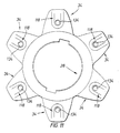
- Each ring 28 has a series of teeth support projections 34 integrally formed therewith which are spaced circumferentially about its periphery.
- Each ring 28 is conveniently formed from a cast metal.
- each ring 28 may be easily set during assembly to align or stagger the teeth support projections 34 of adjacent rings 28 by rotating the rings 28 on sleeve 26 and then fixedly securing them in that position.
- the projections 34 on adjacent rings 28 have been set so that the projections form longitudinally extending rows which are substantially parallel to the axis of rotation of the drum assembly 15 in contrast to the arrangement in Figure 1 wherein adjacent rings 28 have been set so that the projections 34 form the longitudinally extending helical formations 21.
- each ring 28 is therefore only in abutment with its neighbour and the assembly of rings 28 are prevented from axial movement by virtue of a shoulder 25x and a removable collar 25z. Accordingly should the shaft or a ring become damaged during use, the shaft and ring assembly may be disassembled for replacement of the damaged component. It will be appreciated that each ring may be easily angularly offset to its neighbour to provide the desired helical formation 21, the amount of offsetting being determined in steps dictated by the pitch of the splines.
- a further alternative is to cast the series of annular support rings and shaft integrally with one another.
- a tooth sheath 40 is secured to each projection 34 via a bolt 41, or other similar means such as a sprung spigot, which is located in pockets 42 in the sheath and are thus protected from damage during use.
- a bolt 41 or other similar means such as a sprung spigot, which is located in pockets 42 in the sheath and are thus protected from damage during use.
- all sheaths When all sheaths are in position they collectively form a cover over adjacent rings 28 so that the rings are protected from wear by mineral being sized.
- Each sheath 40 has an annular base portion 43 which follows the contour of ring 28 and a hollow tooth portion 45 integrally connected to the base portion 43.
- the tooth portion 45 has an internal pocket which is of a complementary shape to a projection 34 so when the tooth portion is seated upon a projection, loads imparted onto the tooth portion 45 during use are transmitted onto the projection 34.
- each tooth is exposed to two main sources of loadings; firstly a loading on its leading face 46 resulting from a primary or secondary breaking action and secondly a loading on its trailing edge 47 resulting from a secondary breaking action.
- the shape of projection 34 and that of tooth portion 45 is chosen so that when the tooth is exposed to the first type of loading the face 46 transmits the loading onto the leading face 150 of projection 34 and is encouraged to move in a generally radially inward direction so that the sheath 40 is pressed onto the projection 34 and peripheral surface of ring 28.
- the shape of the trailing edge 47 and of the complementary surface 53 of projection 34 are chosen to provide a wedge effect to restrain movement of the sheath 40 in a generally circumferential direction about ring 28, the wedge effect serving also to transmit loadings on the trailing edge 47 onto the complementary surface 53. Accordingly loadings arising from breakage of mineral are transmitted on to the rings 28 and so bolts 41 are not exposed to loadings and merely act to retain its associated sheath on a projection 34.
- a rebate 60 is preferably provided at the base of each face 46 to receive a marginal end portion of the annular base portion 43 of the preceding sheath 40. If desired the base of each tooth and the base portion 43 of each preceding sheath 40 may be joined together by welding to thereby form a more rigid annular cover for each ring 28.
- each sheath 40 will wear away and that eventually the sheaths 40 will have to be replaced. This is easily and quickly done with the present sizer by removal of bolts 41 (and, if appropriate removal of weld) and so refurnishment of the sizer teeth may be quickly achieved on site by personnel without the need of heavy lifting gear.
- the inner surfaces of the side walls and end walls may be lined with steel plate which act as wear plates 50, 51 respectively to protect the side and end walls from abrasive wear.
- the wear plates are removably secured in position so that they can be replaced periodically after excessive wear has occurred.
- a row of teeth 62 are provided to extend longitudinally along each side wall to intermesh with teeth 20 to prevent material passing between the side wall and adjacent drum assembly.
- the teeth 62 are conveniently secured to wear plates 50 by welding.
- Each support ring 28 shown in Figures 9 and 11 is provided with a series of teeth support projections 34 which are integrally cast with the support ring.
- the tooth cap 130 illustrated in Figures 12 to 16 is cast from a suitable wear resistant material and its external shape is designed so as to be symmetrical about section lines VII-VII and VIII-VIII respectively.
- the terminal end of each cap 130 terminates in the form of a ridge 136 which extends in the direction of rotation of the drum. By varying the length of the ridge 136 the strength of the tip of the tooth can be adjusted.
- the cap 130 has an internal pocket or recess 131 for receiving a projection 34, the recess 131 having a shape complementary to the shape of projection 34 so that loadings are transmitted onto the projection 34.
- each projection 15 has a pair of recesses 118 (only one of which is visible in Figures 9 and 11) and the internal recess 131 of each cap 130 has inwardly projecting flanges 132 of complementary shapes to recesses 118 so that the flanges 132 and recesses 118 cooperate to positively key the tooth caps 130 in position.
- the caps 130 and projections 34 each have co-operating bores 134 passing therethrough to enable a bolt to be passed through for preventing removal of the cap from an associated projection.
- FIG. 17, 18 and 19 A further alternative of a tooth sheath is illustrated in Figures 17, 18 and 19 wherein the tooth sheaths 40 on a given support ring 28, in addition to being connected to a respective projection 34 by a bolt 41, the tooth sheaths are also connected to one another by a connection formation 200 which is itself preferably tooth shaped. Accordingly, at one circumferential end of each sheath 40 is provided first part 201 of the formation 200 and at the other circumferential end with a second part 202 of the formation 200.
- the first part 201 is generally tooth shaped having a leading face 203 and trailing face 204.
- the first part 201 is provided with a centrally located recess 206 into which the second part 202 of a preceding sheath 40 projects.
- Both the first part 201 and second part 202 are provided with through bores 208 which align when adjacent sheaths are positioned on a ring 28 and through which a bolt (not shown) is passed in order to secure co-operating parts 201, 202 together.
- connection formations 200 stabilises the annulus of connected sheaths 40 extending about a given ring 28 and serves to reduce chatter between the sheaths 40 and ring 28 during use. In view of the stabilising effect it has been found possible to provide the teeth 20 with a leading face 46 which has a positive rake as is clearly illustrated in Figure 17.
- tooth 20 and corresponding projection 34 are illustrated in Figures 20 to 23 wherein the tooth 20 is in the form of a pick having a generally cylindrical body.
- the sheaths 40 are secured onto a given ring 28 by being connected to one another by connection formations 200 only.
- drums assembled from any of the tooth sheath constructions described above are preferably arranged so that the teeth form helical formations 21.
- Figure 23 which is a view similar to Figure 1 and in which each drum includes a series of sheaths as shown in Figures 20-22 arranged to define helical formations 21.
- the teeth 20 it is however also possible in certain applications for the teeth 20 to be arranged in rows extending generally parallel to the axis of the drum. It is also envisaged that the helical formations 21 on both drums may extend about their respective axes in the same sense.
- drums may be rotated in opposite directions so that material deposited thereon is moved toward the side walls of the sizer for breaking.
- a sizer having a single breaker drum may be provided in which the teeth on the drum co-operates with a side wall of the sizer housing and/or static teeth mounted thereon for breakage of mineral.
Landscapes
- Engineering & Computer Science (AREA)
- Food Science & Technology (AREA)
- Crushing And Grinding (AREA)
- Crystals, And After-Treatments Of Crystals (AREA)
- Disintegrating Or Milling (AREA)
- Preliminary Treatment Of Fibers (AREA)
- Saccharide Compounds (AREA)
- Preparation Of Compounds By Using Micro-Organisms (AREA)
Claims (13)
Priority Applications (1)
| Application Number | Priority Date | Filing Date | Title |
|---|---|---|---|
| AT83900287T ATE32567T1 (de) | 1981-12-19 | 1982-12-17 | Brechmaschinen zur zerkleinerung von mineralien. |
Applications Claiming Priority (4)
| Application Number | Priority Date | Filing Date | Title |
|---|---|---|---|
| GB8138347 | 1981-12-19 | ||
| GB8138347 | 1981-12-19 | ||
| GB8225977 | 1982-09-11 | ||
| GB8225977 | 1982-09-11 |
Related Child Applications (1)
| Application Number | Title | Priority Date | Filing Date |
|---|---|---|---|
| EP85109073.8 Division-Into | 1985-07-19 |
Publications (2)
| Publication Number | Publication Date |
|---|---|
| EP0096706A1 EP0096706A1 (de) | 1983-12-28 |
| EP0096706B1 true EP0096706B1 (de) | 1988-02-24 |
Family
ID=26281586
Family Applications (2)
| Application Number | Title | Priority Date | Filing Date |
|---|---|---|---|
| EP83900287A Expired EP0096706B1 (de) | 1981-12-19 | 1982-12-17 | Brechmaschinen zur zerkleinerung von mineralien |
| EP85109073A Expired - Lifetime EP0167178B1 (de) | 1981-12-19 | 1982-12-17 | Mineralbrecher |
Family Applications After (1)
| Application Number | Title | Priority Date | Filing Date |
|---|---|---|---|
| EP85109073A Expired - Lifetime EP0167178B1 (de) | 1981-12-19 | 1982-12-17 | Mineralbrecher |
Country Status (9)
| Country | Link |
|---|---|
| EP (2) | EP0096706B1 (de) |
| AT (2) | ATE51768T1 (de) |
| AU (2) | AU561740B2 (de) |
| BR (1) | BR8208018A (de) |
| CA (1) | CA1193586A (de) |
| DE (2) | DE3278128D1 (de) |
| DK (1) | DK373183A (de) |
| NZ (1) | NZ202861A (de) |
| WO (1) | WO1983002071A1 (de) |
Cited By (1)
| Publication number | Priority date | Publication date | Assignee | Title |
|---|---|---|---|---|
| US12427547B2 (en) | 2018-12-14 | 2025-09-30 | Mmd Design & Consultancy Limited | Material conveyor, system and method for the movement of material |
Families Citing this family (35)
| Publication number | Priority date | Publication date | Assignee | Title |
|---|---|---|---|---|
| DE3481895D1 (de) * | 1983-01-20 | 1990-05-17 | Mmd Design & Consult | Mineral-brechmaschine. |
| AU583009B3 (en) * | 1985-02-06 | 1989-07-06 | Mmd Design & Consultancy Limited | Mineral breaker |
| US4993649A (en) * | 1988-04-28 | 1991-02-19 | Koenig Larry E | Dual auger shredder |
| GB9703911D0 (en) * | 1997-02-25 | 1997-04-16 | Powertech Ind Limited | Shredder |
| AU726809B2 (en) * | 1997-06-23 | 2000-11-23 | Mmd Design & Consultancy Limited | Mineral breaker |
| GB9817994D0 (en) | 1998-08-19 | 1998-10-14 | Mmd Design & Consult | A plate conveyor |
| GB9827573D0 (en) | 1998-12-15 | 1999-02-10 | Mmd Design & Consult | A mineral breaker |
| US7500630B2 (en) | 2000-10-30 | 2009-03-10 | Badger Shredding Products, Inc. | Reversible blade for a comminution machine |
| US7131606B2 (en) | 2000-10-30 | 2006-11-07 | Badger Bite Co. | Comminution blade |
| DE10120765A1 (de) | 2001-04-27 | 2002-10-31 | Krupp Foerdertechnik Gmbh | Mehrwalzenbrecher |
| CA2548370C (en) | 2003-11-08 | 2009-05-19 | Mmd Design & Consultancy Limited | A drum construction for a mineral breaker |
| GB0326155D0 (en) * | 2003-11-08 | 2003-12-17 | Mmd Design & Consult | A tooth construction for a mineral breaker |
| CA2455011C (en) | 2004-01-09 | 2011-04-05 | Suncor Energy Inc. | Bituminous froth inline steam injection processing |
| WO2005072877A1 (en) | 2004-01-30 | 2005-08-11 | Mmd Design & Consultancy Limited | Rotating mineral breaker |
| CA2476194C (en) | 2004-07-30 | 2010-06-22 | Suncor Energy Inc. | Sizing roller screen ore processing apparatus |
| GB0421384D0 (en) | 2004-09-27 | 2004-10-27 | Mmd Design & Consult | Mineral breaker |
| CA2526336C (en) | 2005-11-09 | 2013-09-17 | Suncor Energy Inc. | Method and apparatus for oil sands ore mining |
| US8393561B2 (en) | 2005-11-09 | 2013-03-12 | Suncor Energy Inc. | Method and apparatus for creating a slurry |
| CA2827237C (en) | 2005-11-09 | 2016-02-09 | Suncor Energy Inc. | Mobile oil sands mining system |
| CA2640514A1 (en) | 2008-09-18 | 2010-03-18 | Kyle Alan Bruggencate | Method and apparatus for processing an ore feed |
| US20100181405A1 (en) * | 2009-01-05 | 2010-07-22 | Royal Appliance Mfg. Co.D/B/A Tti Floor Care North America | Blade assembly for shredders of sheet-like material |
| GB0902694D0 (en) | 2009-02-18 | 2009-04-01 | Mmd Design & Consult | Mobile mineral sizer rig |
| GB0902729D0 (en) | 2009-02-19 | 2009-04-01 | Mmd Design & Consult | Tooth construction |
| CA2812125A1 (en) | 2009-07-24 | 2011-01-24 | Suncor Energy Inc. | Screening disk, roller, and roller screen for screening an ore feed |
| CN102338388A (zh) * | 2010-07-21 | 2012-02-01 | 安徽海螺川崎节能设备制造有限公司 | 垃圾供料装置 |
| DE102013206341B4 (de) | 2013-04-10 | 2017-12-21 | Takraf Gmbh | Bogenförmige und polygonale Brechzahnanordnung bei Rotor- und Walzenbrechern |
| RU2570725C1 (ru) * | 2014-05-12 | 2015-12-10 | Общество с ограниченной ответственностью "Институт новых технологий и автоматизации промышленности строительных материалов" | Устройство для первичной обработки глинистого сырья |
| CN106475180A (zh) | 2015-08-31 | 2017-03-08 | 川崎重工业株式会社 | 冷却装置的辊式破碎机 |
| GB201517407D0 (en) * | 2015-10-02 | 2015-11-18 | Mmd Design & Consult | Sizer tooth |
| RU2617500C1 (ru) * | 2015-12-23 | 2017-04-25 | Общество с ограниченной ответственностью "Институт новых технологий и автоматизации промышленности строительных материалов" | Устройство для первичной обработки глинистого сырья |
| CN106423495A (zh) * | 2016-08-26 | 2017-02-22 | 无锡市恒达矿山机械有限公司 | 一种矿山使用的破碎机 |
| RU2634756C1 (ru) * | 2016-10-17 | 2017-11-03 | Общество с ограниченной ответственностью "ИНТА-СТРОЙ" | Устройство для рыхления и дозированной подачи глинистого сырья |
| AU2016430837B2 (en) * | 2016-11-23 | 2020-06-11 | Sandvik Intellectual Property Ab | Roll crusher crushing teeth attachment |
| CN106423448A (zh) * | 2016-11-29 | 2017-02-22 | 南京路特软件有限公司 | 基于侧向粉碎的热矿粉碎设备 |
| GB202107129D0 (en) | 2021-05-19 | 2021-06-30 | Mmd Group Ltd | Tooth and tooth pick formation |
Citations (1)
| Publication number | Priority date | Publication date | Assignee | Title |
|---|---|---|---|---|
| US3240436A (en) * | 1963-07-02 | 1966-03-15 | Buell Engineering Company Inc | Apparatus for breaking up solids |
Family Cites Families (8)
| Publication number | Priority date | Publication date | Assignee | Title |
|---|---|---|---|---|
| DE494040C (de) * | 1928-05-22 | 1930-03-17 | American Eng Co Ltd | Geteilter Brechzahn fuer Walzenbrecher |
| DE688590C (de) * | 1937-03-02 | 1940-02-24 | Teerverwertung M B H Ges | Vorrichtung zum Zerkleinern von stueckigen festen Koerpern |
| US2986349A (en) * | 1959-10-30 | 1961-05-30 | American Brake Shoe Co | Furnace chunk breaker |
| US3578252A (en) * | 1968-12-13 | 1971-05-11 | Garbalizer Corp | Industrial shredding apparatus |
| BE760037A (fr) * | 1969-12-10 | 1971-05-17 | Bohmter Maschf | Machines pour broyer des matieres encombrantes |
| GB2026342B (en) * | 1978-05-04 | 1982-08-25 | Engelbrecht & Lemmerbrock | Crushing machines |
| CH621267A5 (de) * | 1978-06-20 | 1981-01-30 | Bema Engineering Sa | |
| GB2044632B (en) * | 1979-02-03 | 1983-09-07 | Mmd Design & Consult | Mineral breakers |
-
1982
- 1982-12-17 AT AT85109073T patent/ATE51768T1/de not_active IP Right Cessation
- 1982-12-17 CA CA000417966A patent/CA1193586A/en not_active Expired
- 1982-12-17 AT AT83900287T patent/ATE32567T1/de not_active IP Right Cessation
- 1982-12-17 DE DE8383900287T patent/DE3278128D1/de not_active Expired
- 1982-12-17 BR BR8208018A patent/BR8208018A/pt unknown
- 1982-12-17 WO PCT/GB1982/000354 patent/WO1983002071A1/en not_active Ceased
- 1982-12-17 EP EP83900287A patent/EP0096706B1/de not_active Expired
- 1982-12-17 AU AU11063/83A patent/AU561740B2/en not_active Expired
- 1982-12-17 DE DE8585109073T patent/DE3280148D1/de not_active Expired - Lifetime
- 1982-12-17 EP EP85109073A patent/EP0167178B1/de not_active Expired - Lifetime
- 1982-12-20 NZ NZ202861A patent/NZ202861A/en unknown
-
1983
- 1983-08-16 DK DK373183A patent/DK373183A/da not_active Application Discontinuation
-
1987
- 1987-04-10 AU AU71432/87A patent/AU593090B2/en not_active Expired
Patent Citations (1)
| Publication number | Priority date | Publication date | Assignee | Title |
|---|---|---|---|---|
| US3240436A (en) * | 1963-07-02 | 1966-03-15 | Buell Engineering Company Inc | Apparatus for breaking up solids |
Cited By (1)
| Publication number | Priority date | Publication date | Assignee | Title |
|---|---|---|---|---|
| US12427547B2 (en) | 2018-12-14 | 2025-09-30 | Mmd Design & Consultancy Limited | Material conveyor, system and method for the movement of material |
Also Published As
| Publication number | Publication date |
|---|---|
| DK373183D0 (da) | 1983-08-16 |
| DE3278128D1 (en) | 1988-03-31 |
| AU593090B2 (en) | 1990-02-01 |
| NZ202861A (en) | 1986-01-24 |
| ATE32567T1 (de) | 1988-03-15 |
| EP0167178A2 (de) | 1986-01-08 |
| EP0167178A3 (en) | 1986-11-12 |
| DK373183A (da) | 1983-08-16 |
| WO1983002071A1 (en) | 1983-06-23 |
| CA1193586A (en) | 1985-09-17 |
| AU7143287A (en) | 1987-09-03 |
| EP0096706A1 (de) | 1983-12-28 |
| BR8208018A (pt) | 1983-11-08 |
| ATE51768T1 (de) | 1990-04-15 |
| DE3280148D1 (de) | 1990-05-17 |
| AU1106383A (en) | 1983-06-30 |
| AU561740B2 (en) | 1987-05-14 |
| EP0167178B1 (de) | 1990-04-11 |
Similar Documents
| Publication | Publication Date | Title |
|---|---|---|
| EP0096706B1 (de) | Brechmaschinen zur zerkleinerung von mineralien | |
| US4799627A (en) | Mineral sizers | |
| US4781331A (en) | Mineral breaker | |
| CA1231692A (en) | Mineral breaker | |
| US7708219B2 (en) | Mineral breaker | |
| AU2005207665B2 (en) | Rotating mineral breaker | |
| US4519551A (en) | Replaceable protective caps for spider arms of a reversible hammer mill | |
| GB2410516A (en) | Sprocket wheel for chain driven conveyors | |
| AU2004289509B2 (en) | A drum construction for a mineral breaker | |
| AU607892B2 (en) | Shell liner assembly | |
| US4165041A (en) | Shell liner assembly for ore grinding mills | |
| US4473364A (en) | Sprocket wheel | |
| DE112017003304T5 (de) | Prallbrecher mit vertikaler Welle | |
| CA1182088A (en) | Synchronously coordinated counterrotated crusher roll teeth system | |
| EP0246775A2 (de) | Mineralbrecher | |
| JPH04110050A (ja) | 竪型衝撃式破砕機 | |
| EP0873791A2 (de) | Rotor für Zerkleinerungsmaschinen und Hammermühlen | |
| CA1307779C (en) | Breaker plate for rock crusher | |
| CA1138398A (en) | Liner assembly for ball mills | |
| EP0949004A3 (de) | Gasdurchströmte Zerkleinerungsmaschine mit einem rotierenden Schlagradsystem, insbesondere Messerkranzzerspaner | |
| RU2325950C2 (ru) | Фреза для измельчения материала и режущий элемент фрезы | |
| AU675987B2 (en) | Inserts for mineral breakers | |
| JP2002095989A (ja) | クラッシャ用歯 |
Legal Events
| Date | Code | Title | Description |
|---|---|---|---|
| PUAI | Public reference made under article 153(3) epc to a published international application that has entered the european phase |
Free format text: ORIGINAL CODE: 0009012 |
|
| 17P | Request for examination filed |
Effective date: 19830810 |
|
| AK | Designated contracting states |
Designated state(s): AT BE CH DE FR GB LI LU NL SE |
|
| GRAA | (expected) grant |
Free format text: ORIGINAL CODE: 0009210 |
|
| AK | Designated contracting states |
Kind code of ref document: B1 Designated state(s): AT BE CH DE FR GB LI LU NL SE |
|
| REF | Corresponds to: |
Ref document number: 32567 Country of ref document: AT Date of ref document: 19880315 Kind code of ref document: T |
|
| REF | Corresponds to: |
Ref document number: 3278128 Country of ref document: DE Date of ref document: 19880331 |
|
| ET | Fr: translation filed | ||
| PLBE | No opposition filed within time limit |
Free format text: ORIGINAL CODE: 0009261 |
|
| STAA | Information on the status of an ep patent application or granted ep patent |
Free format text: STATUS: NO OPPOSITION FILED WITHIN TIME LIMIT |
|
| 26N | No opposition filed | ||
| EPTA | Lu: last paid annual fee | ||
| EAL | Se: european patent in force in sweden |
Ref document number: 83900287.0 |
|
| PGFP | Annual fee paid to national office [announced via postgrant information from national office to epo] |
Ref country code: SE Payment date: 20011206 Year of fee payment: 20 |
|
| PGFP | Annual fee paid to national office [announced via postgrant information from national office to epo] |
Ref country code: LU Payment date: 20011207 Year of fee payment: 20 |
|
| PGFP | Annual fee paid to national office [announced via postgrant information from national office to epo] |
Ref country code: FR Payment date: 20011212 Year of fee payment: 20 Ref country code: AT Payment date: 20011212 Year of fee payment: 20 |
|
| PGFP | Annual fee paid to national office [announced via postgrant information from national office to epo] |
Ref country code: GB Payment date: 20011219 Year of fee payment: 20 |
|
| PGFP | Annual fee paid to national office [announced via postgrant information from national office to epo] |
Ref country code: NL Payment date: 20011228 Year of fee payment: 20 |
|
| REG | Reference to a national code |
Ref country code: GB Ref legal event code: IF02 |
|
| PGFP | Annual fee paid to national office [announced via postgrant information from national office to epo] |
Ref country code: CH Payment date: 20020104 Year of fee payment: 20 |
|
| PGFP | Annual fee paid to national office [announced via postgrant information from national office to epo] |
Ref country code: DE Payment date: 20020109 Year of fee payment: 20 |
|
| PGFP | Annual fee paid to national office [announced via postgrant information from national office to epo] |
Ref country code: BE Payment date: 20020215 Year of fee payment: 20 |
|
| PG25 | Lapsed in a contracting state [announced via postgrant information from national office to epo] |
Ref country code: LI Free format text: LAPSE BECAUSE OF EXPIRATION OF PROTECTION Effective date: 20021216 Ref country code: GB Free format text: LAPSE BECAUSE OF EXPIRATION OF PROTECTION Effective date: 20021216 Ref country code: CH Free format text: LAPSE BECAUSE OF EXPIRATION OF PROTECTION Effective date: 20021216 |
|
| PG25 | Lapsed in a contracting state [announced via postgrant information from national office to epo] |
Ref country code: NL Free format text: LAPSE BECAUSE OF EXPIRATION OF PROTECTION Effective date: 20021217 Ref country code: LU Free format text: LAPSE BECAUSE OF EXPIRATION OF PROTECTION Effective date: 20021217 Ref country code: AT Free format text: LAPSE BECAUSE OF EXPIRATION OF PROTECTION Effective date: 20021217 |
|
| BE20 | Be: patent expired |
Owner name: *MMD DESIGN AND CONSULTANCY LTD Effective date: 20021217 |
|
| REG | Reference to a national code |
Ref country code: GB Ref legal event code: PE20 Effective date: 20021216 |
|
| REG | Reference to a national code |
Ref country code: CH Ref legal event code: PL |
|
| EUG | Se: european patent has lapsed | ||
| NLV7 | Nl: ceased due to reaching the maximum lifetime of a patent |
Effective date: 20021217 |