EP0096744A2 - Ferrure pour battant oscillo-battant - Google Patents
Ferrure pour battant oscillo-battant Download PDFInfo
- Publication number
- EP0096744A2 EP0096744A2 EP83104444A EP83104444A EP0096744A2 EP 0096744 A2 EP0096744 A2 EP 0096744A2 EP 83104444 A EP83104444 A EP 83104444A EP 83104444 A EP83104444 A EP 83104444A EP 0096744 A2 EP0096744 A2 EP 0096744A2
- Authority
- EP
- European Patent Office
- Prior art keywords
- tilt
- locking
- locking rod
- fitting according
- tilting
- Prior art date
- Legal status (The legal status is an assumption and is not a legal conclusion. Google has not performed a legal analysis and makes no representation as to the accuracy of the status listed.)
- Withdrawn
Links
- 239000000463 material Substances 0.000 claims description 3
- 210000000078 claw Anatomy 0.000 description 6
- 238000006073 displacement reaction Methods 0.000 description 3
- 230000013011 mating Effects 0.000 description 3
- 230000005540 biological transmission Effects 0.000 description 1
- 238000000034 method Methods 0.000 description 1
- 238000012986 modification Methods 0.000 description 1
- 230000004048 modification Effects 0.000 description 1
- 238000009423 ventilation Methods 0.000 description 1
Images


Classifications
-
- E—FIXED CONSTRUCTIONS
- E05—LOCKS; KEYS; WINDOW OR DOOR FITTINGS; SAFES
- E05C—BOLTS OR FASTENING DEVICES FOR WINGS, SPECIALLY FOR DOORS OR WINDOWS
- E05C17/00—Devices for holding wings open; Devices for limiting opening of wings or for holding wings open by a movable member extending between frame and wing; Braking devices, stops or buffers, combined therewith
- E05C17/02—Devices for holding wings open; Devices for limiting opening of wings or for holding wings open by a movable member extending between frame and wing; Braking devices, stops or buffers, combined therewith by mechanical means
- E05C17/04—Devices for holding wings open; Devices for limiting opening of wings or for holding wings open by a movable member extending between frame and wing; Braking devices, stops or buffers, combined therewith by mechanical means with a movable bar or equivalent member extending between frame and wing
- E05C17/12—Devices for holding wings open; Devices for limiting opening of wings or for holding wings open by a movable member extending between frame and wing; Braking devices, stops or buffers, combined therewith by mechanical means with a movable bar or equivalent member extending between frame and wing consisting of a single rod
- E05C17/24—Devices for holding wings open; Devices for limiting opening of wings or for holding wings open by a movable member extending between frame and wing; Braking devices, stops or buffers, combined therewith by mechanical means with a movable bar or equivalent member extending between frame and wing consisting of a single rod pivoted at one end, and with the other end running along a guide member
- E05C17/28—Devices for holding wings open; Devices for limiting opening of wings or for holding wings open by a movable member extending between frame and wing; Braking devices, stops or buffers, combined therewith by mechanical means with a movable bar or equivalent member extending between frame and wing consisting of a single rod pivoted at one end, and with the other end running along a guide member with braking, clamping or securing means at the connection to the guide member
-
- E—FIXED CONSTRUCTIONS
- E05—LOCKS; KEYS; WINDOW OR DOOR FITTINGS; SAFES
- E05C—BOLTS OR FASTENING DEVICES FOR WINGS, SPECIALLY FOR DOORS OR WINDOWS
- E05C17/00—Devices for holding wings open; Devices for limiting opening of wings or for holding wings open by a movable member extending between frame and wing; Braking devices, stops or buffers, combined therewith
- E05C17/02—Devices for holding wings open; Devices for limiting opening of wings or for holding wings open by a movable member extending between frame and wing; Braking devices, stops or buffers, combined therewith by mechanical means
- E05C17/38—Devices for holding wings open; Devices for limiting opening of wings or for holding wings open by a movable member extending between frame and wing; Braking devices, stops or buffers, combined therewith by mechanical means with a curved rail rigid with the frame for engagement with means on the wing, or vice versa
-
- E—FIXED CONSTRUCTIONS
- E05—LOCKS; KEYS; WINDOW OR DOOR FITTINGS; SAFES
- E05D—HINGES OR SUSPENSION DEVICES FOR DOORS, WINDOWS OR WINGS
- E05D15/00—Suspension arrangements for wings
- E05D15/48—Suspension arrangements for wings allowing alternative movements
- E05D15/52—Suspension arrangements for wings allowing alternative movements for opening about a vertical as well as a horizontal axis
- E05D15/5217—Tilt-lock devices
-
- E—FIXED CONSTRUCTIONS
- E05—LOCKS; KEYS; WINDOW OR DOOR FITTINGS; SAFES
- E05D—HINGES OR SUSPENSION DEVICES FOR DOORS, WINDOWS OR WINGS
- E05D15/00—Suspension arrangements for wings
- E05D15/48—Suspension arrangements for wings allowing alternative movements
- E05D15/52—Suspension arrangements for wings allowing alternative movements for opening about a vertical as well as a horizontal axis
- E05D15/526—Safety devices
-
- E—FIXED CONSTRUCTIONS
- E05—LOCKS; KEYS; WINDOW OR DOOR FITTINGS; SAFES
- E05Y—INDEXING SCHEME ASSOCIATED WITH SUBCLASSES E05D AND E05F, RELATING TO CONSTRUCTION ELEMENTS, ELECTRIC CONTROL, POWER SUPPLY, POWER SIGNAL OR TRANSMISSION, USER INTERFACES, MOUNTING OR COUPLING, DETAILS, ACCESSORIES, AUXILIARY OPERATIONS NOT OTHERWISE PROVIDED FOR, APPLICATION THEREOF
- E05Y2900/00—Application of doors, windows, wings or fittings thereof
- E05Y2900/10—Application of doors, windows, wings or fittings thereof for buildings or parts thereof
- E05Y2900/13—Type of wing
- E05Y2900/148—Windows
Definitions
- the invention relates to a turn-tilt fitting for windows and / or doors, comprising a control handle arranged covered from one in the wing, with a three-position transmission provided linkage with locking rods, one rotatably mounted on the frame Kippschere, a corner bearing and at least two rehachsseite at the D arranged, consisting of a locking member fastened to the linkage and a closure piece fastened to the frame or frame.
- Such turn-tilt fittings have been known for a long time and are built in a variety of forms and modifications.
- a disadvantage of these known tilt and turn fittings is that only a single tilt position, namely a maximum tilt position, which is limited by the tilting scissors, can be set.
- a locking device for windows and doors with tilt and turn sash is known, in which a locking arm latches in the fully tilted position, which prevents the sash from slamming, for example, by wind pressure.
- the invention has for its object to provide a D rehkipp fitting in which different intermediate positions can be set between the closed and fully tilted position of the wing.
- a tilt lock is provided for locking the wing in different tilt positions between fully closed and fully tilted position, wherein according to a preferred embodiment, the tilt lock on the locking rods on the casement and is arranged on the frame.
- a toothed segment can be attached to the displaceable locking bars on at least one side of the wing, a toothed counterclaw is attached to at least one side of the frame and a certain idle stroke of the locking bars can be carried out with the operating handle.
- Conventional turn-tilt fittings are provided, for example, with an operating handle which can be transferred from a downward closed position into a horizontally directed tilted position and then into an upward turned position. However, it is also possible to turn from the downward closed position via a horizontally directed rotary position into an upward tilted position.
- an idle stroke of the locking rods is used either between the closed position and the tilted position or the rotary position and the tilted position.
- This idle stroke of the locking rods makes it possible to raise or lower the toothed segment provided on the locking rods so that the engagement with the toothed counterclaw fixedly arranged on the stick frame can be released. This makes it possible to tilt the wing into any intermediate position in order to bring the cooperating locking parts into engagement with one another by actuating the operating handle with a connected displacement of the locking rods.
- the toothing of the segment is directed upwards on the handle side and downwards on the hinge side.
- a locking device consisting of a toothed segment and a counter-claw on both sides. Since the opposite ver perform a counter-clockwise movement, the arrangement of the locking parts is in opposite directions.
- the toothing of the segment and counterclaw is designed to be self-locking.
- the locking device parts segment and counterclaw can preferably consist of wear-resistant material.
- the tilting lock is arranged on the tilting scissors, a wishbone being rotatably attached to the tilting scissors, the other end of which is pivoted on a hollow locking rod into which one is attached to one end of a torsion bar Brake part engages, wherein at the other end of the torsion bar a control plate with a curved elongated hole is rotatably fastened and in the elongated hole the end of the hinge-side locking rod is guided.
- this locking device it is possible to lock a window or door leaf continuously in any tilt position.
- the position of the tilting shears is controlled by an additional wishbone.
- the wishbone is locked to the window sash by a brake part that is tilted in the hollow locking rod and thus prevents a relative movement between the braking part and the locking rod.
- the brake part is preferably covered with rubber.
- the torsion bar can preferably be non-displaceable in the longitudinal direction by a bolt engaging in the locking bar channel be kept in cash.
- the hollow locking rod, on which the additional wishbone is arranged, moves relatively over the brake part, which is fixedly arranged on the torsion bar. This is therefore secured in the longitudinal direction by the bolt.
- the control plate provided with the curved elongated hole is arranged in a rotationally fixed manner at its outer end.
- the end of the hinge-side locking rod engages in this elongated hole, which preferably has a bolt formed with a roller, so that the roller is guided with low friction in the elongated hole.
- the hollow locking rod to which the wishbone is articulated, is U-shaped in cross-section with leg ends parallel to the central leg and pointing outwards and with the leg ends undercuts of the locking rod channel, which is on the top of the window casement is arranged, engages behind.
- the hollow locking rod has an inner free rectangular cross section and the braking part is also rectangular in cross section.
- the free cross-section of the hollow locking rod is preferably possible for the free cross-section of the hollow locking rod to consist of two semicircles with an intermediate rectangular central part and for the braking part to be provided with correspondingly rounded end faces.
- the brake part is designed without rubber, since the brake part acts like an eccentric within the hollow locking rod.
- a downward projecting bolt projection guided in the wall of the locking rod channel is provided on the braking part, wherein a transverse longitudinal slot can be formed in the locking rod channel as a guide.
- the torsion bar can preferably be designed as a tube and can be rotated by approximately 10 °.
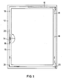
- FIG. 1 shows a tilt-and-turn sash of a window, with a frame 10, a blind or stick frame 12 and an operating handle 14.
- a tilting scissor 16 is shown with broken lines.
- a track bearing 20 is provided at the lower right corner.
- an anti-lift device 24 prevents the sash from being lifted out of the frame in the tilted state.
- the operating handle 14 is shown in full lines in a downward closed position. A horizontal position could mean the tilt position and the vertically upward position could mean the rotary position.
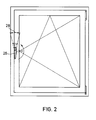
- Fig. 2 shows a schematic representation of a window sash, in which the operating handle 26 in the downward position also represents the closed position, but in the horizontal position, the rotational position.
- the tilt position is assumed in the upward position of the actuating handle.
- the arrow 28 shows an idle stroke that can be carried out with the actuating handle 26 in the tilted position.
- Fig. 3 shows a similar window sash with an operating handle .30, which from the downward The closed position can be moved into the horizontal tilt position and then into the upward rotating position. An idle stroke shown by arrow 32 of up to 90 ° is possible between the closed position and the tilted position. The empty strokes shown in FIGS. 2 and 3 are required to actuate the tilt lock.
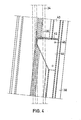
- Fig. 4 shows a first embodiment of a tilt lock with which a window or door leaf can be transferred to different defined tilt positions and locked therein.
- Fig. 4 shows a section of a stick frame 34, on which a mating claw 36 is rigidly attached.
- a section of a casement 38 is shown in a tilted position.
- a locking rod 40 is slidably guided.
- a segment 44 provided with teeth 42 is rigidly attached to this locking rod 40, for example by rivets or screws 46. The segment 44 is in engagement with the counter claw 36 between two teeth 42.
- an idle stroke of the locking bar 40 can take place, in which no other position of the wing is assumed, it is possible to lock the locking bar 40 to move a small area downward, so that the segment 44 fastened to this locking rod moves downward and comes out of the engagement position with the mating claw 36.
- the window sash can be brought into a tilting position which differs from that shown in the exemplary embodiment.
- the locking rod is pulled up again and the mating claw 36 engages between two teeth 42.
- the interlocking between the counter claw and the toothed segment has a certain self-locking, so that no independent, unintentional solution of these parts can take place.
- the parts can be made of wear-resistant material.
- the parts of the tilting lock i.e. the parts with conventional handle movements analogous to FIG. 2, in which the horizontal central position means turning the sash, the counter claw and the segment are installed.
- the central position of the handle means tilting (Fig. 3). This means that a 90 ° empty stroke to the closed position can be fully utilized.
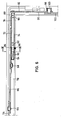
- Fig. 5 shows an embodiment of a tilt lock, in which a stepless adjustment of a tilted wing is possible.
- a tilting scissors 54 is arranged between a window sash 50 and a stick frame 52.
- the tilting scissors 54 is non-deflectable at one end via a joint 56 on the stick frame 52 / and at its other end is provided with a bolt 58 which is in an elongated hole 60 in the locking channel of the Casement 50 is guided.
- a wishbone 62 secures the position of the tilting shear 54 with the wing tilted to the maximum.
- a second wishbone 66 is rotatably attached to the tilting shear 54 via a bolt 64.
- the control arm 66 is rotatably fastened via a bolt 68 to a hollow locking rod 72 running in the sash fold 70.
- One end of a round torsion bar 74 engages in this hollow locking bar 72.
- the torsion bar 74 is rotatable in the locking bar channel by a clamp 76 78 of the wing 50 stored.
- a braking part 80 is arranged, which is held on the torsion bar 74 by a pin 82.
- a ring 84 Arranged around the torsion bar 74 is a ring 84 with a bolt 86 projecting into the wall of the closure rod channel base, which prevents longitudinal displacement of the torsion rod 74 in the closure rod channel.
- a pin 90 with a square neck is fastened via a pin 88.
- a plate 92 is riveted to this square neck.
- Fig: 6 shows a section through the casement.
- the torsion bar 74 held over the clamp 76 can be seen in the locking bar channel 78.
- the torsion bar 74 is designed as a tube and has at its left end the brake part 80 which is guided inside the hollow locking rod 72.
- the brake part 80 is covered with rubber 94. The tolerances between the rubber-coated brake part 80 and the hollow chamber of the locking rod 72 are adjusted so that the hollow locking rod 72 can be easily moved over the brake part.
- the control plate 92 riveted to the other end of the torsion bar 74 extends perpendicular to the torsion bar and is arranged to run laterally parallel to the casement.
- a curved elongated hole 96 is provided, in which a bolt 100 provided with a roller 98 is guided, which is fastened to the upper end of a locking rod 102.
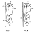
- the control plate 104 shown in FIG. 7 is intended for a tilt and turn fitting in which the central position of the actuating handle means tilting.
- the control plate 104 is attached at its upper end to the square extension 106 on the torsion bar. Above it is indicated a tilting scissors 108, a closing rod channel 109 in dash-dotted lines.
- the control plate 104 is formed with an elongated hole 110, which has approximately the shape of a boomerang. 112, 114 and 116 show possible positions of the upper end 118 of a locking rod, which is provided with a bolt and a roller.
- the lower position 112 corresponds to the closed position of the wing, position 114 to the tilt position and position 116 to the rotary position. Between the position 112 and the position 114, the brake stroke or idle stroke is carried out by the operating handle. When the end 118 is arranged in the position 112, the control plate 104 is pivoted, the torsion bar is rotated and the brake part is thus jammed in the hollow locking rod. During the actuation of the handle from the closed position to the tilting position, the control plate 104 is shifted to the right, so that the torsion bar is brought into its untwisted starting position. After the end 118 has taken the position 114, the wing can be tilted.
- the handle If the handle is now moved again in the direction of the closed position, the end 118 slides downward in the elongated hole 110, as a result of which the control plate 104 is pivoted again to the left. But this is associated with a new twisting of the torsion bar, so that the braking part is canted again braking in the hollow locking rod.
- the operating handle If another tilt position is to be taken, the operating handle must be operated again in the direction of the tilt position, after which the wing ge in the desired position is brought, whereupon the actuating handle is pivoted back into the closed position.
- the elongated hole 110 runs approximately vertically with its upper region, so that the torsion bar is not rotated.
- the control plate 120 shown in FIG. 8 is intended for a turn-tilt fitting in which the central position of the actuating handle means turning (see FIG. 2).
- an elongated hole 122 is formed in the control plate 120, which has a longer upper area.
- the end 118 of the locking rod In the closed position, the end 118 of the locking rod is in an upper position 124, for rotating the wing in an underlying rotary position 126 and for tilting in a tilted position 128.
- the actuating handle In order to lock a wing in any tilted position, the actuating handle is pivoted such that the locking rod is guided with its end 118 downward, whereby the control plate 120 is pivoted to the left, so that the torsion bar is rotated and the brake part is tilted in the hollow locking rod.
- This braking position is defined at 130 at the lower end of the elongated hole 122.
- the locking process of a wing in the tilt position is thus achieved in that the wing is brought into a tilt gap ventilation position, after which the idle stroke is actuated on the actuating handle, so that the wing is braked before closing or opening.
- the linkage, the bolt 118, the curved elongated hole 110 or 122, the control plate 104 or 120 with the torsion bar 74 and the brake part 80 are rotated by approximately 10 °, so that the brake part clamped in the cavity of the locking rod 72.
- the hollow locking rod 72 has that Strive to move over the tilting shear 54 or the wishbone 66. But this is not possible because the locking rod 72 is inhibited by the braced brake part.
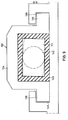
- Fig. 9 shows a first embodiment of a locking rod with the brake part guided therein.
- the locking rod 132 is U-shaped in cross section and is formed with leg ends 136 which are parallel to the center leg 134 and point outward. These leg ends 136 engage behind undercuts 138 which are provided on the closure rod channel 140.
- the locking bar 132 has a free rectangular cross section.
- a brake part 144 is fastened, which is rectangular in cross section and is provided with a rubber casing 146, which is also rectangular in cross section.
- the outer cross section of the rubber jacket 146 corresponds to the inner free cross section of the locking rod 132.
- a hollow locking bar 150 has an outer cross section that corresponds to the hollow locking bar 132.
- the inner free cross-section of the locking rod 150 consists of two semicircles, between which a rectangular central part is provided.
- An elongated brake part 154 is rigidly attached to a torsion bar 152, the end faces of which are formed in the form of circular sections, the radius of which corresponds to the radius of the semicircles of the inner cross section of the locking bar 150. If the torsion bar 152 is rotated, the brake part 154 is also rotated, which is then inside the Locking rod 150 acts as an eccentric and causes jamming between the brake part and locking rod.
- a downwardly projecting pin extension 158 Arranged on the braking part 154 is a downwardly projecting pin extension 158, which is guided in the wall of the locking rod channel 156 and prevents longitudinal displacement of the torsion rod 154 in the locking rod channel.
- the bolt boss 158 is guided in a transverse long slot 160, which allows the wobbling movement of the bolt boss.
Landscapes
- Engineering & Computer Science (AREA)
- Mechanical Engineering (AREA)
- Wing Frames And Configurations (AREA)
- Window Of Vehicle (AREA)
- Control And Other Processes For Unpacking Of Materials (AREA)
Applications Claiming Priority (2)
| Application Number | Priority Date | Filing Date | Title |
|---|---|---|---|
| DE3222678 | 1982-06-16 | ||
| DE3222678A DE3222678C2 (de) | 1982-06-16 | 1982-06-16 | Drehkippbeschlag |
Publications (2)
| Publication Number | Publication Date |
|---|---|
| EP0096744A2 true EP0096744A2 (fr) | 1983-12-28 |
| EP0096744A3 EP0096744A3 (fr) | 1985-05-22 |
Family
ID=6166217
Family Applications (1)
| Application Number | Title | Priority Date | Filing Date |
|---|---|---|---|
| EP83104444A Withdrawn EP0096744A3 (fr) | 1982-06-16 | 1983-05-05 | Ferrure pour battant oscillo-battant |
Country Status (4)
| Country | Link |
|---|---|
| US (1) | US4541200A (fr) |
| EP (1) | EP0096744A3 (fr) |
| JP (1) | JPS594772A (fr) |
| DE (1) | DE3222678C2 (fr) |
Families Citing this family (11)
| Publication number | Priority date | Publication date | Assignee | Title |
|---|---|---|---|---|
| JPH0513887Y2 (fr) * | 1986-11-20 | 1993-04-13 | ||
| FR2644504B2 (fr) * | 1988-09-26 | 1991-05-24 | Ferco Int Usine Ferrures | Ferrure pour porte, fenetre ou analogue |
| IT1235293B (it) * | 1989-06-01 | 1992-06-26 | Otlav Spa | Dispositivo per l'apertura ad anta e a ribalta di una finestra o di una porta finestra. |
| US5881498A (en) * | 1997-09-27 | 1999-03-16 | Thermo-Roll Window Corp. | Tilt and turn window lock system |
| NZ336579A (en) * | 1999-07-05 | 2001-11-30 | Interlock Group Ltd | Window closer which moves mounting hinge of window |
| DE20002467U1 (de) * | 2000-02-11 | 2000-05-04 | Gretsch-Unitas GmbH Baubeschläge, 71254 Ditzingen | Drehkippbeschlag |
| DE10113784A1 (de) * | 2001-03-21 | 2002-10-02 | Micro Mechatronic Technologies | Fenster- oder Türaufbau |
| US7325359B2 (en) * | 2004-05-28 | 2008-02-05 | Truth Hardware Corporation | Projection window operator |
| US8549789B2 (en) * | 2005-10-24 | 2013-10-08 | Andersen Corporation | Hidden window retainer system for doors |
| ITTO20060434A1 (it) * | 2006-06-15 | 2007-12-16 | Savio Spa | "gruppo di azionamento per serramenti" |
| WO2016045113A1 (fr) * | 2014-09-28 | 2016-03-31 | 李增榜 | Fenêtre suspendue à battant |
Family Cites Families (13)
| Publication number | Priority date | Publication date | Assignee | Title |
|---|---|---|---|---|
| DE1257036B (de) * | 1961-09-13 | 1967-12-21 | Otkn Puu Osakeyhtioe | Ausstellvorrichtung fuer Wende- oder Schwingfluegel von Fenstern |
| DE1977333U (de) * | 1967-11-15 | 1968-01-18 | Jaeger Frank K G | Feststellvorrichtung fuer die fluegel von fenstern, tueren od. dgl. |
| DE1708366A1 (de) * | 1967-11-15 | 1971-05-19 | Siegenia Frank Kg | Feststellvorrichtung fuer die Fluegel von Fenstern,Tueren od. dgl. |
| US3911621A (en) * | 1973-10-23 | 1975-10-14 | Extrudart Metal Products Inc | Multi-purpose window |
| DE2451556A1 (de) * | 1974-10-30 | 1976-05-06 | Siegenia Frank Kg | Feststellvorrichtung zur oeffnungsbegrenzung von kipp- und klappfluegeln, insbesondere kipp-schwenkfluegeln, an fenstern, tueren o.dgl. |
| DE2602191A1 (de) * | 1976-01-21 | 1977-07-28 | Goetz Metallbau Gmbh | Feststelleinrichtung zum festlegen des fluegels von kipp- oder kippschwingfenstern |
| DE2630720A1 (de) | 1976-07-08 | 1978-01-12 | Martin Philipp | Einrichtung, um verschluesse, insbesondere fenster und tueren in jedem beliebigen oeffnungswinkel feststellen zu koennen |
| US4074462A (en) * | 1976-12-06 | 1978-02-21 | Extrudart Metal Products, Inc. | Multi-position window |
| DE7708222U1 (de) * | 1977-03-17 | 1977-06-30 | Siegenia-Frank Kg, 5900 Siegen | Spaltlueftungsvorrichtung fuer drehfluegelfenster |
| DE2750073A1 (de) * | 1977-11-09 | 1979-05-10 | Schuermann & Co Heinz | Fenster mit einem dreh-kipp-beschlag |
| US4339892A (en) * | 1980-10-09 | 1982-07-20 | Flour City Architectural Metals | Safety window of the tilt and turn type |
| EP0051309B2 (fr) * | 1980-11-03 | 2000-12-06 | Aug. Winkhaus GmbH & Co. KG | Fenêtre |
| DE3043925C2 (de) * | 1980-11-03 | 1994-09-29 | Winkhaus Fa August | Vorrichtung an einem Fenster zur Einstellung des Flügelrahmens in eine Spaltöffnungsstellung |
-
1982
- 1982-06-16 DE DE3222678A patent/DE3222678C2/de not_active Expired
-
1983
- 1983-05-05 EP EP83104444A patent/EP0096744A3/fr not_active Withdrawn
- 1983-06-14 US US06/504,146 patent/US4541200A/en not_active Expired - Lifetime
- 1983-06-15 JP JP58108521A patent/JPS594772A/ja active Pending
Also Published As
| Publication number | Publication date |
|---|---|
| EP0096744A3 (fr) | 1985-05-22 |
| DE3222678C2 (de) | 1986-05-22 |
| DE3222678A1 (de) | 1983-12-29 |
| US4541200A (en) | 1985-09-17 |
| JPS594772A (ja) | 1984-01-11 |
Similar Documents
| Publication | Publication Date | Title |
|---|---|---|
| DE2920581C2 (de) | Zusatzverriegelung, insbesondere Mittelverriegelung, für Fenster, Türen od.dgl. | |
| DE2603240C2 (de) | Beschlag für einen kipp- und schiebbaren Flügel von Fenstern, Türen o.dgl. | |
| EP0119433B2 (fr) | Ferrure pour un panneau de fenêtre, de porte ou similaire, pouvant au moins basculer et se déplacer d'un plan dans un deuxième plan parallèle | |
| DE3041399C3 (de) | Drehkippbeschlag für Fenster od.dgl. | |
| EP0515931B2 (fr) | Ferrure pour battant oscillo-battants | |
| DE68903724T2 (de) | Beschlag fuer tuer, fenster oder dergleichen. | |
| EP0096744A2 (fr) | Ferrure pour battant oscillo-battant | |
| DE19725677C2 (de) | Fenster oder Tür an Wohnwagen, Wohnmobilen oder sonstigen Fahrzeugen, mit Verriegelungseinrichtungen mit gemeinsamer Betätigungshandhabe | |
| EP0021080B1 (fr) | Fenêtre ou porte levante, coulissante ou basculante | |
| DE2445855C2 (de) | Sperrvorrichtung an Fenstern, Türen od. dgl. mit zwei in einem Rahmen mit festem Mittelpfosten nebeneinander angeordneten, voneinander unabhängig betätigbare Treibstangenverschlüsse aufweisenden Flügeln | |
| DE2451556A1 (de) | Feststellvorrichtung zur oeffnungsbegrenzung von kipp- und klappfluegeln, insbesondere kipp-schwenkfluegeln, an fenstern, tueren o.dgl. | |
| DE3345174C2 (fr) | ||
| EP0531626B1 (fr) | Ferrure, en particulier pour des battants étant basculés et déplacés d'un plan vers un deuxième plan parallèle | |
| DE19906071C2 (de) | Drehbegrenzer für Dreh-Schiebe-Fenster | |
| DE19929818A1 (de) | Beschlag für ein Fenster oder eine Tür mit einer Spaltöffnungsstellung | |
| EP1590548B1 (fr) | Ferrure oscillobattante | |
| EP1309767B1 (fr) | Ferrure oscillo-battante pour fenetres et portes ou structures similaires | |
| DE19902579A1 (de) | Verschlußvorrichtung für den unterschlagenden Flügel zweiflügeliger setzholzloser Fenster, Türen o. dgl. | |
| DE4422213C2 (de) | Drehkippbeschlag | |
| DE1848145U (de) | Beschlag fuer dreh-kipp-fluegel von fenstern, tueren od. dgl. | |
| DE4308394A1 (de) | Beschlag für ein Fenster oder eine Tür | |
| EP0811741A2 (fr) | Ouvrant coulissant d'une porte, fenêtre ou analogue | |
| EP1582672B1 (fr) | Renvoi d'angle pour ventilation réglable et limitation d'ouverture dans une condamnation centrale | |
| DE1559736A1 (de) | An- und Abdruckvorrichtung fuer die Fluegel von Kipp-Schwenkfenstern,-tueren od.dgl. | |
| AT326521B (de) | Ausstellvorrichtung für kipp-drehflügel von fenstern, türen od.dgl. |
Legal Events
| Date | Code | Title | Description |
|---|---|---|---|
| PUAI | Public reference made under article 153(3) epc to a published international application that has entered the european phase |
Free format text: ORIGINAL CODE: 0009012 |
|
| AK | Designated contracting states |
Designated state(s): AT BE CH DE FR GB IT LI LU NL SE |
|
| 17P | Request for examination filed |
Effective date: 19841214 |
|
| PUAL | Search report despatched |
Free format text: ORIGINAL CODE: 0009013 |
|
| AK | Designated contracting states |
Designated state(s): AT BE CH DE FR GB IT LI LU NL SE |
|
| 17Q | First examination report despatched |
Effective date: 19860919 |
|
| STAA | Information on the status of an ep patent application or granted ep patent |
Free format text: STATUS: THE APPLICATION HAS BEEN WITHDRAWN |
|
| 18W | Application withdrawn |
Withdrawal date: 19880204 |
|
| RIN1 | Information on inventor provided before grant (corrected) |
Inventor name: GARTNER, FRITZ, DR. |