EP0096775B1 - Lastenpritschen, vorzugweise für den Transport von Möbeln und dergleichen - Google Patents
Lastenpritschen, vorzugweise für den Transport von Möbeln und dergleichen Download PDFInfo
- Publication number
- EP0096775B1 EP0096775B1 EP83105221A EP83105221A EP0096775B1 EP 0096775 B1 EP0096775 B1 EP 0096775B1 EP 83105221 A EP83105221 A EP 83105221A EP 83105221 A EP83105221 A EP 83105221A EP 0096775 B1 EP0096775 B1 EP 0096775B1
- Authority
- EP
- European Patent Office
- Prior art keywords
- platform
- carriage
- stage
- guide arrangement
- telescopic
- Prior art date
- Legal status (The legal status is an assumption and is not a legal conclusion. Google has not performed a legal analysis and makes no representation as to the accuracy of the status listed.)
- Expired
Links
- 238000005096 rolling process Methods 0.000 claims 1
- 238000006073 displacement reaction Methods 0.000 description 2
- 238000000034 method Methods 0.000 description 1
- 230000000284 resting effect Effects 0.000 description 1
Images


Classifications
-
- B—PERFORMING OPERATIONS; TRANSPORTING
- B66—HOISTING; LIFTING; HAULING
- B66B—ELEVATORS; ESCALATORS OR MOVING WALKWAYS
- B66B9/00—Kinds or types of lifts in, or associated with, buildings or other structures
- B66B9/16—Mobile or transportable lifts specially adapted to be shifted from one part of a building or other structure to another part or to another building or structure
Definitions
- the invention relates to a telescopic guide for a load platform of an inclined elevator for the transport of furniture with a platform truck which can be moved on the inclined elevator and which has a guide rail for the telescopic guide which can be supported in different angular positions with respect to the platform truck, with a roller guide for the method of the between the guide rail and the platform floor Load platform is provided opposite the platform truck.
- Such a telescopic guide is known for an inclined elevator mounted on a truck, the platform truck being moved on the guide rails of the inclined elevator by means of a pull rope.
- a push rod is actuated via the same pull rope, which brings a telescopic guide rail - on which the furniture platform rests - into a horizontal position.
- the furniture platform, which is supported on the guide rail, can then be partially pulled through a window opening into the interior of a building.
- the position of the platform floor between the loading position and the unloading position must be changed, i.e. the platform floor and thus the load resting on it must be tilted by approximately 90 °.
- This tilting is necessary because, due to the simple roller guide, only a small displacement of the actual load platform with respect to the guide rail is possible. For this reason, it is necessary to partially tilt the guide rail itself into the window opening via the push rod in order to extend the effective displacement path itself due to the changeable position of the guide rail (DE-OS2416938).
- the object of the invention is to eliminate this disadvantage, i. H.
- the invention solves this problem by the features of the claim.
- the load platform 1 in Fig. 2 is in its lower position. It is based on a platform truck 10 which can be moved on a telescopic or at least extendable guide 13 of an inclined elevator 12. The movability takes place in a known manner and does not affect the present invention.
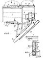
- FIG. 2 The illustration corresponding to FIG. 1 according to FIG. 2 shows that the operating side has folded down the side wall 6 on the unloading side and that the telescopic part of the load platform has been shifted to the right in the image plane.
- the original situation is shown in dash-dot lines.
- the load platform passes through a window opening 24 in the schematically illustrated wall 25 of the house.
- the upper end of the extendable guide 13 of the inclined elevator can be seen practically.
- the platform truck 10 rests with its support frame 15 on this guide and is held there against tilting in a manner not shown.
- the inclination of the platform floor 2 has already been adjusted in the loading situation via telescopic supports 30.
- the telescopic guide 7 (see also Fig. 4) is still retracted, i. H. the load platform is still in its retracted position.
- the side walls 3, 4, 5 and 6, which can be folded over hinges 26 and 27, are in the folded-up position and are connected to one another in their upper regions by locking elements, not shown.
- the side wall 6 on the unloading side is not designed over the full area and serves as a stop and grip element for pulling the load platform in the image plane to the right.
- the upper free edges 22 of the side walls 3 to 5 carry a passage-like, railing-like border, which serves on the one hand to secure the grip for the operating personnel, and on the other hand to fasten the holding straps indicated.
- the border is designed as a U-profile.
- FIG. 4 shows the double telescope guide according to section IV / IV according to FIG. 2 on an enlarged scale compared to FIG. 3.
- the double telescope guide consists of two output stages and an intermediate stage.
- the first output stage 8, which is firmly connected to the platform floor 2 consists of an angled angular profile 14.
- the second output stage 9 which is firmly connected to the support frame 15 of the platform truck 20 via support plates 29 or the telescopic supports 30 essentially U-shaped profile.
- the intermediate stage 17 is guided, which is designed approximately as a box professional 18.
- the intermediate stage 17 carries the bearings 21 for rollers 20, by means of which the individual telescopic parts can be moved relative to one another.
- the angle plate 14 of the final stage 8 passes through a slot opening 19 in the box section 18 of the intermediate stage 17 with a flange.
- the latch Bolt 11 has a housing 31 located outside the telescopic guide, which serves to accommodate a spring. With the aid of the locking bolt 11, the telescopic guides can be fixed to one another in different extended positions, in particular in one or two end positions.
Landscapes
- Engineering & Computer Science (AREA)
- Structural Engineering (AREA)
- Civil Engineering (AREA)
- Transportation (AREA)
- Automation & Control Theory (AREA)
- Types And Forms Of Lifts (AREA)
- Forklifts And Lifting Vehicles (AREA)
- Support Devices For Sliding Doors (AREA)
- Auxiliary Methods And Devices For Loading And Unloading (AREA)
Description
- Die Erfindung betrifft eine Teleskopführung für eine Lastenpritsche eines Schrägaufzuges für den Transport von Möbeln mit einem am Schrägaufzug verfahrbaren Pritschenwagen, welcher eine gegenüber dem Pritschenwagen in unterschiedlichen Winkelstellungen abstützbare Führungsschiene für die Teleskopführung aufweist, wobei zwischen der Führungsschiene und dem Pritschenboden eine Rollenführung für das Verfahren der Lastenpritsche gegenüber dem Pritschenwagen vorgesehen ist.
- Es ist eine solche Teleskopführung bei einem an einem Lastkraftwagen montierten Schrägaufzug bekannt, wobei der Pritschenwagen mittels eines Zugseiles an den Führungsschienen des Schrägaufzuges verfahren wird. Bei Erreichen eines Endanschlages am oberen Ende der Führungsschienen des Schrägaufzuges wird über das gleiche Zugseil eine Schubstange betätigt, welche eine teleskopierbare Führungsschiene - auf der die Möbelpritsche ruht-in eine horizontale Lage verbringt. Die an der Führungsschiene rollend abgestützte Möbelpritsche kann nachfolgend teilweise durch eine Fensteröffnung in das Innere eines Gebäudes gezogen werden.
- Bei der bekannten Vorrichtung muss die Lage des Pritschenbodens zwischen der Beladeposition und der Entladeposition verändert werden, d.h. der Pritschenboden und damit die auf ihm ruhende Last müssen um etwa 90° gekippt werden. Dieses Kippen ist erforderlich, weil aufgrund der einfachen Rollenführung nur ein geringer Verschiebeweg der eigentlichen Lastenpritsche gegenüber der Führungsschiene möglich ist. Aus diesem Grunde ist es erforderlich, die Führungsschiene selbst über die Schubstange teilweise in die Fensteröffnung hinein zu kippen, um den wirksamen Verschiebeweg durch die veränderbare Lage der Führungsschiene selbst zu verlängern (DE-OS2416938).
- Aufgabe der Erfindung ist es, diesen Nachteil zu beseitigen, d. h. eine Teleskopführung für eine Lastenpritsche, insbesondere für den Transport von Möbeln so auszubilden, dass die Lage ihrer Ladefläche in horizontaler Richtung gesehen veränderbar ist, d.h. dass beispielsweise die Ladefläche von einer Position ausserhalb einer Fensteröffnung in eine Position innerhalb einer Fensteröffnung verbringbar ist.
- Die Erfindung löst die gestellte Aufgabe durch die Merkmale des Patentanspruches.
- Die Erfindung wird nachfolgend anhand eines Ausführungsbeispieles näher erläutert.
- Es zeigen:
- Fig. 1 die Ansicht eines Schrägaufzuges mit schematisch dargestellter Seitenwand eines Gebäudes, wobei sich die Lastenpritsche in ihrer unteren Ladesituation befindet,
- Fig. 2 eine Darstellung entsprechend Fig. 1, wobei sich die Lastenpritsche in ihrer oberen Entladeposition befindet,
- Fig. 3 eine perspektivische Darstellung der tefeskopierbaren Lastenpritsche sowie
- Fig.4 den Schnitt IV/IV nach Fig. durch die Teleskopführung.
- In den einzelnen Figuren wurden gleiche Bauteile mit gleichen Bezugszeichen bezeichnet.
- Die Lastenpritsche 1 in Fig. 2 befindet sich in ihrer unteren Position. Sie stützt sich auf einen Pritschenwagen 10 ab, der an einer teleskopierbaren oder zumindest verlängerbaren Führung 13 eines Schrägaufzuges 12 verfahrbar ist. Die Verfahrbarkeit vollzieht sich in bekannter Weise und berührt nicht die hier vorliegende Erfindung.
- Die der Fig. 1 entsprechende Darstellung nach Fig. 2 lässt erkennen, dass durch das Bedienungspersonal die entladeseitige Seitenwand 6 herabgeklappt und der teleskopierbare Teil der Lastenpritsche in der Bildebene nach rechts verschoben worden ist. Die Ursprungssituation ist strichpunktiert dargestellt. Die Lastenpritsche durchfährt dabei in dem aufgezeigten Ausführungsbeispiel eine Fensteröffnung 24 in der schematisch dargestellten Wand 25 des Hauses.
- Aus der Fig. 3 ist praktisch das obere Ende der verlängerbaren Führung 13 des Schrägaufzuges erkennbar; der Pritschenwagen 10 ruht mit seinem Tragrahmen 15 auf dieser Führung und ist dort in nicht näher dargestellter Weise kippsicher gehalten. Der Pritschenboden 2 ist in seiner Neigung über Teleskopstützen 30 bereits in der Beladesituation eingestellt worden. Die Teleskopführung 7 (siehe auch Fig. 4) ist noch eingefahren, d. h. die Lastenpritsche befindet sich noch in ihrer eingefahrenen Position. Die Seitenwände 3, 4, 5 und 6, die über Scharniere 26 bzw. 27 klappbar sind, befinden sich in hochgeklappter Position und sind in ihren oberen Bereichen über nicht dargestellte Riegelelemente miteinander verbunden. Die entladeseitige Seitenwand 6 ist nicht vollflächig ausgebildet und dient als Anschlag- und Griffelement zum Vorziehen der Lastenpritsche in der Bildebene nach rechts. Die oberen freien Kanten 22 der Seitenwände 3 bis 5 tragen eine Durchlässe freilassende, geländerartige Umrandung, die zum einen als Griffsicherung für das Bedienungspersonal, zum anderen der Befestigung von andeutungsweise dargestellten Haltegurten dient. Die Umrandung ist als U-Profil ausgebildet.
- In der Fig. 4 ist die Doppelteleskopführung gemäss Schnitt IV/IV nach Fig. 2 in einem gegenüber der Fig. 3 vergrösserten Massstab dargestellt. Die Doppelteleskopführung besteht aus zwei Endstufen und einer Zwischenstufe. Die erste Endstufe 8, die mit dem Pritschenboden 2 fest verbunden ist, besteht aus einem gegensinnig abgekröpften Winkelprofil 14. Die zweite Endstufe 9, die über Stützbleche 29 bzw. über die Teleskopstützen 30 fest mit dem Tragrahmen 15 des Pritschenwagens 20 verbunden ist, weist ein im wesentlichen U-förmiges Profil auf. Zwischen diesen beiden Endstufen ist die Zwischenstufe 17 geführt, die in etwa als Kastenprofii 18 ausgebildet ist. Die Zwischenstufe 17 trägt die Lager 21 für Rollen 20, mit deren Hilfe die einzelnen Teleskopteile zueinander bewegbar sind. Das Winkelblech 14 der Endstufe 8 durchgreift mit einem Flansch eine Schlitzöffnung 19 im Kastenprofil 18 der Zwischenstufe 17. Der Riegelbolzen 11 weist ein ausserhalb der Teleskopführung liegendes Gehäuse 31, welches der Aufnahme einer Feder dient, auf. Mit Hilfe des Riegelbolzens 11 sind die Teleskopführungen zueinander in unterschiedlichen Ausfahrstellungen, insbesondere in ein bzw. zwei Endstellungen festlegbar.

Claims (1)
- Teleskopführung für eine Lastenpritsche eines Schrägaufzuges für den Transport von Möbeln mit einem am Schrägaufzug verfahrbaren Pritschenwagen, welcher eine gegenüber dem Pritschenwagen in unterschiedlichen Winkelstellungen abstützbare Führungsschiene für die Teleskopführung aufweist, wobei zwischen der Führungsschiene und dem Pritschenboden eine Rollenführung für das Verfahren der Lastenpritsche gegenüber dem Pritschenwagen vorgesehen ist, gekennzeichnet durch folgende Merkmale:a) die Lage des Pritschenbodens (2) und der ihm zugeordneten Teleskopführung (7) ist mit Bezug auf die Beladeposition und die Entladeposition gleich;b) die Teleskopführung (7) weist eine unterseitig des Pritschenbodens (2) angeordnete erste Endstufe (8), eine am Tragrahmen (15) des Pritschenwagens (10) angeordnete zweite Endstufe (9) und eine zwischen den beiden Endstufen (8, 9) rollend [Rollen (20)] geführte Zwischenstufe (17) auf;c) die unterseitig des Pritschenbodens (2) angeordnete erste Endstufe (8) ist durch ein gegensinnig abgekröpftes Winkelblech (14) gebildet;d) die am Tragrahmen (15) des Pritschenwagens (10) angeordnete zweite Endstufe (9) ist durch ein im wesentlichen U-förmig ausgebildetes Winkelblech (16) gebildet;e) die zwischen den beiden Endstufen (8, 9) geführte Zwischenstufe (17) weist ein Kastenprofil (18) mit einer Schlitzöffnung (19) für den Durchgriff der unterseitig des Pritschenbodens (2) angeordneten ersten Endstufe (8) auf;f) die Rollen (20) der an den Endstufen (8, 9) geführten Zwischenstufe (17) sind beidseitig in den gegenüberliegenden Wänden des Kastenprofils (18) der Zwischenstufe (17) gelagert.
Priority Applications (1)
| Application Number | Priority Date | Filing Date | Title |
|---|---|---|---|
| AT83105221T ATE26249T1 (de) | 1982-06-16 | 1983-05-26 | Lastenpritschen, vorzugweise fuer den transport von moebeln und dergleichen. |
Applications Claiming Priority (2)
| Application Number | Priority Date | Filing Date | Title |
|---|---|---|---|
| DE3222509A DE3222509C2 (de) | 1982-06-16 | 1982-06-16 | Teleskopführung für eine Lastenpritsche eines Schrägaufzuges für den Transport von Möbeln |
| DE3222509 | 1982-06-16 |
Publications (3)
| Publication Number | Publication Date |
|---|---|
| EP0096775A2 EP0096775A2 (de) | 1983-12-28 |
| EP0096775A3 EP0096775A3 (en) | 1985-01-09 |
| EP0096775B1 true EP0096775B1 (de) | 1987-04-01 |
Family
ID=6166122
Family Applications (1)
| Application Number | Title | Priority Date | Filing Date |
|---|---|---|---|
| EP83105221A Expired EP0096775B1 (de) | 1982-06-16 | 1983-05-26 | Lastenpritschen, vorzugweise für den Transport von Möbeln und dergleichen |
Country Status (5)
| Country | Link |
|---|---|
| US (1) | US4546854A (de) |
| EP (1) | EP0096775B1 (de) |
| JP (1) | JPS5948378A (de) |
| AT (1) | ATE26249T1 (de) |
| DE (2) | DE3222509C2 (de) |
Families Citing this family (35)
| Publication number | Priority date | Publication date | Assignee | Title |
|---|---|---|---|---|
| IT1183935B (it) * | 1985-09-02 | 1987-10-22 | Francesco Bono | Montacarichi autotrasportabile con braccio telescopico binato |
| DE8528810U1 (de) * | 1985-10-10 | 1985-11-21 | Albert Böcker GmbH & Co KG, 4712 Werne | Lastenpritsche für Schrägaufzüge |
| JPS63300100A (ja) * | 1987-05-29 | 1988-12-07 | 株式会社 関電工 | 重量物運搬装置 |
| US4793437A (en) * | 1987-07-20 | 1988-12-27 | Philip Hanthorn | Portable lift with telescopic booms and load-carrying apparatus |
| US4875547A (en) * | 1987-07-20 | 1989-10-24 | Hanthorn Philip T | Portable conveyor system with telescopic boom assembly and load carrying apparatus |
| US4930599A (en) * | 1989-08-17 | 1990-06-05 | Simms Sr Ernest L | Ladder and carriage combination |
| FR2667582B1 (fr) * | 1990-10-04 | 1995-06-30 | Cgti | Dispositif pour le levage et l'installation d'un materiel au sommet d'un ouvrage de grande hauteur. |
| AU1087992A (en) * | 1991-05-10 | 1992-06-25 | Redara Pty Ltd | Bungy jumping tower |
| EP0536846A2 (de) * | 1991-10-10 | 1993-04-14 | Nv Nuyts Orb | Kraftfahrzeugkombination von Umzugsfahrzeug und Leiteraufzug |
| DE9202227U1 (de) * | 1992-02-21 | 1993-04-15 | Teupen Maschinenbaugesellschaft mbH, 4432 Gronau | Mobiles Arbeitsgerät, insbesondere Hubarbeitsbühne |
| JP2573873Y2 (ja) * | 1993-05-17 | 1998-06-04 | 日本通運株式会社 | 荷揚げリフトの荷台 |
| USD392056S (en) | 1997-04-30 | 1998-03-10 | Lung-Chou Wang | Guide rail Device |
| DE19808503C2 (de) * | 1998-02-13 | 2003-06-18 | Hoetker Metallbau Dirk Hoetker | Montagevorrichtung für den Ein- und Ausbau von Markisen |
| FR2797905B1 (fr) * | 1999-08-24 | 2001-09-28 | Jean Pierre Bererd | Dispositif destine au levage d'elements de construction ayant une forme generale de panneaux |
| US6527088B1 (en) | 2000-12-27 | 2003-03-04 | David W. Fowler | Lift apparatus for transporting packages between two or more floors of a building |
| US6857508B2 (en) * | 2002-10-31 | 2005-02-22 | Inventio Ag | Elevator hoist machine installation apparatus |
| US8316994B1 (en) * | 2008-02-01 | 2012-11-27 | Elevated Technologies Llc | Battery powered vertical lift assembly |
| US8002512B1 (en) * | 2009-01-29 | 2011-08-23 | Blehm Berle G | Material transport |
| US20100225133A1 (en) * | 2009-03-06 | 2010-09-09 | Mark Ferrara | Hoisting system for rescue operations |
| US9156657B2 (en) * | 2009-09-11 | 2015-10-13 | William J. Sturmer | Lift and hold device |
| DE102011052497A1 (de) * | 2010-10-13 | 2012-04-19 | Detlef Henry Friedrich | Schienentransportsystem für die Beladung und Entladung der Kombüse eines Flugzeuges |
| ES2469765B1 (es) * | 2012-12-17 | 2015-03-31 | Antonio Jesús RUIZ ESPAÑA | Dispositivo transportador de carga |
| CN103407865A (zh) * | 2013-08-12 | 2013-11-27 | 山东德嘉石油装备有限公司 | 一种斜式人货两用升降机 |
| CA2826315A1 (en) * | 2013-09-06 | 2015-03-06 | Mattawa Industrial Services Inc. | Elevation conveyance system and method |
| KR101618615B1 (ko) | 2013-11-14 | 2016-05-09 | 삼성중공업 주식회사 | 위험물 배출 장치 |
| US20150300090A1 (en) * | 2014-04-21 | 2015-10-22 | Warren STRAND | Ladder lift system |
| JP6412373B2 (ja) * | 2014-09-04 | 2018-10-24 | 株式会社三共 | リフト車 |
| US9944495B2 (en) * | 2015-10-19 | 2018-04-17 | Gray Andrew Webber | Portable lift |
| CN105197723B (zh) * | 2015-10-27 | 2017-06-27 | 中国矿业大学 | 一种变坡度斜向提升容器试验平台及方法 |
| CN105858410B (zh) * | 2016-06-22 | 2018-02-09 | 中国矿业大学 | 一种变坡度斜向运行容器倾角自动调节装置及方法 |
| CN108222478B (zh) * | 2016-06-28 | 2020-04-28 | 海门市知舟工业设计有限公司 | 一种可定向转换的建筑支撑辅助设备 |
| CN106108772B (zh) * | 2016-06-28 | 2018-07-27 | 柯曾国 | 一种建筑玻璃清洁用旋转支撑设备 |
| CN108125608B (zh) * | 2016-06-28 | 2020-07-24 | 马建军 | 一种基于并联机构的高层建筑擦窗支撑作业智能机器人 |
| RU191905U1 (ru) * | 2019-01-30 | 2019-08-28 | Наталья Евгеньевна Баринова | Бытовой антресольный подъемник |
| US11572253B2 (en) | 2019-03-15 | 2023-02-07 | John Sund | Incline elevator and modular deck system and methods for the assembly, use and shipping thereof |
Family Cites Families (19)
| Publication number | Priority date | Publication date | Assignee | Title |
|---|---|---|---|---|
| DE20902C (de) * | 1900-01-01 | R. G. BROWN in | Verfahren und Vorrichtung zur Regulirung der Geschwindigkeit von Schiffsmaschinen durch Elektrizität | |
| US2787278A (en) * | 1952-12-30 | 1957-04-02 | Mitchell Mainternance Company | Apparatus for over-head service work |
| CH322579A (de) * | 1954-04-21 | 1957-06-30 | Merz Meyer Alice | Doppelauszugeinrichtung für Schubladen |
| US2926048A (en) * | 1956-12-31 | 1960-02-23 | Phillips Petroleum Co | Bearing |
| GB943974A (en) * | 1961-07-22 | 1963-12-11 | Leonard Evans | A mobile lift |
| DE1892158U (de) * | 1963-02-01 | 1964-04-30 | Maschf Augsburg Nuernberg Ag | Stapelgeraet fuer magazinanlagen. |
| DE1429560A1 (de) * | 1963-09-14 | 1969-01-02 | Jul Haedrich & Co | Doppelauszugeinrichtung fuer Schubladen |
| US3344885A (en) * | 1966-05-02 | 1967-10-03 | Edgar E Rasmussen | Personnel lift |
| US3478904A (en) * | 1967-05-17 | 1969-11-18 | Boeing Co | Cargo loading mechanism |
| DE1810956A1 (de) * | 1968-11-26 | 1970-05-27 | Demag Zug Gmbh | Hublader fuer Regalbedienung |
| CH474975A (de) * | 1969-01-10 | 1969-07-15 | Buob Beat | Ausziehvorrichtung für Schubladen |
| FR2038496A5 (de) * | 1969-03-20 | 1971-01-08 | Bron Jean | |
| US3848937A (en) * | 1972-04-26 | 1974-11-19 | Coach & Car Equip Corp | Slide mechanism |
| GB1359410A (en) * | 1972-12-15 | 1974-07-10 | Bromsregulator Svenska Ab | Slack-adjusters |
| DE2416938A1 (de) * | 1974-04-08 | 1975-10-16 | Albert Boecker Fa | Absetzbarer lastenaufzug oder leiter ueber dem laderaum von lastkraftwagen montiert |
| IT7621014U1 (it) * | 1976-03-22 | 1977-09-22 | Susta Spa | Guida telescopica per cassetti, in particolare cassetti metallici. |
| US4043687A (en) * | 1976-04-12 | 1977-08-23 | The United States Of America As Represented By The Secretary Of The Army | Latched telescoping members |
| DE2924543C2 (de) * | 1979-06-19 | 1981-08-20 | Dechentreiter Maschinenbau KG, 8854 Asbach-Bäumenheim | Leiteraufzug, insbesondere für Möbeltransporte |
| DE3020791C2 (de) * | 1980-05-31 | 1982-11-25 | psb GmbH Förderanlagen und Lagertechnik, 6780 Pirmasens | Regalbediengerät für Hochregallager |
-
1982
- 1982-06-16 DE DE3222509A patent/DE3222509C2/de not_active Expired
-
1983
- 1983-05-26 DE DE8383105221T patent/DE3370612D1/de not_active Expired
- 1983-05-26 AT AT83105221T patent/ATE26249T1/de not_active IP Right Cessation
- 1983-05-26 EP EP83105221A patent/EP0096775B1/de not_active Expired
- 1983-06-10 US US06/503,289 patent/US4546854A/en not_active Expired - Fee Related
- 1983-06-16 JP JP58106857A patent/JPS5948378A/ja active Pending
Also Published As
| Publication number | Publication date |
|---|---|
| US4546854A (en) | 1985-10-15 |
| DE3370612D1 (en) | 1987-05-07 |
| EP0096775A2 (de) | 1983-12-28 |
| EP0096775A3 (en) | 1985-01-09 |
| JPS5948378A (ja) | 1984-03-19 |
| ATE26249T1 (de) | 1987-04-15 |
| DE3222509A1 (de) | 1983-12-22 |
| DE3222509C2 (de) | 1987-02-05 |
Similar Documents
| Publication | Publication Date | Title |
|---|---|---|
| EP0096775B1 (de) | Lastenpritschen, vorzugweise für den Transport von Möbeln und dergleichen | |
| EP0096776B1 (de) | Schrägaufzug zur Beförderung von Lasten | |
| DE69002122T2 (de) | Autonome Frachtlade- und Frachtausladevorrichtung, die in einem Flugzeug integriert ist. | |
| DE19519109A1 (de) | Transportvorrichtung | |
| DE10204892B4 (de) | Fördereinrichtung für den Vertikaltransport von Verpflegungsbehältnissen in Verkehrsflugzeugen | |
| DE19955801B4 (de) | Transportvorrichtung zum Befördern von Lasten in vertikaler Richtung zwischen horizontalen Ebenen | |
| DE69800024T2 (de) | Treppenlift | |
| DE4429927A1 (de) | Container | |
| DE4403658A1 (de) | Transportwagen, insbesondere Rollbehälter, aus einem mit Lenkrollen bestückten Fahrgestell und einem Aufbau | |
| DE3248083A1 (de) | Hebetuer | |
| DE19606196A1 (de) | Be- und Entladevorrichtung | |
| EP0679788A1 (de) | Laufwerk sowie Schiene und Verschiebeeinrichtung | |
| DE102019134494B4 (de) | Mobiler umbauter Raum | |
| AT407367B (de) | Untere ausstellvorrichtung für eine schiebewand | |
| DE3046178A1 (de) | "aufbau eines lastkraftwagens oder anhaengers" | |
| DE19822633A1 (de) | Arbeitsbühne mit einem durch ein Scherenhubwerk höhenverstellbaren Arbeitsboden | |
| DE68902225T2 (de) | Fahrzeug mit verschiebbaren seitenschliesselementen. | |
| EP0510528A2 (de) | Aufzug für Baumaterialien, Gerüstelemente und Gerüstmontagen | |
| DE8217271U1 (de) | Lastenpritsche, vorzugsweise für den Transport von Möbeln u. dgl. | |
| DE2703713A1 (de) | Parkeinrichtung fuer kraftfahrzeuge | |
| DE7128036U (de) | Hebebühne | |
| DE3816156A1 (de) | Beladevorrichtung fuer den schlitten eines schraegaufzuges | |
| DE959759C (de) | Skip-Schraegschachtfoerderung | |
| DE19643797C1 (de) | Vorrichtung zum Unterteilen des Laderaumes einer Transporteinheit | |
| DE8217270U1 (de) | Schrägaufzug zur Förderung von Lasten |
Legal Events
| Date | Code | Title | Description |
|---|---|---|---|
| PUAI | Public reference made under article 153(3) epc to a published international application that has entered the european phase |
Free format text: ORIGINAL CODE: 0009012 |
|
| AK | Designated contracting states |
Designated state(s): AT BE CH DE FR GB IT LI LU NL SE |
|
| 17P | Request for examination filed |
Effective date: 19840419 |
|
| PUAL | Search report despatched |
Free format text: ORIGINAL CODE: 0009013 |
|
| AK | Designated contracting states |
Designated state(s): AT BE CH DE FR GB IT LI LU NL SE |
|
| ITF | It: translation for a ep patent filed | ||
| GRAA | (expected) grant |
Free format text: ORIGINAL CODE: 0009210 |
|
| AK | Designated contracting states |
Kind code of ref document: B1 Designated state(s): AT BE CH DE FR GB IT LI LU NL SE |
|
| REF | Corresponds to: |
Ref document number: 26249 Country of ref document: AT Date of ref document: 19870415 Kind code of ref document: T |
|
| REF | Corresponds to: |
Ref document number: 3370612 Country of ref document: DE Date of ref document: 19870507 |
|
| ET | Fr: translation filed | ||
| PLBE | No opposition filed within time limit |
Free format text: ORIGINAL CODE: 0009261 |
|
| STAA | Information on the status of an ep patent application or granted ep patent |
Free format text: STATUS: NO OPPOSITION FILED WITHIN TIME LIMIT |
|
| 26N | No opposition filed | ||
| PGFP | Annual fee paid to national office [announced via postgrant information from national office to epo] |
Ref country code: FR Payment date: 19920330 Year of fee payment: 10 |
|
| PGFP | Annual fee paid to national office [announced via postgrant information from national office to epo] |
Ref country code: DE Payment date: 19920407 Year of fee payment: 10 |
|
| PGFP | Annual fee paid to national office [announced via postgrant information from national office to epo] |
Ref country code: LU Payment date: 19920506 Year of fee payment: 10 |
|
| PGFP | Annual fee paid to national office [announced via postgrant information from national office to epo] |
Ref country code: GB Payment date: 19920508 Year of fee payment: 10 |
|
| PGFP | Annual fee paid to national office [announced via postgrant information from national office to epo] |
Ref country code: SE Payment date: 19920518 Year of fee payment: 10 |
|
| PGFP | Annual fee paid to national office [announced via postgrant information from national office to epo] |
Ref country code: BE Payment date: 19920520 Year of fee payment: 10 |
|
| PGFP | Annual fee paid to national office [announced via postgrant information from national office to epo] |
Ref country code: AT Payment date: 19920521 Year of fee payment: 10 |
|
| ITTA | It: last paid annual fee | ||
| PGFP | Annual fee paid to national office [announced via postgrant information from national office to epo] |
Ref country code: NL Payment date: 19920531 Year of fee payment: 10 |
|
| PGFP | Annual fee paid to national office [announced via postgrant information from national office to epo] |
Ref country code: CH Payment date: 19920820 Year of fee payment: 10 |
|
| EPTA | Lu: last paid annual fee | ||
| PG25 | Lapsed in a contracting state [announced via postgrant information from national office to epo] |
Ref country code: LU Free format text: LAPSE BECAUSE OF NON-PAYMENT OF DUE FEES Effective date: 19930526 Ref country code: GB Effective date: 19930526 Ref country code: AT Effective date: 19930526 |
|
| PG25 | Lapsed in a contracting state [announced via postgrant information from national office to epo] |
Ref country code: SE Effective date: 19930527 |
|
| PG25 | Lapsed in a contracting state [announced via postgrant information from national office to epo] |
Ref country code: LI Effective date: 19930531 Ref country code: CH Effective date: 19930531 Ref country code: BE Effective date: 19930531 |
|
| BERE | Be: lapsed |
Owner name: ALBERT BOCKER G.M.B.H. & CO. K.G. Effective date: 19930531 |
|
| PG25 | Lapsed in a contracting state [announced via postgrant information from national office to epo] |
Ref country code: NL Effective date: 19931201 |
|
| NLV4 | Nl: lapsed or anulled due to non-payment of the annual fee | ||
| GBPC | Gb: european patent ceased through non-payment of renewal fee |
Effective date: 19930526 |
|
| PG25 | Lapsed in a contracting state [announced via postgrant information from national office to epo] |
Ref country code: FR Effective date: 19940131 |
|
| REG | Reference to a national code |
Ref country code: CH Ref legal event code: PL |
|
| PG25 | Lapsed in a contracting state [announced via postgrant information from national office to epo] |
Ref country code: DE Effective date: 19940201 |
|
| REG | Reference to a national code |
Ref country code: FR Ref legal event code: ST |
|
| EUG | Se: european patent has lapsed |
Ref document number: 83105221.2 Effective date: 19931210 |