EP0096776A2 - Ascenseur incliné pour le transport de charges - Google Patents
Ascenseur incliné pour le transport de charges Download PDFInfo
- Publication number
- EP0096776A2 EP0096776A2 EP83105222A EP83105222A EP0096776A2 EP 0096776 A2 EP0096776 A2 EP 0096776A2 EP 83105222 A EP83105222 A EP 83105222A EP 83105222 A EP83105222 A EP 83105222A EP 0096776 A2 EP0096776 A2 EP 0096776A2
- Authority
- EP
- European Patent Office
- Prior art keywords
- elevator
- rocker
- guide rail
- platform
- platform truck
- Prior art date
- Legal status (The legal status is an assumption and is not a legal conclusion. Google has not performed a legal analysis and makes no representation as to the accuracy of the status listed.)
- Granted
Links
Images

Classifications
-
- B—PERFORMING OPERATIONS; TRANSPORTING
- B66—HOISTING; LIFTING; HAULING
- B66B—ELEVATORS; ESCALATORS OR MOVING WALKWAYS
- B66B9/00—Kinds or types of lifts in, or associated with, buildings or other structures
- B66B9/16—Mobile or transportable lifts specially adapted to be shifted from one part of a building or other structure to another part or to another building or structure
-
- Y—GENERAL TAGGING OF NEW TECHNOLOGICAL DEVELOPMENTS; GENERAL TAGGING OF CROSS-SECTIONAL TECHNOLOGIES SPANNING OVER SEVERAL SECTIONS OF THE IPC; TECHNICAL SUBJECTS COVERED BY FORMER USPC CROSS-REFERENCE ART COLLECTIONS [XRACs] AND DIGESTS
- Y10—TECHNICAL SUBJECTS COVERED BY FORMER USPC
- Y10S—TECHNICAL SUBJECTS COVERED BY FORMER USPC CROSS-REFERENCE ART COLLECTIONS [XRACs] AND DIGESTS
- Y10S187/00—Elevator, industrial lift truck, or stationary lift for vehicle
- Y10S187/90—Temporary construction elevator for building
Definitions
- the invention relates to an inclined elevator for the transport of loads by means of a load platform which is guided on the guide rails of the inclined elevator and has a cable-pull platform truck carrying the load platform.
- Such inclined elevators with cable-pull platform trucks are known, which are used to transport a wide variety of goods.
- building accessories are transported with such inclined elevators.
- the platform trucks of the cargo platforms run on diagonally upward-facing guide rails; There is a difficulty in the area of the removal stations in moving the cargo as far as possible into an accessible removal area transport. In other words; the load arriving at the end of an inclined straight guideway of a freight elevator is difficult for the operating personnel to reach.
- the previously known design of the platform truck does not allow - in the area of the removal position of the platform truck - a method of the platform truck in a relatively simple manner in the direction of the removal area - and here mainly a horizontally directed method is addressed.
- the object of the invention is therefore to develop the inclined elevator of the type mentioned in such a way that the removal of the load is facilitated by the platform truck can be brought into a more favorable unloading position at the upper end of the inclined elevator without any significant structural effort.
- the invention solves the problem in an inclined elevator for the transport of loads by means of a load platform which is guided in a rolling manner on guide rails of the inclined elevator with a rope-pulled platform truck carrying the load platform in that the platform truck is guided on the guide rail via rollers which are displaced on rockers.
- This particular shifting of the rollers on the swingarms enables the platform of the platform truck to be adapted to a course of the guide rails that deviates from the oblique straight line.
- the invention is implemented in detail so that the platform truck has a front support axis and a rear support axis and each support axis is provided at its free ends with a rocker carrying the rollers.
- the roller arrangement is advantageously made such that the rocker is pivotally displaced on the support frame of the platform truck in such a way that its pivot axis lies between two upper rollers arranged in the direction of the elevator. This arrangement ensures that the upper rollers reliably transfer the load when driving over kinked joints.
- the free end of the support axis simultaneously forms the pivot axis for the rocker.
- the rockers lying one behind the other in the elevator direction have different roller configurations.
- This roller assembly is designed according to a further feature so that the rocker located at the front in the elevator direction has two upper rollers resting on the guide rail and two lower rollers engaging under the guide rail, such that the axes of the lower rollers between the Axes of the top rollers lie. The design ensures that the kink is reliably run over, ie the front lower roller is already engaged in the bent part of the guide rail and secures the load against lifting, while the rear lower roller is still in the area of the inclined upward guidance of the inclined elevator.
- the rear rocker in the direction of the elevator has two upper rollers resting on the guide rail and one lower roller in the elevator direction behind the pivot axis of the rocker, but in front of the axis of the rear upper roller, which engages under the guide rail.
- This last-mentioned lower roller is sufficient to secure the rear part of the platform truck against lifting off.
- a particular advantage of the invention is seen in the fact that the pivot axis of the rocker simultaneously forms the pivot axis for a cable-dependent brake, in particular for an eccentric brake.
- the support axis of the platform truck, the pivot axis of the rocker and the pivot axis of the eccentric brake can be arranged coaxially to one another.
- a fastening stop for a cable pull is provided on at least one support axle of the platform truck, which also serves to unlock the spring-loaded eccentric brake.
- the eccentric brakes can be arranged on the free ends of both axes. In this case, the eccentric that rests on the upper side of the guide rail in the operating state is associated with a brake pad that rests on the underside of the guide rail and is arranged on the rocker.
- the configuration and arrangement of the rockers according to the invention fundamentally facilitates the guidance of the platform truck on the guide rails and contributes to the uniformity of the surface pressure
- the teaching of the invention is particularly advantageous in the case of kinked or curved guide rails of the inclined elevator.
- the guide rails of the inclined elevator are designed to be kinked in the unloading position of the platform truck, the kinked guide rails being of such a length that the platform truck is in its unloading position with the front rocker in the elevator direction on the preferably horizontally running bent part of the guide rail and with its rear rocker in the elevator direction on the obliquely upward extending part of the guide rail.
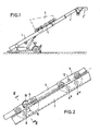
- the inclined lift is designated by 1 and the load platform located on the platform truck 4 by 3 in an overall view. It can be seen that the load platform, which is located halfway up the telescopic inclined elevator, has a certain inclined position. This inclined position is canceled when the front rocker 5 (see also FIG. 6) the bent part 2 'of the Runs over guide rail 2.
- the platform truck 4 essentially consists of the supporting frame 11, two supporting axes 9 and 10 connecting the supporting frames 11 to one another and the associated rockers 5 and 6.
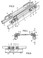
- the rockers 5 and 6 are mounted on the supporting axes 9 and 10 in the embodiment shown, i.e. the pivot axis of the rocker 5 or 6 is aligned with the axes 9 and 10.
- the pivot axis 12 of the rocker 5 or 6 is arranged offset to the support axes 9 and 10 on the support frame 11.
- the front rocker 5 in the direction of the elevator (arrow 21 in FIG. 6) has two upper rollers 7 "and 7" 'with which it guides on the guide rail 2.
- it has two lower rollers 8 "and 8"' (see 6), which are arranged such that their axes 13 and 13 'lie between the axes 14 and 14' of the top rollers 7 "and 7" ".
- FIG. 6 it is ensured that when the guide rail 2 or 2 'is bent over at 20', the front lower roller 8 "'already secures against lifting, while the rear lower roller 8" is still in the region of the obliquely upwardly extending guide rail 2. This naturally applies in reverse order to the method of the platform truck in the opposite direction.
- the rear swing arm 6 also has two top rollers 7 and 7 '; however, only one lower roller 8; a further lower roller is not required because the rocker 6 is substantially relieved of pressure when viewed from below, so that the single lower roller only has a safety function against lifting off.
- the eccentric 18 with an eccentric brake 15 is displaced on the outside in the area of the rocker above the guide rail.
- the eccentric brake 15 is released by the cable 17 engaging the stop 16. Only when the cable 17 is completely relieved does the spring-loaded eccentric brake 15 ensure that the eccentric is pivoted into the braking position shown in FIG. 5.
- the horizontal guide flange 23 of the guide rails 2, 2 ' is frictionally clamped between the eccentric 18 and a brake pad 19.
- an adjustment device can be provided in a known manner between the load platform 3 and the platform truck, with the aid of which the load platform can be pivoted relative to the platform truck.
- the rocker according to the invention in connection with the possibility of driving over the kink shown at 20, it may, however, be expedient to dispense with such an additional possibility of adjustment, since the load platform is automatically brought into a horizontal position after the kink has been appropriately passed over, at the same time it is moved sufficiently far horizontally into the removal or unloading area.
Landscapes
- Engineering & Computer Science (AREA)
- Structural Engineering (AREA)
- Civil Engineering (AREA)
- Transportation (AREA)
- Automation & Control Theory (AREA)
- Types And Forms Of Lifts (AREA)
- Lift-Guide Devices, And Elevator Ropes And Cables (AREA)
- Valve-Gear Or Valve Arrangements (AREA)
- Forklifts And Lifting Vehicles (AREA)
Priority Applications (1)
| Application Number | Priority Date | Filing Date | Title |
|---|---|---|---|
| AT83105222T ATE26250T1 (de) | 1982-06-16 | 1983-05-26 | Schraegaufzug zur befoerderung von lasten. |
Applications Claiming Priority (2)
| Application Number | Priority Date | Filing Date | Title |
|---|---|---|---|
| DE3222508A DE3222508C2 (de) | 1982-06-16 | 1982-06-16 | Schrägaufzug zur Förderung von Lasten |
| DE3222508 | 1982-06-16 |
Publications (3)
| Publication Number | Publication Date |
|---|---|
| EP0096776A2 true EP0096776A2 (fr) | 1983-12-28 |
| EP0096776A3 EP0096776A3 (en) | 1985-01-09 |
| EP0096776B1 EP0096776B1 (fr) | 1987-04-01 |
Family
ID=6166121
Family Applications (1)
| Application Number | Title | Priority Date | Filing Date |
|---|---|---|---|
| EP83105222A Expired EP0096776B1 (fr) | 1982-06-16 | 1983-05-26 | Ascenseur incliné pour le transport de charges |
Country Status (5)
| Country | Link |
|---|---|
| US (1) | US4550806A (fr) |
| EP (1) | EP0096776B1 (fr) |
| JP (1) | JPS5948377A (fr) |
| AT (1) | ATE26250T1 (fr) |
| DE (2) | DE3222508C2 (fr) |
Cited By (1)
| Publication number | Priority date | Publication date | Assignee | Title |
|---|---|---|---|---|
| FR2586667A1 (fr) * | 1985-09-02 | 1987-03-06 | Bono Francesco | Monte-charge autoporte a bras telescopiques jumeles |
Families Citing this family (25)
| Publication number | Priority date | Publication date | Assignee | Title |
|---|---|---|---|---|
| US4793437A (en) * | 1987-07-20 | 1988-12-27 | Philip Hanthorn | Portable lift with telescopic booms and load-carrying apparatus |
| JPH0318099U (fr) * | 1989-06-30 | 1991-02-22 | ||
| US5090330A (en) * | 1990-12-26 | 1992-02-25 | Gladish Herbert E | Runner for air conveyor system |
| US5086908A (en) * | 1990-12-27 | 1992-02-11 | E.B. Eddy Forest Products Ltd. | Apparatus for moving bins simultaneously in arcuate and linear paths |
| US5275256A (en) * | 1992-05-28 | 1994-01-04 | Ellzey Floyd D | Ladder carriage apparatus |
| USD392056S (en) | 1997-04-30 | 1998-03-10 | Lung-Chou Wang | Guide rail Device |
| CA2239273A1 (fr) * | 1998-06-15 | 1999-12-15 | Gercom Construction Inc. | Plate-forme multi-axiale pour effectuer des travaux d'infrastructures sur un plan de travail variant entre 0 degre et 90 degre |
| PT1057770E (pt) * | 1999-06-03 | 2005-11-30 | D H Blattner & Sons Inc | Plataforma de elevacao ascensional num carril-guia e metodo |
| US6666147B1 (en) * | 2000-09-11 | 2003-12-23 | Incline Access, Llc | Rail mounted traversing transport |
| US7426346B2 (en) | 2002-08-01 | 2008-09-16 | Finisar Corporation | System and method for preventing signal loss in an optical communications network |
| US20040069569A1 (en) * | 2002-10-15 | 2004-04-15 | Fraser Harry Arthur | Ladder attachment |
| US7072538B1 (en) | 2002-11-13 | 2006-07-04 | Finisar Corporation | Planar reconfigurable optical add/drop module |
| AU2004242482A1 (en) * | 2003-12-24 | 2005-07-14 | Barattam Pty Ltd | Improved lifting means |
| WO2005097550A2 (fr) * | 2004-04-02 | 2005-10-20 | Minges Marcus C | Systeme permettant l'entreposage et la recuperation d'objets entreposables |
| WO2005123560A2 (fr) * | 2004-06-18 | 2005-12-29 | Berend Jan Werkman | Ensemble rouleau de guidage |
| US7424932B1 (en) * | 2004-09-02 | 2008-09-16 | Patrick Arthur Murphy | Lifting hoist assembly |
| US7681691B1 (en) | 2007-04-16 | 2010-03-23 | William Miller | Planar object lifting apparatus |
| JP5425234B2 (ja) | 2009-03-13 | 2014-02-26 | オーチス エレベータ カンパニー | ガイドレールブラケットを備えたエレベータシステム |
| JP5676496B2 (ja) * | 2009-03-13 | 2015-02-25 | オーチス エレベータ カンパニーOtis Elevator Company | ガイドレールを支持するエレベータシステムドアフレーム |
| SE536390C2 (sv) * | 2011-06-14 | 2013-10-01 | Ställningssystem för tak | |
| US8322489B1 (en) * | 2012-02-12 | 2012-12-04 | Orville Douglas Denison | Aerial rescue device |
| US11199049B2 (en) | 2019-02-14 | 2021-12-14 | Tie Down, Inc. | Winch utility |
| US11572253B2 (en) | 2019-03-15 | 2023-02-07 | John Sund | Incline elevator and modular deck system and methods for the assembly, use and shipping thereof |
| US12421798B2 (en) * | 2023-01-17 | 2025-09-23 | Tie Down, Inc. | Drive and carriage for material hoist |
| CN116119487B (zh) * | 2023-02-27 | 2024-03-19 | 宁波翔润机械制造有限公司 | 一种基于电梯轿厢导靴的防变形导靴 |
Family Cites Families (14)
| Publication number | Priority date | Publication date | Assignee | Title |
|---|---|---|---|---|
| DE41547C (de) * | W. R. STEGMANN in Leipzig | Neuerung an dem unter Nr. 38970 geschützten Kippwagen für Schrotleitern | ||
| US156541A (en) * | 1874-11-03 | Improvement in apparatus for elevating building material | ||
| DE38970C (fr) * | ||||
| US2323041A (en) * | 1941-07-18 | 1943-06-29 | Honig Morris | Extensible fire ladder and elevator |
| US2660263A (en) * | 1949-09-30 | 1953-11-24 | Herman J Raddatz | Driving mechanism for material conveyers |
| CH396765A (de) * | 1963-10-29 | 1965-07-31 | Bruehwiler Alfons | Transport-Einrichtung für Dachziegel |
| GB1119460A (en) * | 1964-10-02 | 1968-07-10 | Benford Ltd | Improvements relating to hoists |
| GB1205931A (en) * | 1966-09-07 | 1970-09-23 | Percy Norman Evans | Improvements in or relating to building apparatus |
| GB1438727A (en) * | 1973-12-10 | 1976-06-09 | Sims A F | Hydraulically operated building hoist |
| US3891062A (en) * | 1974-01-07 | 1975-06-24 | Georges Geneste | Telescopic lift for construction works |
| SU779238A1 (ru) * | 1978-11-20 | 1980-11-15 | Руставское Специализированное Ремонтно-Строительное Управление Треста "Центрметаллургремонт" | Подъемник |
| US4257491A (en) * | 1979-01-29 | 1981-03-24 | Prescon Corporation | Scaffold apparatus |
| DE3035801C2 (de) * | 1980-09-23 | 1984-07-05 | Maschinenfabrik Hermann Paus GmbH, 4448 Emsbüren | Schrägaufzug zum Transport von Lasten |
| DE3120048C2 (de) * | 1981-05-20 | 1984-08-16 | Albert Boecker Gmbh & Co Kg, 4712 Werne | Teleskopausleger für Schrägaufzüge |
-
1982
- 1982-06-16 DE DE3222508A patent/DE3222508C2/de not_active Expired
-
1983
- 1983-05-26 DE DE8383105222T patent/DE3370613D1/de not_active Expired
- 1983-05-26 EP EP83105222A patent/EP0096776B1/fr not_active Expired
- 1983-05-26 AT AT83105222T patent/ATE26250T1/de not_active IP Right Cessation
- 1983-06-10 US US06/503,288 patent/US4550806A/en not_active Expired - Fee Related
- 1983-06-15 JP JP58106008A patent/JPS5948377A/ja active Pending
Cited By (1)
| Publication number | Priority date | Publication date | Assignee | Title |
|---|---|---|---|---|
| FR2586667A1 (fr) * | 1985-09-02 | 1987-03-06 | Bono Francesco | Monte-charge autoporte a bras telescopiques jumeles |
Also Published As
| Publication number | Publication date |
|---|---|
| DE3222508C2 (de) | 1986-05-15 |
| DE3222508A1 (de) | 1983-12-22 |
| DE3370613D1 (en) | 1987-05-07 |
| JPS5948377A (ja) | 1984-03-19 |
| US4550806A (en) | 1985-11-05 |
| ATE26250T1 (de) | 1987-04-15 |
| EP0096776A3 (en) | 1985-01-09 |
| EP0096776B1 (fr) | 1987-04-01 |
Similar Documents
| Publication | Publication Date | Title |
|---|---|---|
| EP0096776A2 (fr) | Ascenseur incliné pour le transport de charges | |
| EP0096775B1 (fr) | Nacelle de monte-charge, en particulier pour le transport de meubles et objets apparentés | |
| EP1761445B1 (fr) | Dispositif convoyeur pour le transport de marchandises sur des palettes le long d'une voie de transport horizontale | |
| EP1947242B1 (fr) | Voie suspendue à un rail | |
| DE19925836C2 (de) | Schleppförderer | |
| DE10204892A1 (de) | Fördereinrichtung für den Vertikaltransport von Verpflegungsbehältnissen in Verkehrsflugzeugen | |
| DE2456791A1 (de) | Einrichtung zur gepaeckfoerderung | |
| EP1388479A1 (fr) | Moyen de transport pour rails longs de voie ferrée | |
| EP1273535B1 (fr) | Système de transport | |
| DE4023585C1 (en) | Conveyor system for goods - has laterally displaced and non-overlapping guide tracks | |
| DE3545298C2 (fr) | ||
| EP0461098A1 (fr) | Installation pour transporter des personnes ou des marchandises | |
| DE69301696T2 (de) | Fördersystem mit Hängebahnschiene | |
| EP0431141A1 (fr) | Chariot d'entreposage et de transfert de porteurs de marchandises. | |
| EP0853143A1 (fr) | Dispositif pour déplacer des traverses utilisées dans le transport d'objets | |
| DE29501077U1 (de) | Schienenabladevorrichtung | |
| DE9003155U1 (de) | Elektrohängebahn | |
| EP0614830B1 (fr) | Installation de transport munie d'un chariot de transfert transversal et de transporteurs à rouleaux | |
| DE19517832C1 (de) | Schleppfahrwerk für Lastträger einer Schleppkreisförderanlage | |
| DE8217270U1 (de) | Schrägaufzug zur Förderung von Lasten | |
| EP1189800A1 (fr) | Procede et dispositif pour transporter des charges | |
| DE29601551U1 (de) | Waagerechthaltung für eine Plattform | |
| EP0135703B1 (fr) | Châssis amovible monté sur un chariot roulant sur les rails d'un monte-charge incliné | |
| DE2555310B1 (de) | Vertikal foerdernde umsetzeinrichtung fuer laufwagen einer mehretagigen haengebahnanlage | |
| DE1951493A1 (de) | Parkeinrichtung zum Abstellen zweier Fahrzeuge uebereinander mit einer an seitlichen Fuehrungsschienen gefuehrten Plattform |
Legal Events
| Date | Code | Title | Description |
|---|---|---|---|
| PUAI | Public reference made under article 153(3) epc to a published international application that has entered the european phase |
Free format text: ORIGINAL CODE: 0009012 |
|
| AK | Designated contracting states |
Designated state(s): AT BE CH DE FR GB IT LI LU NL SE |
|
| 17P | Request for examination filed |
Effective date: 19840419 |
|
| PUAL | Search report despatched |
Free format text: ORIGINAL CODE: 0009013 |
|
| AK | Designated contracting states |
Designated state(s): AT BE CH DE FR GB IT LI LU NL SE |
|
| ITF | It: translation for a ep patent filed | ||
| GRAA | (expected) grant |
Free format text: ORIGINAL CODE: 0009210 |
|
| AK | Designated contracting states |
Kind code of ref document: B1 Designated state(s): AT BE CH DE FR GB IT LI LU NL SE |
|
| REF | Corresponds to: |
Ref document number: 26250 Country of ref document: AT Date of ref document: 19870415 Kind code of ref document: T |
|
| REF | Corresponds to: |
Ref document number: 3370613 Country of ref document: DE Date of ref document: 19870507 |
|
| ET | Fr: translation filed | ||
| PLBE | No opposition filed within time limit |
Free format text: ORIGINAL CODE: 0009261 |
|
| STAA | Information on the status of an ep patent application or granted ep patent |
Free format text: STATUS: NO OPPOSITION FILED WITHIN TIME LIMIT |
|
| 26N | No opposition filed | ||
| ITTA | It: last paid annual fee | ||
| EPTA | Lu: last paid annual fee | ||
| EAL | Se: european patent in force in sweden |
Ref document number: 83105222.0 |
|
| PGFP | Annual fee paid to national office [announced via postgrant information from national office to epo] |
Ref country code: GB Payment date: 19960516 Year of fee payment: 14 |
|
| PGFP | Annual fee paid to national office [announced via postgrant information from national office to epo] |
Ref country code: SE Payment date: 19960517 Year of fee payment: 14 |
|
| PGFP | Annual fee paid to national office [announced via postgrant information from national office to epo] |
Ref country code: AT Payment date: 19960524 Year of fee payment: 14 |
|
| PGFP | Annual fee paid to national office [announced via postgrant information from national office to epo] |
Ref country code: NL Payment date: 19960531 Year of fee payment: 14 Ref country code: LU Payment date: 19960531 Year of fee payment: 14 |
|
| PGFP | Annual fee paid to national office [announced via postgrant information from national office to epo] |
Ref country code: DE Payment date: 19960610 Year of fee payment: 14 |
|
| PGFP | Annual fee paid to national office [announced via postgrant information from national office to epo] |
Ref country code: CH Payment date: 19960619 Year of fee payment: 14 |
|
| PGFP | Annual fee paid to national office [announced via postgrant information from national office to epo] |
Ref country code: FR Payment date: 19970328 Year of fee payment: 15 |
|
| PG25 | Lapsed in a contracting state [announced via postgrant information from national office to epo] |
Ref country code: LU Free format text: LAPSE BECAUSE OF NON-PAYMENT OF DUE FEES Effective date: 19970526 Ref country code: GB Effective date: 19970526 Ref country code: AT Effective date: 19970526 |
|
| PG25 | Lapsed in a contracting state [announced via postgrant information from national office to epo] |
Ref country code: SE Effective date: 19970527 |
|
| PG25 | Lapsed in a contracting state [announced via postgrant information from national office to epo] |
Ref country code: LI Free format text: LAPSE BECAUSE OF NON-PAYMENT OF DUE FEES Effective date: 19970531 Ref country code: CH Free format text: LAPSE BECAUSE OF NON-PAYMENT OF DUE FEES Effective date: 19970531 |
|
| PGFP | Annual fee paid to national office [announced via postgrant information from national office to epo] |
Ref country code: BE Payment date: 19970611 Year of fee payment: 15 |
|
| PG25 | Lapsed in a contracting state [announced via postgrant information from national office to epo] |
Ref country code: NL Effective date: 19971201 |
|
| REG | Reference to a national code |
Ref country code: CH Ref legal event code: PL |
|
| GBPC | Gb: european patent ceased through non-payment of renewal fee |
Effective date: 19970526 |
|
| PG25 | Lapsed in a contracting state [announced via postgrant information from national office to epo] |
Ref country code: FR Free format text: LAPSE BECAUSE OF NON-PAYMENT OF DUE FEES Effective date: 19980130 |
|
| EUG | Se: european patent has lapsed |
Ref document number: 83105222.0 |
|
| NLV4 | Nl: lapsed or anulled due to non-payment of the annual fee |
Effective date: 19971201 |
|
| PG25 | Lapsed in a contracting state [announced via postgrant information from national office to epo] |
Ref country code: DE Free format text: LAPSE BECAUSE OF NON-PAYMENT OF DUE FEES Effective date: 19980203 |
|
| REG | Reference to a national code |
Ref country code: FR Ref legal event code: ST |
|
| PG25 | Lapsed in a contracting state [announced via postgrant information from national office to epo] |
Ref country code: BE Free format text: LAPSE BECAUSE OF NON-PAYMENT OF DUE FEES Effective date: 19980531 |
|
| BERE | Be: lapsed |
Owner name: ALBERT BOCKER G.M.B.H. & CO. K.G. Effective date: 19980531 |