EP0096846A2 - Carrosserie pour véhicules automobiles notamment pour voitures particulières et procédé de fabrication d'une telle carrosserie - Google Patents
Carrosserie pour véhicules automobiles notamment pour voitures particulières et procédé de fabrication d'une telle carrosserie Download PDFInfo
- Publication number
- EP0096846A2 EP0096846A2 EP83105646A EP83105646A EP0096846A2 EP 0096846 A2 EP0096846 A2 EP 0096846A2 EP 83105646 A EP83105646 A EP 83105646A EP 83105646 A EP83105646 A EP 83105646A EP 0096846 A2 EP0096846 A2 EP 0096846A2
- Authority
- EP
- European Patent Office
- Prior art keywords
- roof
- frame
- vehicle
- flanges
- side walls
- Prior art date
- Legal status (The legal status is an assumption and is not a legal conclusion. Google has not performed a legal analysis and makes no representation as to the accuracy of the status listed.)
- Granted
Links
- 238000004519 manufacturing process Methods 0.000 title claims description 5
- 230000003014 reinforcing effect Effects 0.000 claims abstract description 23
- 238000003466 welding Methods 0.000 claims abstract description 18
- 230000002787 reinforcement Effects 0.000 description 7
- 210000005069 ears Anatomy 0.000 description 3
- 238000010276 construction Methods 0.000 description 2
- 238000000034 method Methods 0.000 description 2
- 230000000694 effects Effects 0.000 description 1
- 230000001771 impaired effect Effects 0.000 description 1
- 238000007373 indentation Methods 0.000 description 1
- 238000003825 pressing Methods 0.000 description 1
- 238000010079 rubber tapping Methods 0.000 description 1
Images


Classifications
-
- B—PERFORMING OPERATIONS; TRANSPORTING
- B60—VEHICLES IN GENERAL
- B60J—WINDOWS, WINDSCREENS, NON-FIXED ROOFS, DOORS, OR SIMILAR DEVICES FOR VEHICLES; REMOVABLE EXTERNAL PROTECTIVE COVERINGS SPECIALLY ADAPTED FOR VEHICLES
- B60J7/00—Non-fixed roofs; Roofs with movable panels, e.g. rotary sunroofs
- B60J7/02—Non-fixed roofs; Roofs with movable panels, e.g. rotary sunroofs of sliding type, e.g. comprising guide shoes
- B60J7/022—Sliding roof trays or assemblies
Definitions
- the invention relates to a structure for motor vehicles, in particular passenger cars, with a sliding roof, which is supported by a sliding roof frame reinforced by reinforcing rails, the sliding roof frame, together with the reinforcing rails, being punctured on the vehicle roof, so that it forms a structural unit with the vehicle roof , which is welded at its lateral edges to the respectively assigned vehicle side wall.
- the prefabricated structural unit consisting of the roof and a dotted sunroof frame, including reinforcing rails, is inserted from above into the body opening provided for this purpose.
- the outermost surfaces (so-called "ears") of the roof assembly which are formed by the ends of the reinforcement rails, are to be arc welded to the respectively assigned vehicle side wall. Difficulties here are the relatively large tolerances (f 6 mm) of the distances between the two vehicle side walls on the right and left.
- Another motor vehicle body is known from DE-OS 28 09 379 in which the sunroof has a frame floor.
- a frame structure formed by transverse and longitudinal beams is arranged below the roof skin.
- the frame base which is reinforced by indentations, forms a rigid support structure with part of the cross and side members.
- the cross and longitudinal beams, which form the frame structure are integrated in the body shell of the structure.
- the roof skin and sunroof frame parts do not form a preassembled bal unit. Rather, the frame structure formed from the longitudinal and cross members has to be "integrated" into the body (that is, presumably to be welded to the vehicle side walls). Then the frame base of the sunroof is spotted with inward flanges of the frame structure. Finally, the outer edges of the roof skin are spot welded to the frame structure with outward flanges. At the same time, a gutter connected to the roof skin (or to the frame floor) should also be used. the frame floor (or with the roof skin) are spot welded.
- the object of the present invention is to design a motor vehicle structure with a sunroof of the type mentioned at the outset in such a way that it can be assembled comparatively easily and quickly, with larger differences in distance between the vehicle side walls also being able to be compensated for in a simple manner.
- the object is achieved in that the sunroof frame is spot welded on both sides to a side roof flange by means of a frame upper part and that the upper longitudinal members of the vehicle side walls each form an inwardly directed, horizontally or substantially horizontally arranged flange and that the lateral Dachflansche together with the spot welded frame upper part by spot welding to the associated flanges of the vehicle - the side walls are connected.
- the invention advantageously avoids multiple fits because the structural unit consisting of the vehicle roof and sunroof frame, including reinforcement loops, is attached to the rest of the motor vehicle body in the preassembled state.
- the measure according to the invention has a particularly advantageous effect here, in particular in comparison with the known construction according to DE-OS 28 09 379, for the spot weld connection of both the roof flanges and the frame upper part, including reinforcing rails, to the vehicle side walls in each case only one ( horizontally arranged flange of the respectively assigned vehicle side wall. This enables a simple compensation even of relatively large differences in distance between the vehicle side walls, namely by horizontally shifting the roof assembly before spot welding with the vehicle side walls.
- the invention thereby advantageously avoids costly reworking of the outer roof flanges and thereby eliminates the risk of the roof lint being impaired exercise is coming.
- the invention used to connect the roof assembly to the side walls of the vehicle because it is necessary and expensive, eliminates the need for arcing welding processes; simple spot welding is sufficient.
- the invention also relates to a method for producing the structure according to the invention, the separate roof with sunroof frame and reinforcement rails being connected by spot welding to form a structural unit which is then inserted from above into the corresponding body opening and welded to the vehicle side walls.
- a further feature of the invention in this regard is that the assembly is placed on horizontally or substantially horizontally arranged flanges of the vehicle side walls and spot welded to side flanges with the flanges of the vehicle side walls.
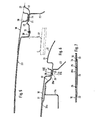
- 10 denotes the roof of a motor vehicle, for. B. a passenger car.
- the roof 10 has an approximately rectangular opening 11, which is provided for a sliding roof (not shown).
- a sliding roof frame 12 is used to hold and guide the sliding roof, the details of which are shown in FIGS. 3-7.
- the sunroof frame designated as a whole by 12
- the upper frame part 13 has an approximately horizontally bent edge 15 to which a frame lower part 17 is fastened, preferably by means of self-tapping screws 16.
- the lower frame part 17 serves. for immediate mounting and guidance of the sunroof, not shown.
- a headliner 18 is attached, which carries a headliner 19.
- the vehicle roof 10 has lateral roof flanges 20 which are bent down like a groove and can also serve as a rain gutter for the vehicle roof 10.
- the side roof flanges 20 also serve to connect the vehicle roof 10 to the upper side members 21 of the vehicle side walls.
- the upper side members 21 are formed in the usual way by an outer side wall 22 and an inner side wall 23.
- the upper longitudinal members 21 each form an inwardly directed, approximately horizontally arranged flange 24, which is spot welded at 25 to the associated lateral roof flanges 20.
- the sunroof frame 12, or its upper frame part 13 is reinforced at the rear end of the sunroof recess 11 by a reinforcing rail 26.
- the part 26, hereinafter referred to as the "front reinforcing rail”, is connected in one piece to the upper frame part 13 and forms a flange 27 which is bent downward in a groove-like manner and to which the already mentioned lower frame part 17 is fastened by screws 16.
- the front reinforcing rail 26 can also be connected to the vehicle roof 10 in the central region thereof by spot welding.
- Fig. 4 also reveals that the front reinforcing rail 26 integrally connected to the frame upper part 13 each has an approximately horizontally bent edge 28 on both sides, which - also at 25 - with the associated lateral roof flange 20 and the inward flange 24 of the associated upper side member 21 is spot welded.
- the spot weld 25 thus connects the vehicle roof 10, sunroof frame 12 and vehicle side walls 21 to one another at the same connection point.
- the sunroof frame 12 also has a rear reinforcement rail, which is designated by 29.
- FIG. 5 shows that the rear reinforcing rail 29 is connected in the same way as the front reinforcing rail 26 on the one hand to the lower frame part 17, on the other hand to the side roof flange 20 and the horizontally arranged flange 24 of the front longitudinal member 21 of the associated vehicle side wall.
- the entire width of the reinforcement rail 29 supporting the vehicle roof 10 can alternatively also be provided on two lateral support supports which can end approximately at the dashed line 30 (FIG. 5).
- the design of such support supports can correspond in detail to the configuration of the rear reinforcing rail 29 in the area to the right of the line 30, as can be seen in FIG. 5.
- FIGS. 6 and 7 show a variant which is somewhat modified compared to the embodiment according to FIGS. 3-5.
- the rear reinforcement rail, here numbered 29a has a downward bend 31 in the roof area, to which the lower frame part 17a is fastened by spot welding.
- the side edge 28a of the rear reinforcing rail 29a is then formed by a further offset 32, which - as in the embodiment according to FIGS. 3-5 - with the lateral roof flange 20 and the inwardly directed, approximately horizontally arranged flange 24 of the upper longitudinal member 21 the vehicle side wall is spot welded.
- a special feature of this embodiment is further that the inner side wall plate 23 and the outer side wall plate 22 of the upper side member 21 - as shown in FIG. 7 - have embossments 33, 34 at the point 25 of the spot weld connection in order to be suitable for the spot welding to be carried out Way to allow centering of the parts 10, 28a, 22 and 23 to be connected.
- Fig. 7 shows a further peculiarity of the embodiment of FIGS. 6 and 7.
- the inner side wall plate 23 forming part of the inwardly directed, approximately horizontally arranged flange 24 is formed recessed in the area of the spot welds 25 (recess 35). This measure avoids spot welding through four sheet thicknesses.
- the spot weld 25 comprises only three sheet thicknesses, namely the parts 10, 28a and 22.
- a connection of the plates 22, 23 in the region of the flange 24 by spot welding is carried out separately at other points anyway.
Landscapes
- Engineering & Computer Science (AREA)
- Mechanical Engineering (AREA)
- Body Structure For Vehicles (AREA)
Applications Claiming Priority (2)
| Application Number | Priority Date | Filing Date | Title |
|---|---|---|---|
| DE3222419 | 1982-06-15 | ||
| DE3222419A DE3222419C2 (de) | 1982-06-15 | 1982-06-15 | Dachaufbau für Kraftfahrzeuge mit Schiebedach, insbesondere Personenkraftwagen |
Publications (3)
| Publication Number | Publication Date |
|---|---|
| EP0096846A2 true EP0096846A2 (fr) | 1983-12-28 |
| EP0096846A3 EP0096846A3 (en) | 1987-07-22 |
| EP0096846B1 EP0096846B1 (fr) | 1989-01-11 |
Family
ID=6166080
Family Applications (1)
| Application Number | Title | Priority Date | Filing Date |
|---|---|---|---|
| EP83105646A Expired EP0096846B1 (fr) | 1982-06-15 | 1983-06-09 | Carrosserie pour véhicules automobiles notamment pour voitures particulières et procédé de fabrication d'une telle carrosserie |
Country Status (2)
| Country | Link |
|---|---|
| EP (1) | EP0096846B1 (fr) |
| DE (2) | DE3222419C2 (fr) |
Cited By (1)
| Publication number | Priority date | Publication date | Assignee | Title |
|---|---|---|---|---|
| CN111278671A (zh) * | 2017-04-20 | 2020-06-12 | 标致雪铁龙汽车股份有限公司 | 机动车辆的车身结构 |
Families Citing this family (12)
| Publication number | Priority date | Publication date | Assignee | Title |
|---|---|---|---|---|
| DE3545870C2 (de) * | 1985-12-23 | 1993-12-09 | Webasto Werk Baier Kg W | Fahrzeugschiebedach |
| DE3624642A1 (de) * | 1986-07-22 | 1988-01-28 | Farmont Rolf | Verfahren, vorrichtung, system und befestigungselement zum lagegerechten einbau von fahrzeugdachfenstern |
| DE8906155U1 (de) * | 1989-02-28 | 1989-08-03 | Eichmüller, Hartmut, Dr., 8110 Riegsee | Kleintransporterkarosserie mit hohem Dach |
| DE4428913C2 (de) | 1994-08-16 | 1997-08-21 | Webasto Karosseriesysteme | Dachaufbau für ein Fahrzeug |
| DE19517645B4 (de) * | 1995-05-17 | 2007-06-21 | Meritor Light Vehicle Systems, Inc., Troy | Schiebedach sowie Verfahren und Vorrichtung zur Montage eines Schiebedachs |
| DE19919505A1 (de) * | 1999-04-29 | 2000-11-02 | Webasto Vehicle Sys Int Gmbh | Fahrzeugdach mit eingesetztem Dachmodul und Montageverfahren dafür |
| DE10022915A1 (de) | 2000-05-11 | 2001-11-22 | Webasto Vehicle Sys Int Gmbh | Fahrzeugdach mit einklebbarem Dachmodul |
| DE10219637B4 (de) * | 2002-05-02 | 2004-11-04 | Webasto Vehicle Systems International Gmbh | Dachöffnungssystem, Dachmodul sowie Kraftfahrzeug mit verbesserter Seitenaufprallstabilität |
| DE10326301B4 (de) * | 2003-06-12 | 2012-08-16 | GM Global Technology Operations LLC (n. d. Ges. d. Staates Delaware) | Fahrzeugdach mit mehrteiligem, aus separaten Sonnen- und/oder Schiebedachsegmenten bestehendem Sonnen- und/oder Schiebedach, sowie hiermit ausgestattetes Fahrzeug |
| DE102006012252A1 (de) * | 2006-03-15 | 2007-09-27 | Johnson Controls Headliner Gmbh | Ausstattungsteil für ein Kraftfahrzeug mit einer Öffnung und einem Anlageteil |
| DE102009010913A1 (de) | 2009-02-27 | 2010-09-02 | Dr.Ing.H.C.F.Porsche Aktiengesellschaft | Baukastensystem für eine Kraftfahrzeugkarosserie |
| WO2017032533A1 (fr) | 2015-08-27 | 2017-03-02 | Webasto SE | Ensemble pour un toit de véhicule, procédé de montage d'un ensemble pour un toit de véhicule et système pour un véhicule à moteur |
Family Cites Families (3)
| Publication number | Priority date | Publication date | Assignee | Title |
|---|---|---|---|---|
| DE2809379C2 (de) * | 1978-03-04 | 1987-01-02 | Dr.Ing.H.C. F. Porsche Ag, 7000 Stuttgart | Dachaufbau für Kraftfahrzeuge, insbesondere Personenwagen, mit einem einen Rahmenboden aufweisenden Schiebedach |
| JPS586728Y2 (ja) * | 1978-09-06 | 1983-02-05 | 本田技研工業株式会社 | 車輌のスライディングル−フ装置におけるル−フ構造 |
| JPS619815Y2 (fr) * | 1980-07-04 | 1986-03-28 |
-
1982
- 1982-06-15 DE DE3222419A patent/DE3222419C2/de not_active Expired
-
1983
- 1983-06-09 EP EP83105646A patent/EP0096846B1/fr not_active Expired
- 1983-06-09 DE DE8383105646T patent/DE3378903D1/de not_active Expired
Cited By (1)
| Publication number | Priority date | Publication date | Assignee | Title |
|---|---|---|---|---|
| CN111278671A (zh) * | 2017-04-20 | 2020-06-12 | 标致雪铁龙汽车股份有限公司 | 机动车辆的车身结构 |
Also Published As
| Publication number | Publication date |
|---|---|
| DE3222419A1 (de) | 1983-12-15 |
| DE3378903D1 (en) | 1989-02-16 |
| EP0096846B1 (fr) | 1989-01-11 |
| DE3222419C2 (de) | 1986-07-31 |
| EP0096846A3 (en) | 1987-07-22 |
Similar Documents
| Publication | Publication Date | Title |
|---|---|---|
| DE102007006722C5 (de) | Träger für eine Karosserie eines Kraftwagens | |
| DE976332C (de) | Fahrzeugunterrahmen, insbesondere kombinierter Fahrgestell- und Wagenkasten-Unterrahmen | |
| EP1928724A1 (fr) | Carrosserie de vehicule automobile dotee d'un support adaptateur destine a un module toit, support adaptateur utilise et procede de production | |
| EP0096846B1 (fr) | Carrosserie pour véhicules automobiles notamment pour voitures particulières et procédé de fabrication d'une telle carrosserie | |
| DE19603954C2 (de) | Prallträger für ein Kraftfahrzeug | |
| DE102015203309B4 (de) | Fahrzeug-Karosseriestruktur | |
| DE2555107A1 (de) | Fahrgestellrahmen fuer kraftfahrzeuge | |
| EP0803389A2 (fr) | Porte de véhicule | |
| DE3815610C2 (de) | Vorderer oberer Querträger einer Kraftfahrzeugkarosserie im Bereich des Windlaufs | |
| DE10158742A1 (de) | Rahmenstruktur eines Fahrzeugdaches und Fahrzeugdach mit einer Rahmenstruktur | |
| EP1108640B1 (fr) | Fixation de toiture de véhicules automobiles | |
| DE19713317A1 (de) | Heckklappe | |
| DE19651627B4 (de) | Unterbaustruktur einer Kraftfahrzeugkarosserie | |
| DE3446734A1 (de) | Kastenkonstruktion, insbesondere fuer nutzfahrzeuge wie brandschutzfahrzeuge | |
| DE3831480C2 (fr) | ||
| DE4139331A1 (de) | Tunnelausbildung in der bodenstruktur einer karosserie eines personenkraftwagens | |
| DE102005039464A1 (de) | A-Säule für ein Kraftfahrzeug | |
| DE19724557B4 (de) | Selbsttragende Fahrzeugkarosserie | |
| DE19731342B4 (de) | Kastenförmiger Längsträger für ein Kraftfahrzeug | |
| DE976568C (de) | Wagenkasten fuer Kraftfahrzeuge selbsttragender Bauweise | |
| DE967939C (de) | Bodenblechrahmen als Bestandteil selbsttragender Fahrzeugwagenkaesten | |
| DE544563C (de) | Wagenkasten, insbesondere fuer Kraftfahrzeuge | |
| DE102004001747A1 (de) | Fahrzeugkarosserie mit einer Rohbaustruktur | |
| DE10116437A1 (de) | Karosserie eines Fahrzeuges | |
| DE4316095A1 (de) | Kraftfahrzeugaufbau mit einem Plattformrahmen |
Legal Events
| Date | Code | Title | Description |
|---|---|---|---|
| PUAI | Public reference made under article 153(3) epc to a published international application that has entered the european phase |
Free format text: ORIGINAL CODE: 0009012 |
|
| AK | Designated contracting states |
Designated state(s): DE FR GB IT NL |
|
| 17P | Request for examination filed |
Effective date: 19840509 |
|
| PUAL | Search report despatched |
Free format text: ORIGINAL CODE: 0009013 |
|
| AK | Designated contracting states |
Kind code of ref document: A3 Designated state(s): DE FR GB IT NL |
|
| 17Q | First examination report despatched |
Effective date: 19880622 |
|
| ITF | It: translation for a ep patent filed | ||
| GRAA | (expected) grant |
Free format text: ORIGINAL CODE: 0009210 |
|
| AK | Designated contracting states |
Kind code of ref document: B1 Designated state(s): DE FR GB IT NL |
|
| GBT | Gb: translation of ep patent filed (gb section 77(6)(a)/1977) | ||
| REF | Corresponds to: |
Ref document number: 3378903 Country of ref document: DE Date of ref document: 19890216 |
|
| ET | Fr: translation filed | ||
| PLBE | No opposition filed within time limit |
Free format text: ORIGINAL CODE: 0009261 |
|
| STAA | Information on the status of an ep patent application or granted ep patent |
Free format text: STATUS: NO OPPOSITION FILED WITHIN TIME LIMIT |
|
| 26N | No opposition filed | ||
| PGFP | Annual fee paid to national office [announced via postgrant information from national office to epo] |
Ref country code: NL Payment date: 19930630 Year of fee payment: 11 |
|
| ITTA | It: last paid annual fee | ||
| REG | Reference to a national code |
Ref country code: GB Ref legal event code: 746 Effective date: 19940708 |
|
| PG25 | Lapsed in a contracting state [announced via postgrant information from national office to epo] |
Ref country code: NL Effective date: 19950101 |
|
| NLV4 | Nl: lapsed or anulled due to non-payment of the annual fee | ||
| PGFP | Annual fee paid to national office [announced via postgrant information from national office to epo] |
Ref country code: GB Payment date: 20010601 Year of fee payment: 19 |
|
| PGFP | Annual fee paid to national office [announced via postgrant information from national office to epo] |
Ref country code: FR Payment date: 20010621 Year of fee payment: 19 |
|
| PGFP | Annual fee paid to national office [announced via postgrant information from national office to epo] |
Ref country code: DE Payment date: 20010824 Year of fee payment: 19 |
|
| REG | Reference to a national code |
Ref country code: GB Ref legal event code: IF02 |
|
| PG25 | Lapsed in a contracting state [announced via postgrant information from national office to epo] |
Ref country code: GB Free format text: LAPSE BECAUSE OF NON-PAYMENT OF DUE FEES Effective date: 20020609 |
|
| PG25 | Lapsed in a contracting state [announced via postgrant information from national office to epo] |
Ref country code: DE Free format text: LAPSE BECAUSE OF NON-PAYMENT OF DUE FEES Effective date: 20030101 |
|
| GBPC | Gb: european patent ceased through non-payment of renewal fee |
Effective date: 20020609 |
|
| PG25 | Lapsed in a contracting state [announced via postgrant information from national office to epo] |
Ref country code: FR Free format text: LAPSE BECAUSE OF NON-PAYMENT OF DUE FEES Effective date: 20030228 |
|
| REG | Reference to a national code |
Ref country code: FR Ref legal event code: ST |