EP0096876B1 - Dispositif de commande pour inverseurs de poussée - Google Patents
Dispositif de commande pour inverseurs de poussée Download PDFInfo
- Publication number
- EP0096876B1 EP0096876B1 EP83105731A EP83105731A EP0096876B1 EP 0096876 B1 EP0096876 B1 EP 0096876B1 EP 83105731 A EP83105731 A EP 83105731A EP 83105731 A EP83105731 A EP 83105731A EP 0096876 B1 EP0096876 B1 EP 0096876B1
- Authority
- EP
- European Patent Office
- Prior art keywords
- extension
- compressed air
- thrust
- piston
- valve
- Prior art date
- Legal status (The legal status is an assumption and is not a legal conclusion. Google has not performed a legal analysis and makes no representation as to the accuracy of the status listed.)
- Expired
Links
- 238000006073 displacement reaction Methods 0.000 claims description 3
- 238000009877 rendering Methods 0.000 claims description 2
- 230000008878 coupling Effects 0.000 claims 1
- 238000010168 coupling process Methods 0.000 claims 1
- 238000005859 coupling reaction Methods 0.000 claims 1
- 230000005540 biological transmission Effects 0.000 description 2
- 230000001427 coherent effect Effects 0.000 description 1
- 230000001419 dependent effect Effects 0.000 description 1
- 238000011161 development Methods 0.000 description 1
- 230000018109 developmental process Effects 0.000 description 1
- 238000007599 discharging Methods 0.000 description 1
- 238000005096 rolling process Methods 0.000 description 1
- 230000001360 synchronised effect Effects 0.000 description 1
Images


Classifications
-
- F—MECHANICAL ENGINEERING; LIGHTING; HEATING; WEAPONS; BLASTING
- F02—COMBUSTION ENGINES; HOT-GAS OR COMBUSTION-PRODUCT ENGINE PLANTS
- F02K—JET-PROPULSION PLANTS
- F02K1/00—Plants characterised by the form or arrangement of the jet pipe or nozzle; Jet pipes or nozzles peculiar thereto
- F02K1/54—Nozzles having means for reversing jet thrust
- F02K1/76—Control or regulation of thrust reversers
Definitions
- the invention relates to a device according to the preamble of claim 1.
- a device of this type known from DE-A-2413 702 but as a single device, i. H. for a thrust reverser of a jet engine, it is about facilitating the unlocking of a locking device for the thrust reverser for extending the same.
- a device with a servomotor, a valve, etc. is assumed - for each of the two jet engines, a single device is provided - and the problem is that the two thrust reversers generally extend at different speeds, especially due to different air leaks at the two input pistons, different friction in the two differential gears and in bearings and flexible flap drive shafts of the two individual devices and different values of the air delivery pressure for the two individual devices.
- Those different air leaks exert a very large influence in this regard, because of the small working volume in the cylinders for the input pistons.
- Those bearings are in particular bearings of the differential gears, the piston rods of the input pistons and levers on the differential gears.
- the object of the invention is to make the difference between the extension speeds of the two thrust reversers as small as possible or to make them practically disappear.
- the training or design according to claim 2 is relatively simple, and it works reliably.
- the extension interruption stops are, in particular, pneumatically controllable stops, and the means for rendering them ineffective are, in particular, air valves. But it can also be electrical stops and means, for. B. in electric motors as a setpoint generator.
- the embodiment according to claim 3 shows a simple structure of the pneumatically controllable stops and easy controllability of the same.
- the electromagnetic controllability of the air valves according to claim 4 contributes to the simplicity and reliability of the synchronization device or represents the prerequisite for simple and safe control of the stops or the air valves by electrical means.
- the electrical position transmitter reproduced in claim 5 and the electrical mentioned there AND gates are simple and reliable means of simultaneously canceling the extension interruption for both thrust reversers. Claim 6 indicates where the location of the exit interruption is in particular.
- the mechanical and electrical parts of the synchronization device listed in the subclaims are simple and reliable and also easy to install.
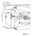
- an embodiment of the adjusting devices according to the invention is shown schematically. It is a coherent figure formed from illustrations on three sheets (sheets 1 to 3). To simplify matters, the adjustment device is shown broken off on the left. What has been omitted consists essentially - see also later - for each individual device of a shut-off valve, a directional selection valve and a sequence valve and associated air or compressed air lines.
- This device for adjusting the two thrust reversers or two flaps (thrust reverser flaps) 24 of the same has two identical rotary piston or air motors 20 operated by compressed air. These each have two rotating bodies 25 and 26, the directions of rotation of which can be reversed together. For the sake of simplicity, only one of the two air motors 20 is shown. Each air motor 20 actuates its thrust reverser, specifically the flaps 24 can be extended and retracted by the rotating bodies 25, 26 via a flexible shaft 21 and a transmission device 28, depending on the direction of rotation of the rotating bodies 25, 26. The flaps 24 are fully retracted once and, furthermore, 75% of the entire travel range is shown in dash-dot lines.
- the axial paths of two identical ball rolling spindles 29 (only one is shown) working in parallel with one another of the transmission device 28 are linearly dependent on the actuating or rotating path or the number of revolutions of the rotating bodies 25, 26; A certain position or angular position of the flaps 24 is assigned to each point of this path or each number of revolutions.
- the adjusting device also has a rotary slide valve 23 for controlling the compressed air for each air motor 20 on. Both rotary slide valves 23 are the same.
- the air motor 20 and the rotary slide valve 23 together with two channels 32 and 33 connecting them form a structural unit.
- the compressed air can be fed to the rotary slide valve 23 from a compressor of the associated jet engine via an inflow line 41, which has the aforementioned shutoff valve (not shown).
- valve 27 By means of a rotary valve 27, two diametrically opposite valve flow cross sections 30 and 31 of equal size can be controlled, and depending on the opening direction of rotation of the rotary valve 27, the rotary bodies 25, 26 can be driven in their one or their opposite direction of rotation by the compressed air.
- the outlet air flows out through an outflow line 34.
- the adjusting device also has two identical input pistons (setpoint pistons or time-setting pistons) 18 and 19 for actuating the rotary slide valves 23.
- the rotary valve 27 is actuated by the associated input piston 18 or 19, which is displaceable or controllable in a cylinder 35 by pressurized air or by its piston rod 65, which penetrates an end wall 16 of the cylinder 35, via a differential gear 36, which is connected to the associated air motor 20 can be influenced via a feedback 37 having a step-down feedback gear (worm gear) 39. If the input piston 18 or 19 is pressurized with compressed air at the top in its illustrated, upper position, it is moved downward to the end wall 16 and the flaps 24 are extended.
- worm gear step-down feedback gear
- the air motor 20, the rotary slide valve 23 and the differential gear 36 together act as a follow-up device which follows the movement of the input piston 18 and 19, respectively. It is a positioner.
- the position of a lever 48 on the differential gear 36 is a measure of the control deviation.
- a slide valve 49 prevents the control deviation from increasing beyond an impermissible level.
- an air line 59 leads to the throttle openings 38 and 46 and to the check valve 44 and an air line 22 leads to the throttle openings 40 and 47 and to the check valve 45.
- the desired input piston Direction of movement for extending or retracting the thrust reverser is achieved for each input piston 18 or 19 by appropriate setting of the associated direction selector valve, not shown, by means of compressed air via the sequence valve.
- the adjustment device has an extension synchronization device for the two thrust reversers or their flaps 24.
- the extension synchronization device has two identical, pneumatically controllable extension interruption stops 10 and 11 for the same counter stop pieces 12 and 13 which can be moved with the input pistons 18 and 19.
- the counter-striking piece 12 or 13 is fixedly provided on the piston rod 65.
- a housing 15 is provided on the drawing below, in which u. a. the counter stop piece 12 or 13 and the differential gear 36.
- the stop 10 or 11 has a cylinder which is coaxial with the input piston 18 or 19 and consists of a cylinder wall 14 and two end walls 52 and 53, and the housing 15 is connected at the bottom, in one piece with it, to the end wall 52 and the cylinder wall 14 .
- such a cylinder (14, 52, 53) is retrofitted to the housing 15 at the bottom, preferably by means of threaded connectors screwed together.
- a piston 17 This is on the part of a central pin 55 facing the input piston 18 or 19 of a coaxial screwed through the end wall 53, projecting into the interior of the cylinder 14, 52, 53
- Adjusting nut 54 through which the bolt 55 is screwed with its other part, can be displaced by the application of compressed air up to a stop 72 of the bolt 55 and can be held there.
- a coaxial stop sleeve 56 which leads through the end wall 52 and is closed towards the counter stop piece 13, is placed over the first-mentioned part of the bolt 55 and forms a fixed unit with the piston 17.
- Each of the two adjusting nuts 54 is axially adjusted so that when the piston 17 bears against the adjusting nut 54, the distance between it and the stop 72 is 25% of the total travel of the input piston 18 or 19.
- the distance between the counter-stop piece 12 or 13 and the stop sleeve 56 is equal to this total adjustment path. This distance is reduced to 75% by the displacement of the piston 17 from the adjusting nut 54 to the stop 72, that is to say the displacement of the stop sleeve 56 into its stop position.
- valves 57 and 58 each have an electromagnet 69 and a compressed air discharge line 51.
- a check valve 66 is provided in the air line 60 or 68 between the valve 57 or 58 and the cylinder 14, 52, 53, and an air line 61 bypassing the check valve 66 is also provided, which is used to discharge the compressed air from the cylinder 14, 52, 53 goes out, contains a throttle point 43 and between the check valve 66 and the valve 57 or 58 opens into the air line 60 or 68.
- the two electromagnets 69 receive electrical current via an electrical device 71, then the two valves 57 and 58 are simultaneously opened by the electromagnets 69 against spring forces and with one another for the above-mentioned action and closed with respect to the above-mentioned discharge, so that the compressed air through the air lines 60 and 68 - see flow direction arrows 50 and 76 - and the open check valves 66 flow into the cylinders 14, 52, 53 and act on the pistons 17 and thus bring them and the stop sleeves 56 into the stop position and hold them.
- the extension synchronization device has an electric position transmitter 62 or 63 for each thrust reverser, which is fixedly attached to the associated jet engine and can be actuated by a lever 64 of an adjusting lever device of the thrust reverser during the extension of the flaps 24.
- the position transmitter 62 or 63 is mounted so that the actuation of the same is carried out by the associated lever 64 shortly before the associated thrust reverser has reached the position caused by the impact of the associated counter stop piece 12 or 13 on the corresponding stop sleeve located in the stop position 56 is determined.
- the two position signals of the two position transmitters 62 and 63 are present on an electrical AND gate 67 of the electrical device 71 into which they are input , which means that both thrust reversers have reached the positions determined by said impact, the electrical current for the two electromagnets 69 is simultaneously switched off at the same time.
- both valves 57 and 58 are closed simultaneously to release the pressurization and opened for draining by said spring forces and with one another, so that the compressed air from the cylinders 14, 52, 53 with the check valves 66 closed through the air lines 61, the air lines 60 and 68, the valves 57 and 58 and the compressed air discharge lines 51 escape - see the outflow arrows 74 and 75.
- the extension interruption for both thrust reversers is canceled at the same time.
- the units consisting of the stop sleeve 56 and the piston 17 can reach the nuts 54 practically without resistance.
- both stop sleeves 56 are deactivated with each other at the same time, and both thrust reversers begin the reverse thrust phase, i.e. the last 25 percent of the total actuating or extension path , at the same time, whereby they reach their extended end positions practically simultaneously.
- An electrical time delay element 70 of the device 71 can be used to set a desired or necessary time period between the arrival of the remaining thrust reverser at the exit interruption point and the common restart of the two thrust reversers, so that the two signals present at the AND gate 67 are only switched through after this time period will. This period is generally very short.
- the pilot can actuate an override device 73 to influence the AND gate 67 in such a way that the circuit to the electromagnets 69 is interrupted and thus the synchronization connection between the two thrust reverser systems or Individual facilities is canceled.
- the override device 73 is located in the electrical circuit 77 between the AND gate 67 and the directional Y selection valve.
Landscapes
- Engineering & Computer Science (AREA)
- Chemical & Material Sciences (AREA)
- Combustion & Propulsion (AREA)
- Mechanical Engineering (AREA)
- General Engineering & Computer Science (AREA)
- Gear-Shifting Mechanisms (AREA)
- Fluid-Pressure Circuits (AREA)
- Electrical Discharge Machining, Electrochemical Machining, And Combined Machining (AREA)
- Warping, Beaming, Or Leasing (AREA)
- Compression-Type Refrigeration Machines With Reversible Cycles (AREA)
Claims (6)
Applications Claiming Priority (2)
| Application Number | Priority Date | Filing Date | Title |
|---|---|---|---|
| DE3222672A DE3222672C1 (de) | 1982-06-16 | 1982-06-16 | Einrichtung zum Verstellen von Schubumkehrern |
| DE3222672 | 1982-06-16 |
Publications (3)
| Publication Number | Publication Date |
|---|---|
| EP0096876A2 EP0096876A2 (fr) | 1983-12-28 |
| EP0096876A3 EP0096876A3 (en) | 1985-04-03 |
| EP0096876B1 true EP0096876B1 (fr) | 1987-04-15 |
Family
ID=6166214
Family Applications (1)
| Application Number | Title | Priority Date | Filing Date |
|---|---|---|---|
| EP83105731A Expired EP0096876B1 (fr) | 1982-06-16 | 1983-06-11 | Dispositif de commande pour inverseurs de poussée |
Country Status (4)
| Country | Link |
|---|---|
| US (1) | US4522358A (fr) |
| EP (1) | EP0096876B1 (fr) |
| JP (1) | JPS593151A (fr) |
| DE (1) | DE3222672C1 (fr) |
Families Citing this family (8)
| Publication number | Priority date | Publication date | Assignee | Title |
|---|---|---|---|---|
| US4827248A (en) * | 1987-06-30 | 1989-05-02 | The Boeing Company | Proximity sensor with automatic gap control |
| RU2152528C1 (ru) * | 1995-12-28 | 2000-07-10 | Дзе Боинг Компани | Система запирания вала синхронизации устройства реверсирования тяги и замок вала синхронизации устройства реверсирования тяги |
| FR2755730B1 (fr) * | 1996-11-14 | 1999-01-08 | Hispano Suiza Sa | Systeme de commande electrique pour inverseur de poussee de turboreacteur |
| FR2846377B1 (fr) * | 2002-10-25 | 2006-06-30 | Hispano Suiza Sa | Inverseur de poussee electromecanique pour turboreacteur a controle permanent de position |
| GB0817775D0 (en) | 2008-09-29 | 2008-11-05 | Goodrich Actuation Systems Ltd | Actuator |
| GB0906392D0 (en) | 2009-04-15 | 2009-05-20 | Goodrich Actuation Systems Ltd | Thrust reverser actuator system |
| FR3027066A1 (fr) * | 2014-10-14 | 2016-04-15 | Aircelle Sa | Inverseur de poussee pour nacelle de turboreacteur d'aeronef et nacelle associee |
| US11855581B2 (en) * | 2017-07-18 | 2023-12-26 | Polar Racking Inc. | Solar panel support and drive system |
Family Cites Families (12)
| Publication number | Priority date | Publication date | Assignee | Title |
|---|---|---|---|---|
| GB582832A (en) * | 1944-09-02 | 1946-11-28 | Cyril Daniel Watson | Improvements in and relating to hydraulic power presses |
| US2706886A (en) * | 1950-06-14 | 1955-04-26 | Honeywell Regulator Co | Coordinated hydraulic control apparatus |
| US3015936A (en) * | 1957-06-03 | 1962-01-09 | Curtiss Wright Corp | Thrust reversers |
| US3192711A (en) * | 1962-11-29 | 1965-07-06 | Bob C Miller | Nozzle position and afterburner lighting indicator |
| US3655134A (en) * | 1970-11-23 | 1972-04-11 | Hobson Ltd H M | Jet engines for aircraft |
| GB1334518A (en) * | 1971-01-14 | 1973-10-17 | Rotax Ltd | Actuating systems of thrust reversal buckets for a gas turbine engine |
| GB1419403A (fr) * | 1973-03-21 | 1975-12-31 | ||
| DE2354747A1 (de) * | 1973-11-02 | 1975-05-07 | Motoren Turbinen Union | Vorrichtung zur steuerung einer schubumkehrvorrichtung |
| PT68274A (en) * | 1978-07-11 | 1978-08-01 | A A Ribeiro De Almeida | Device applicable to presses and metal bending presses to syncronize the movements of the hydraulic cylinders and control slider cross member |
| GB2082800B (en) * | 1980-07-18 | 1983-12-07 | Bendix Corp | Integrated hydraulic control system |
| FR2488335B1 (fr) * | 1980-08-11 | 1986-01-31 | Snecma | Dispositif detecteur de position d'un inverseur de poussee de turboreacteur et de son verrouillage |
| US4391409A (en) * | 1980-09-30 | 1983-07-05 | The Boeing Company | Positioning and control system for fan thrust reverser cowls in a turbofan engine |
-
1982
- 1982-06-16 DE DE3222672A patent/DE3222672C1/de not_active Expired
-
1983
- 1983-06-11 EP EP83105731A patent/EP0096876B1/fr not_active Expired
- 1983-06-13 US US06/503,695 patent/US4522358A/en not_active Expired - Fee Related
- 1983-06-16 JP JP58106821A patent/JPS593151A/ja active Pending
Also Published As
| Publication number | Publication date |
|---|---|
| EP0096876A2 (fr) | 1983-12-28 |
| DE3222672C1 (de) | 1984-01-19 |
| US4522358A (en) | 1985-06-11 |
| JPS593151A (ja) | 1984-01-09 |
| EP0096876A3 (en) | 1985-04-03 |
Similar Documents
| Publication | Publication Date | Title |
|---|---|---|
| EP0096880B1 (fr) | Dispositif de commande pour inverseurs de poussée | |
| EP0077984B1 (fr) | Dispositif de commande de positionnement | |
| DE2930219C2 (de) | Schubumkehr-Steuervorrichtung für Strahltriebwerke | |
| EP2208875B1 (fr) | Dispositif de soupape et moteur à combustion interne. | |
| EP0064249A1 (fr) | Commande de positionnement pour aiguillages | |
| EP1316716A2 (fr) | Système d'admission pour un moteur à combustion interne avec alimentation par impulsions | |
| DE3222672C1 (de) | Einrichtung zum Verstellen von Schubumkehrern | |
| DE2413702C2 (de) | Schubumlenkvorrichtung für ein Flugzeug-Düsentriebwerk | |
| EP1114918B1 (fr) | Commande de soupape pour moteur à combustion interne et mode d'opération | |
| DE102008010571A1 (de) | Elektromotorisch angesteuertes Ventil | |
| DE2354747A1 (de) | Vorrichtung zur steuerung einer schubumkehrvorrichtung | |
| DE1451969B1 (de) | Regeleinrichtung für Brennstoffeinspritzpumpen von Brennkraftmaschinen | |
| EP0822334B1 (fr) | Pompe à engrenages | |
| DE1426480B2 (de) | Anlage fuer die steuerung hydraulischer stellmotoren | |
| DE1426480C (de) | Anlage fur die Steuerung hydraulischer Stellmotoren | |
| DE2450330A1 (de) | Doppelhydraulischer stellantrieb | |
| DE172511C (fr) | ||
| DE1300444B (de) | Pneumatisch betaetigbare UEbergabesicherung zwischen zwei oder mehr Steuerstaenden einer umsteuerbaren Antriebsanlage | |
| DE1259163B (de) | Durch Drehbewegungen betaetigtes Steuerventil | |
| DE1476030C (de) | Vorrichtung zum automatischen Abschal ten von an explosionsgefahrdeten Orten ar beiienden Brennkraftmaschinen | |
| DE2108545C (de) | Doppelhydraulischer Stellantrieb | |
| DE722482C (de) | Einrichtung zum Regeln von Brennkraftmaschinen | |
| CH393479A (de) | Steuervorrichtung für Überschaltschütze bei Einphasen-Wechselstrom-Stufenschaltern | |
| DE1145493B (de) | Einrichtung fuer die Steuerung einer periodisch arbeitenden druckmittelbetriebenen Vorrichtung | |
| DE1253511B (de) | Vorrichtung zum Anlassen einer Kolbenbrennkraftmaschine |
Legal Events
| Date | Code | Title | Description |
|---|---|---|---|
| PUAI | Public reference made under article 153(3) epc to a published international application that has entered the european phase |
Free format text: ORIGINAL CODE: 0009012 |
|
| AK | Designated contracting states |
Designated state(s): FR GB IT SE |
|
| PUAL | Search report despatched |
Free format text: ORIGINAL CODE: 0009013 |
|
| AK | Designated contracting states |
Designated state(s): FR GB IT SE |
|
| 17P | Request for examination filed |
Effective date: 19850502 |
|
| ITF | It: translation for a ep patent filed | ||
| GRAA | (expected) grant |
Free format text: ORIGINAL CODE: 0009210 |
|
| AK | Designated contracting states |
Kind code of ref document: B1 Designated state(s): FR GB IT SE |
|
| ET | Fr: translation filed | ||
| PLBE | No opposition filed within time limit |
Free format text: ORIGINAL CODE: 0009261 |
|
| STAA | Information on the status of an ep patent application or granted ep patent |
Free format text: STATUS: NO OPPOSITION FILED WITHIN TIME LIMIT |
|
| 26N | No opposition filed | ||
| PGFP | Annual fee paid to national office [announced via postgrant information from national office to epo] |
Ref country code: GB Payment date: 19930512 Year of fee payment: 11 |
|
| PGFP | Annual fee paid to national office [announced via postgrant information from national office to epo] |
Ref country code: FR Payment date: 19930519 Year of fee payment: 11 |
|
| PGFP | Annual fee paid to national office [announced via postgrant information from national office to epo] |
Ref country code: SE Payment date: 19930524 Year of fee payment: 11 |
|
| ITTA | It: last paid annual fee | ||
| PG25 | Lapsed in a contracting state [announced via postgrant information from national office to epo] |
Ref country code: GB Effective date: 19940611 |
|
| PG25 | Lapsed in a contracting state [announced via postgrant information from national office to epo] |
Ref country code: SE Effective date: 19940612 |
|
| EUG | Se: european patent has lapsed |
Ref document number: 83105731.0 Effective date: 19950110 |
|
| GBPC | Gb: european patent ceased through non-payment of renewal fee |
Effective date: 19940611 |
|
| PG25 | Lapsed in a contracting state [announced via postgrant information from national office to epo] |
Ref country code: FR Effective date: 19950228 |
|
| EUG | Se: european patent has lapsed |
Ref document number: 83105731.0 |
|
| REG | Reference to a national code |
Ref country code: FR Ref legal event code: ST |