EP0096909A1 - Dispositif pour renverser la marche des gaz captés au bec des convertisseurs - Google Patents
Dispositif pour renverser la marche des gaz captés au bec des convertisseurs Download PDFInfo
- Publication number
- EP0096909A1 EP0096909A1 EP83200680A EP83200680A EP0096909A1 EP 0096909 A1 EP0096909 A1 EP 0096909A1 EP 83200680 A EP83200680 A EP 83200680A EP 83200680 A EP83200680 A EP 83200680A EP 0096909 A1 EP0096909 A1 EP 0096909A1
- Authority
- EP
- European Patent Office
- Prior art keywords
- gas
- valves
- pressure
- gasometer
- switching
- Prior art date
- Legal status (The legal status is an assumption and is not a legal conclusion. Google has not performed a legal analysis and makes no representation as to the accuracy of the status listed.)
- Granted
Links
- 239000002184 metal Substances 0.000 claims description 2
- 238000006073 displacement reaction Methods 0.000 abstract 1
- 239000007789 gas Substances 0.000 description 31
- 238000000034 method Methods 0.000 description 6
- 230000008569 process Effects 0.000 description 6
- 230000008901 benefit Effects 0.000 description 2
- 238000007664 blowing Methods 0.000 description 2
- 230000008859 change Effects 0.000 description 2
- 238000011144 upstream manufacturing Methods 0.000 description 2
- QVGXLLKOCUKJST-UHFFFAOYSA-N atomic oxygen Chemical compound [O] QVGXLLKOCUKJST-UHFFFAOYSA-N 0.000 description 1
- 238000004140 cleaning Methods 0.000 description 1
- 238000010276 construction Methods 0.000 description 1
- 230000000694 effects Effects 0.000 description 1
- 238000005516 engineering process Methods 0.000 description 1
- 238000007667 floating Methods 0.000 description 1
- 239000001301 oxygen Substances 0.000 description 1
- 229910052760 oxygen Inorganic materials 0.000 description 1
- 238000007789 sealing Methods 0.000 description 1
- 230000003068 static effect Effects 0.000 description 1
- 230000007704 transition Effects 0.000 description 1
- 210000003462 vein Anatomy 0.000 description 1
Images

Classifications
-
- C—CHEMISTRY; METALLURGY
- C21—METALLURGY OF IRON
- C21C—PROCESSING OF PIG-IRON, e.g. REFINING, MANUFACTURE OF WROUGHT-IRON OR STEEL; TREATMENT IN MOLTEN STATE OF FERROUS ALLOYS
- C21C5/00—Manufacture of carbon-steel, e.g. plain mild steel, medium carbon steel or cast steel or stainless steel
- C21C5/28—Manufacture of steel in the converter
- C21C5/38—Removal of waste gases or dust
- C21C5/40—Offtakes or separating apparatus for converter waste gases or dust
Definitions
- the invention relates to a device for pressure surge-free switching of the gas stream from a converter from flare mode to gasometer mode and vice versa, consisting of a housing with a gas inlet cross section and two gas outlet cross sections, with shut-off devices including drives and with measuring and control devices.
- a CO-containing gas with a calorific value of 8000 or more kJ / N m 3 is generated during the blowing phase, which is collected in modern systems after appropriate cleaning in a gasometer for further use.
- a switchover device must be provided in the exhaust pipe.
- So-called scrubbers can be used to purify the exhaust gases, their pressure loss during the torch drive is about 200 mbar.
- Dry-working electrostatic filters are more advantageous, as they only manage a pressure loss of around 20 mbar during flare operation.
- the pressure loss changes in both cases by, for example, 20 mbar.
- the pressure difference to be overcome by the blower therefore only changes by about 10%, while in systems with dry dedusting, which are preferred because of the much lower energy requirement, the change is about 100%. It is readily apparent that switching from torch to gasometer operation and vice versa is less difficult in terms of control technology in systems with wet gas dedusting than in systems with dry gas dedusting.
- the dedusting device acts like a throttle, so that pressure surges as a result of the switchover upstream can scarcely have an effect up to the area of the suction hood above the converter.
- the changeover device must be designed much more carefully and the control of the blower must work much more precisely if a disturbance in the pressure conditions in the area of the suction hood is to be excluded.
- This known switching device is relatively complex and complicated.
- the main disadvantage is that it has poor control characteristics.
- the known device is unsuitable for systems with dry gas dedusting because the switching process cannot take place without pressure surges and because it also cannot satisfactorily compensate for operational fluctuations in gas pressure and gas flow.
- the bell valves preferably have the same characteristic curve and flow cross sections of the same size. In white It is provided that the bell valves have a metal-metal seal and a closing pressure of at least 3 times the gasometer pressure.
- the device according to the invention has the advantage that only two actuators are required, which simultaneously regulate the switching process and alternately securely seal the two outgoing gas lines.
- the bell valves By designing the bell valves with an equal percentage characteristic curve, the converter gas flow can be switched between the two operating modes without pressure surges.
- the independent actuation of the bell valves ensures that, in addition to overcoming the static pressure in the gasometer line, the required dynamic pressure increase is also mastered, a prerequisite for preventing gases from floating out of the suction hood above the converter during the switchover process .
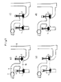
- 10 denotes a housing, into which a gas line 4 opens and from which two gas lines 7 and 8 extend.
- the converter gas is conveyed by means of blowers 3 to the housing 10 and depending on the position of the bell veins tile 1 and 2 passed on via line 7 in the gasometer or via line 8 in the flare 9.
- the drives for the bell valves 1 and 2 are designated.
- valve position corresponds to phase 1 in FIG. 3.
- FIG. 1b The start of the switching process is shown in FIG. 1b. Valve 1 is still complete and valve 2 partially closed. In FIG. 1c, valve 2 is closed further and valve 1 is already partially open.
- FIG. 3 The two representations identify snapshots during the switchover phase 2 according to FIG. 3.
- valve 2 is completely closed, while valve 1 is now fully open.
- the exit cross section to line 8 and to the flare 9 is thus blocked, while the exit cross section to line 7 and thus to the gasometer is fully open.
- the two drives 5 and 6 for the bell valves 1 and 2 work independently of one another and thereby allow an absolutely pressure surge-free transition between the two operating states of the switchover station.
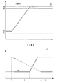
- the two bell valves 1 and 2 have a special contour, as shown once again on a larger scale in FIG. 2a.
- FIG. 2b shows the associated control characteristic curve, the characteristic variable kv being plotted over the stroke.
- FIG. 3a the gas pressure upstream of the valve is, for example, 2 mbar above the external pressure, while in gasometer operation it is, for example, 5 mbar above the gasometer pressure of, for example, 40 mbar.
- Switching to gasometer operation begins with the closing of valve 2 until a certain pressure is reached via valve 1. Then valve 1 opens at a constant speed, valve 2 closing further. Valve 2 is completely closed after valve 1 has reached its open position. When switching to torch mode, valve 1 first moves to the closed position; as soon as this is reached, valve 2 is opened.
- the gas flow from a converter can be switched from torch operation to gasometer operation and vice versa without pressure surges, quickly and reliably.
- the device is comparatively simple in construction and at the same time fulfills control and sealing functions.
Landscapes
- Engineering & Computer Science (AREA)
- Chemical & Material Sciences (AREA)
- Environmental & Geological Engineering (AREA)
- Manufacturing & Machinery (AREA)
- Materials Engineering (AREA)
- Metallurgy (AREA)
- Organic Chemistry (AREA)
- Control Of Fluid Pressure (AREA)
- Flow Control (AREA)
- Chimneys And Flues (AREA)
Applications Claiming Priority (2)
| Application Number | Priority Date | Filing Date | Title |
|---|---|---|---|
| DE3222599 | 1982-06-16 | ||
| DE19823222599 DE3222599A1 (de) | 1982-06-16 | 1982-06-16 | Umschaltvorrichtung fuer einnen konverter-gasstrom |
Publications (2)
| Publication Number | Publication Date |
|---|---|
| EP0096909A1 true EP0096909A1 (fr) | 1983-12-28 |
| EP0096909B1 EP0096909B1 (fr) | 1986-02-26 |
Family
ID=6166187
Family Applications (1)
| Application Number | Title | Priority Date | Filing Date |
|---|---|---|---|
| EP83200680A Expired EP0096909B1 (fr) | 1982-06-16 | 1983-05-13 | Dispositif pour renverser la marche des gaz captés au bec des convertisseurs |
Country Status (3)
| Country | Link |
|---|---|
| EP (1) | EP0096909B1 (fr) |
| JP (1) | JPS596312A (fr) |
| DE (2) | DE3222599A1 (fr) |
Citations (6)
| Publication number | Priority date | Publication date | Assignee | Title |
|---|---|---|---|---|
| DE1433571B (de) * | Kawasaki Jukogyo K K , Kobe, Hyogo (Japan) | Abgasanlage fur Sauerstoff Aufblas konverter | ||
| GB263165A (en) * | 1925-12-16 | 1927-06-09 | Silica En Ovenbouw Mij Nv | Improvements in distributing valves for regenerative ovens or furnaces heated by gas |
| DE481132C (de) * | 1929-08-14 | Karl Wolinski | Hydraulisch betriebene Ventilumsteuerungsvorrichtung fuer regenerativ geheizte OEfen | |
| DE1433688B1 (de) * | 1961-04-10 | 1971-04-01 | Yawata Iron & Steel Co | Vorrichtung zur Gewinnung des unverbrannten Abgases aus einem Sauerstoffaufblaskonverter |
| EP0022683A1 (fr) * | 1979-06-07 | 1981-01-21 | Creusot-Loire Entreprises | Dispositif d'aiguillage des gaz et procédé de fonctionnement d'un tel dispositif |
| DE3043643A1 (de) * | 1980-11-19 | 1982-06-03 | Gottfried Bischoff Bau kompl. Gasreinigungs- und Wasserrückkühlanlagen GmbH & Co KG, 4300 Essen | Anlage fuer die konvertergasspeicherung |
-
1982
- 1982-06-16 DE DE19823222599 patent/DE3222599A1/de not_active Withdrawn
-
1983
- 1983-05-13 EP EP83200680A patent/EP0096909B1/fr not_active Expired
- 1983-05-13 DE DE8383200680T patent/DE3362261D1/de not_active Expired
- 1983-06-13 JP JP58105627A patent/JPS596312A/ja active Granted
Patent Citations (6)
| Publication number | Priority date | Publication date | Assignee | Title |
|---|---|---|---|---|
| DE1433571B (de) * | Kawasaki Jukogyo K K , Kobe, Hyogo (Japan) | Abgasanlage fur Sauerstoff Aufblas konverter | ||
| DE481132C (de) * | 1929-08-14 | Karl Wolinski | Hydraulisch betriebene Ventilumsteuerungsvorrichtung fuer regenerativ geheizte OEfen | |
| GB263165A (en) * | 1925-12-16 | 1927-06-09 | Silica En Ovenbouw Mij Nv | Improvements in distributing valves for regenerative ovens or furnaces heated by gas |
| DE1433688B1 (de) * | 1961-04-10 | 1971-04-01 | Yawata Iron & Steel Co | Vorrichtung zur Gewinnung des unverbrannten Abgases aus einem Sauerstoffaufblaskonverter |
| EP0022683A1 (fr) * | 1979-06-07 | 1981-01-21 | Creusot-Loire Entreprises | Dispositif d'aiguillage des gaz et procédé de fonctionnement d'un tel dispositif |
| DE3043643A1 (de) * | 1980-11-19 | 1982-06-03 | Gottfried Bischoff Bau kompl. Gasreinigungs- und Wasserrückkühlanlagen GmbH & Co KG, 4300 Essen | Anlage fuer die konvertergasspeicherung |
Also Published As
| Publication number | Publication date |
|---|---|
| EP0096909B1 (fr) | 1986-02-26 |
| JPS596312A (ja) | 1984-01-13 |
| JPH0321605B2 (fr) | 1991-03-25 |
| DE3222599A1 (de) | 1983-12-22 |
| DE3362261D1 (en) | 1986-04-03 |
Similar Documents
| Publication | Publication Date | Title |
|---|---|---|
| DE2300462C2 (de) | Vorrichtung zum selbsttätigen Reinigen eines Luftfilters | |
| DE2749480A1 (de) | Filter eines reinigungsgeraetes | |
| DE3111502A1 (de) | Filternder abscheider mit gegenstromabreinigung der filterelemente | |
| DE2657067C3 (de) | Anlage zur Absaugung von mit Schadstoffen behafteter Luft aus Großbauten | |
| AT514912B1 (de) | Rauchdetektionsanordnung | |
| DE2651152A1 (de) | Vorrichtung und Verfahren zum Auffangen und Ableiten von Rauch | |
| DE102018118077A1 (de) | Absaugvorrichtung, Laserbearbeitungsmaschine und Verfahren zur Absaugung | |
| DE3152436C2 (fr) | ||
| EP0191718A1 (fr) | Procédé de nettoyage des éléments filtrants par gaz | |
| EP0096909B1 (fr) | Dispositif pour renverser la marche des gaz captés au bec des convertisseurs | |
| DE3143031C2 (de) | Vorrichtung zur automatischen Beseitigung von in Rohrleitungen angesetztem Staub | |
| DE10148180A1 (de) | Vorrichtung zur Abgasreinigung an Dieselmotorprüfständen | |
| DE102016125385A1 (de) | Staubsauger | |
| DE3044909C2 (fr) | ||
| DE1918265A1 (de) | Arbeitsmittelfilter | |
| DE3341065A1 (de) | Filternder abscheider | |
| DE69410451T2 (de) | Vakuumsaugapparat | |
| DE19920058A1 (de) | Absaugvorrichtung und Verfahren zum Betrieb derselben | |
| DE4100179A1 (de) | Verfahren und vorrichtung zur reduzierung des gehalts an verunreinigungen in der luft | |
| DE19534008C2 (de) | Verfahren und Vorrichtung zur Reinigung von mit insbesondere chemischen Rückständen befrachteten Gasen | |
| DE3712113C2 (de) | Selbstreinigendes Filter für gasförmige Medien und Verfahren zum Betreiben eines solchen Filters | |
| EP0014827B1 (fr) | Procédé pour éliminer l'ammoniac des gaz effluents et dispositif pour la réalisation du procédé | |
| DE8900199U1 (de) | Abreinigungsgebläse für Staubfilteranlagen mit Filtertaschen | |
| DE2304995C3 (de) | Reinigungsvorrichtung für Gichtgas-Abzugsrohre von Elektroöfen | |
| DE1811039A1 (de) | Verfahren und Vorrichtung zum Abscheiden teilchenfoermiger Stoffe aus einem gasfoermigen Traegermedium |
Legal Events
| Date | Code | Title | Description |
|---|---|---|---|
| PUAI | Public reference made under article 153(3) epc to a published international application that has entered the european phase |
Free format text: ORIGINAL CODE: 0009012 |
|
| AK | Designated contracting states |
Designated state(s): AT BE DE FR GB IT LU NL SE |
|
| 17P | Request for examination filed |
Effective date: 19840307 |
|
| RBV | Designated contracting states (corrected) |
Designated state(s): BE DE FR GB IT NL SE |
|
| ITF | It: translation for a ep patent filed | ||
| GRAA | (expected) grant |
Free format text: ORIGINAL CODE: 0009210 |
|
| AK | Designated contracting states |
Designated state(s): BE DE FR GB IT NL SE |
|
| REF | Corresponds to: |
Ref document number: 3362261 Country of ref document: DE Date of ref document: 19860403 |
|
| ET | Fr: translation filed | ||
| PLBE | No opposition filed within time limit |
Free format text: ORIGINAL CODE: 0009261 |
|
| STAA | Information on the status of an ep patent application or granted ep patent |
Free format text: STATUS: NO OPPOSITION FILED WITHIN TIME LIMIT |
|
| 26N | No opposition filed | ||
| ITTA | It: last paid annual fee | ||
| PGFP | Annual fee paid to national office [announced via postgrant information from national office to epo] |
Ref country code: SE Payment date: 19940317 Year of fee payment: 12 |
|
| EAL | Se: european patent in force in sweden |
Ref document number: 83200680.3 |
|
| PG25 | Lapsed in a contracting state [announced via postgrant information from national office to epo] |
Ref country code: SE Effective date: 19950514 |
|
| EUG | Se: european patent has lapsed |
Ref document number: 83200680.3 |
|
| PGFP | Annual fee paid to national office [announced via postgrant information from national office to epo] |
Ref country code: GB Payment date: 20010412 Year of fee payment: 19 |
|
| PGFP | Annual fee paid to national office [announced via postgrant information from national office to epo] |
Ref country code: FR Payment date: 20010507 Year of fee payment: 19 |
|
| PGFP | Annual fee paid to national office [announced via postgrant information from national office to epo] |
Ref country code: NL Payment date: 20010509 Year of fee payment: 19 Ref country code: DE Payment date: 20010509 Year of fee payment: 19 |
|
| PGFP | Annual fee paid to national office [announced via postgrant information from national office to epo] |
Ref country code: BE Payment date: 20010514 Year of fee payment: 19 |
|
| REG | Reference to a national code |
Ref country code: GB Ref legal event code: IF02 |
|
| PG25 | Lapsed in a contracting state [announced via postgrant information from national office to epo] |
Ref country code: GB Free format text: LAPSE BECAUSE OF NON-PAYMENT OF DUE FEES Effective date: 20020513 |
|
| PG25 | Lapsed in a contracting state [announced via postgrant information from national office to epo] |
Ref country code: BE Free format text: LAPSE BECAUSE OF NON-PAYMENT OF DUE FEES Effective date: 20020531 |
|
| PG25 | Lapsed in a contracting state [announced via postgrant information from national office to epo] |
Ref country code: NL Free format text: LAPSE BECAUSE OF NON-PAYMENT OF DUE FEES Effective date: 20021201 |
|
| PG25 | Lapsed in a contracting state [announced via postgrant information from national office to epo] |
Ref country code: DE Free format text: LAPSE BECAUSE OF NON-PAYMENT OF DUE FEES Effective date: 20021203 |
|
| GBPC | Gb: european patent ceased through non-payment of renewal fee |
Effective date: 20020513 |
|
| PG25 | Lapsed in a contracting state [announced via postgrant information from national office to epo] |
Ref country code: FR Free format text: LAPSE BECAUSE OF NON-PAYMENT OF DUE FEES Effective date: 20030131 |
|
| NLV4 | Nl: lapsed or anulled due to non-payment of the annual fee |
Effective date: 20021201 |
|
| REG | Reference to a national code |
Ref country code: FR Ref legal event code: ST |