EP0096921B1 - Système de transmission de télévision - Google Patents
Système de transmission de télévision Download PDFInfo
- Publication number
- EP0096921B1 EP0096921B1 EP83200798A EP83200798A EP0096921B1 EP 0096921 B1 EP0096921 B1 EP 0096921B1 EP 83200798 A EP83200798 A EP 83200798A EP 83200798 A EP83200798 A EP 83200798A EP 0096921 B1 EP0096921 B1 EP 0096921B1
- Authority
- EP
- European Patent Office
- Prior art keywords
- frequency
- luminance
- colour
- transmission
- luminance portion
- Prior art date
- Legal status (The legal status is an assumption and is not a legal conclusion. Google has not performed a legal analysis and makes no representation as to the accuracy of the status listed.)
- Expired
Links
- 230000005540 biological transmission Effects 0.000 title claims description 127
- 230000000737 periodic effect Effects 0.000 claims description 6
- 238000001228 spectrum Methods 0.000 claims description 5
- 238000001914 filtration Methods 0.000 claims description 2
- 230000001419 dependent effect Effects 0.000 claims 3
- 239000011159 matrix material Substances 0.000 description 5
- 238000000034 method Methods 0.000 description 4
- 230000010355 oscillation Effects 0.000 description 4
- 238000010586 diagram Methods 0.000 description 3
- 238000004519 manufacturing process Methods 0.000 description 3
- 230000005236 sound signal Effects 0.000 description 3
- 239000002131 composite material Substances 0.000 description 2
- 230000001172 regenerating effect Effects 0.000 description 2
- 230000015556 catabolic process Effects 0.000 description 1
- 238000006731 degradation reaction Methods 0.000 description 1
- 230000008030 elimination Effects 0.000 description 1
- 238000003379 elimination reaction Methods 0.000 description 1
- 230000001771 impaired effect Effects 0.000 description 1
- 239000013307 optical fiber Substances 0.000 description 1
- 230000001360 synchronised effect Effects 0.000 description 1
Images
Classifications
-
- H—ELECTRICITY
- H04—ELECTRIC COMMUNICATION TECHNIQUE
- H04N—PICTORIAL COMMUNICATION, e.g. TELEVISION
- H04N11/00—Colour television systems
- H04N11/24—High-definition television systems
- H04N11/26—High-definition television systems involving two-channel transmission
Definitions
- the invention relates to a high definition colour television transmission system in which from a wide band luminance information signal having lower, middle and upper frequency components are formed a first luminance portion containing the lower frequency components of said luminance information signal and a second luminance portion containing the higher frequency components of said luminance information signal, the said first luminance portion being transmitted by way of a first transmission path, the said second luminance portion being frequency shifted such that the resulting frequency shifted second luminance portion lies within the bandwidth of a second transmission path which bandwidth is substantially equal to that of the first transmission path, the frequency shifted second luminance portion being transmitted by way of the second transmission path.
- the invention also relates to television transmission equipment and television reception equipment for use with such a transmission system.
- the colour television signal currently transmitted by the broadcast authorities in the United Kingdom uses the PAL system with the transmissions taking place in the U.H.F. bands IV arid V.
- the luminance information has a bandwidth of 5.5 MHz with a colour subcarrier located at a point nominally 4.43 MHz above the carrier frequency, the colour subcarrier being modulated by the colour information.
- Substantially all of the currently manufactured colour television receivers do not fully utilise all the luminance information transmitted.
- the luminance information above 3.5 MHz in a receiver is reduced in magnitude to simplify the operation of decoding the colour information and with such simplified decoding cross-luminance interference would be observed on the display without such reduction.
- Considerable interest has however been shown in increasing the quality of the display and this can be done by using the whole of the luminance information transmitted.
- the invention provides a high definition colour television transmission system in which from a wide band luminance information signal having lower, middle and upper frequency components are formed a first luminance portion containing the lower frequency components of said luminance information signal and a second luminance portion containing the higher frequency components of said luminance information signal, the saidfirst luminance portion being transmitted by way of a first transmission path, the said second luminance portion being frequency shifted such ' that the resulting frequency shifted second luminance portion lies within the bandwidth of a second transmission path which bandwidth is substantially equal to that of the first transmission path, the frequency shifted second luminance portion being transmitted by way of the second transmission path, characterised in that said first and second luminance portions additionally contain the middle frequency components of said luminance information signal such that said middle frequency components are transmitted by both said first and second transmission paths, a colour subcarrier modulated by colour information also being transmitted by way of said first transmission path which modulated subcarrier is located substantially within the frequency spectrum occupied by said middle frequency components, the system being such that the transmission from the first and second transmission paths may be received together and the
- the lower and upper frequency components may be of substantially the same bandwidth whilst the middle frequency components may be of substantially half the bandwidth of that of said lower and upper frequency components.
- the frequency shifted second luminance portion may be frequency inverted with respect to the second luminance portion.
- the transmission by way of said first transmission path may contain periodic bursts at the frequency of the colour subcarrier whilst the transmission by way of the second transmission path may also contain similar bursts having the same phase as those in the first transmission path.
- the transmission paths may comprise synchronised respective first and second radio frequency television transmission channels having different carrier frequencies.
- the first and second transmission paths may be the record/reproduce channels of video recorder apparatus.
- the first and second transmission paths are the record/reproduce channels of separate video tape recorders these recorders may be controlled to ensure synchronisation there between by means of the periodic bursts at the frequency of the colour subcarrier in the transmissions of the first and second transmission paths.
- the invention also provides television transmission equipment for use with the above high definition television transmission system comprising means for providing wide band luminance information, means for filtering said first luminance portion containing the lower and middle frequency components from said luminance information, means for adding the colour subcarrier modulated by colour information to said first luminance portion, means for applying the combined first luminance portion and modulated colour subcarrier to said first transmission path, means for frequency shifting said second luminance portion containing the middle and upper frequency components of said luminance information to produce the frequency shifted second luminance portion which lies within the bandwidth of said second transmission path, and means for applying said frequency shifted second luminance portion to said second transmission path.
- the means for frequency shifting said second luminance portion may comprise means for applying said wide band luminance information to a first low pass filter having a cut-off frequency at or below twice the frequency of said colour subcarrier, means for applying said filtered luminance information to a mixer stage, means for applying a signal of twice the frequency of said colour subcarrier to said mixer stage, means for applying the resulting heterodyned signal to a second low pass filter having a cut-off frequency substantially equal to the sum of the bandwidth covering the lower and middle frequency components.
- the invention further provides television reception equipment for use with the above high definition colour television transmission system comprising means for receiving the transmission by way of the first transmission path and for producing therefrom the first luminance portion containing the lower and middle frequency components of said luminance information signal and said colour information modulated subcarrier, means for receiving the transmission by way of the second transmission path and for producing therefrom the frequency shifted second ' luminance portion, means for producing from the frequency shifted second luminance portion the said second luminance portion containing the middle and upper frequency components of said luminance information, and means for combining said lower and higher frequency components to reform said wide band luminance information signal and for separately providing said colour information signal.
- the means for producing said second luminance portion from said frequency shifted second luminance portion to a mixer stage means for applying a signal of twice the frequency of said colour subcarrier to said mixer stage, and means for applying the resulting heterodyned signal to a low pass filter having a cut-off frequency at or below twice the frequency of said colour subcarrier.
- Such equipment may additionally comprise means for applying the second luminance portion to a band-pass filter having a pass-band corresponding to that of said middle frequency components, means for subtracting the output of said band-pass filter from the first luminance portion to produce the lower frequency components of said luminance information signal and the colour information modulated subcarrier substantially separated in frequency, and means for adding the lower frequency components from the first luminance portion to the middle and upper frequency components from the second luminance portion to produce the reformed wide band luminance information signal.
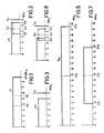
- FIG. 1 there is shown in idealised form the frequency characteristic of a wide band luminance information signal Y for a high definition television system.
- the bandwidth of the luminance information signal Y is 8.8 MHz which is over 3 MHz wider than that transmitted with colour television signals in the United Kingdom and most other countries and more than twice the bandwidth of the luminance information normally utilised in the majority of currently manufactured colour television receivers. It is considered that a bandwidth of 8.8 MHz is sufficient to give a marked improvement in the quality of a display obtained from the information and is sufficiently improved for it to be termed high definition in contrast with displays obtained with current television receivers.
- the choice of 8.8 MHz (nominal) for the bandwidth is by way of example only but such a frequency has advantages in the manufacture and operation of transmission and reception equipment as will become apparent from the description below of such equipment.
- the luminance information signal Y is considered to be divided into three regions which respectively comprise the lower frequency components Y L between 0 and 3.8 MHz, the middle frequency components Y m between 3.8 and 5.5 MHz and the upper frequency components Y u between 5.5 and 8.8 MHz.
- a colour television signal including a luminance information signal of the above bandwidth could not however be transmitted in the existing broadcast transmission channels of the U.H.F. bands IV and V in the United Kingdom or the appropriate broadcast transmission channels used elsewhere as such a signal would occupy a bandwidth greater than that allocated to such channels.
- the luminance information signal Y is effectively used to form two portions each of which may be transmitted within the bandwidth of the existing channels of the U.H.F. bands IV and V or other transmission channels or may be recorded within the bandwidth of most analogue video tape recorders.
- the first luminance portion contains the lower and middle frequency components, i.e. those up to 5.5 MHz, which is transmitted over a first transmission path such as a transmitted television channel or on a video tape recorder and the bandwidth of this first luminance portion is shown as Y1 in Figure 2.
- Figure 2 also shows that the colour information signal is transmitted with the first luminance portion.on a colour subcarrier f sc which is at the usual nominal frequency of 4.4 MHz, the modulation of the colour information extending above and below the subcarrier by approximately 1 MHz as per the system-I transmissions in the United Kingdom (see "Specification of television standards for 625-line system-I transmissions" published jointly by the British Broadcasting Corporation and the Independent Television Authority, January 1971, page 10, Figure 8).
- the colour information signal substantially lies between 3.5 and 5.5 MHz and is substantially contained within the spectrum occupied by the middle frequency components of the luminance information signal.
- the method of modulating the colour information would be as per that system but in countries using other systems such as N.T.S.C. or S.E.C.A.M. then the method of modulation would be as per those other systems.
- Figure 2 also shows that in the broadcast application a sound carrier f S1 is transmitted at 6 MHz in the normal manner which in the United Kingdom would be frequency modulated but in other countries this sound carrier would be at an appropriate different frequency such as 5.5 MHz.
- the second portion contains the middle and upper frequency components i.e.
- the transmission over the second path may also contain periodic bursts at the colour subcarrier frequency having the same phase as those which will be transmitted over the first transmission path and which may be used for synchronising purposes in a receiver as will be hereinafter explained.
- the transmission over the second transmission path does not however contain colour information modulation.
- the luminance portion Y2 shown in Figure 3 may be frequency inverted with respect to the portion contained above 3.8 MHz as shown in Figure 1.
- the advantage is obtained that both transmissions may be received together and the resulting portions of the luminance information added together, following the necessary processing, to reform the wide band luminance information.
- the middle frequency components between 3.8 and 5.5 MHz of the wide band luminance information signal is transmitted by both the first and second transmission paths whereas the colour information is transmitted by only the first transmission path. This can be used in a receiver to be described hereinafter whose display will be substantially free from cross-luminance and cross-colour interference.
- the system however, has a particular additional advantage in that it is compatible with current colour television transmissions in that one of the transmissions, namely that shown in Figure 2, may be received and displayed on a colour television of current manufacture and thus the'transmission of Figure 2 would produce a display of a quality corresponding to that currently produced by such receivers.
- the transmission of Figure 2 will also be fully used in more complex receivers which will embody means for cross-colour and cross-luminance reduction when utilising the full 5.5 MHz luminance infor ; mation when such receivers become available.
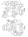
- Figure 4 shows a block diagram of television transmission equipment for use with the present transmission system.
- terminals 1, 2 and 3 respectively, receive red (R), green (G) and blue (B) colour signals such as those produced by a high definition colour television camera.
- R red
- G green
- B blue
- These colour signals are applied to a matrix circuit 4 which produces three outputs the first of which is a luminance signal Y' whilst the remaining two are respectively colour difference signals R-Y and B-Y.
- the colour difference signals R-Y and B-Y are applied through respective low-pass filters 5 and 6 of appropriate cut-off frequencies to a PAL encoder circuit 7 to which oscillations at the colour subcarrier frequency f sc (nominally 4.4 MHz) are applied from an oscillation generator 8, and this resulting colour subcarrier modulated by the colour difference signals is applied from an output of the PAL encoder circuit 7 together with the colour burst to the first input of an adder circuit 9.
- the luminance signal Y' from the matrix circuit 4 may have a bandwidth greater than 8.8 MHz and so this luminance signal is applied though a low pass filter 10 having a cut-off frequency of 8.8 MHz and the resulting signal is the wide band luminance information signal Y as shown in Figure 1.
- the signal Y is applied through a second low pass filter 11 which has a cut-off frequency of 5.5 MHz to produce the first portion of the luminance information signal Y1 comprising the lower and middle frequency components shown in Figure 2, this first portion being applied to the second input of the adder circuit 9.
- the other input of the adder circuit 9 receives line and field synchronising signals from a generator 12 and the output of the adder circuit 9 produces a composite television signal which includes the luminance and modulated colour information portions as shown in Figure 2, this being applied to a terminal 13 for transmission by way of a first transmission path.
- the wide band luminance information signal Y is also applied to a mixer circuit 14 which receives at a second input a signal of twice the frequency of the colour subcarrier, that is at a (nominal) frequency 8.8 MHz, from a frequency multiplier circuit 15 which itself receives a signal at the colour subcarrier frequency f sc from the oscillation generator 8.
- the mixer circuit 14 produces an 8.8 MHz carrier about which is modulated the wide band luminance information, the resulting signal Y m being shown in Figure 5 and from this Figure it will be appreciated that in the lower sideband frequency inversion has taken place.
- the modulated signal Y M is applied to a low pass filter 16 having a cut-off frequency of 5 MHz to produce at its output the signal Y2 shown in Figure 3 where the signal at zero frequency represents the luminance component at 8.8 MHz of the information shown in Figure 1 whilst that at 5 MHz represents the component at 3.8 MHz, this signal comprising the middle and upper frequency components of the luminance information signal Y.
- the output of the low pass filter 16 (to which the required d.c. component is added) is applied to a first input of a second adder circuit 17 a second input of which receives the line and field synchronising signals from the generator 12.
- a third input of the adder circuit 17 receives the colour burst of colour subcarrier frequency f sc from a second output of the PAL encoder circuit 7 in the same phase as that applied to adder circuit 9, for synchronisation purposes.
- the output of the adder circuit 17 is a composite television signal including the second luminance information portion Y2, this being applied to a terminal 18 for transmission by way of a second transmission path.
- Figure 6 shows an embodiment of television reception equipment for the reception of signals transmitted by the transmission equipment of Figure 4.
- the reception equipment of Figure 6 has two inputs 19 and 20 which respectively receive over separate transmission paths the signals respectively present at terminals 13 and 18.
- signals contain the burst at colour subcarrier frequency and this together with the line and field synchronising signals may be used to ensure accurate synchronisation between the two signals appearing at terminals 19 and 20. This may be achieved using known techniques and it is assumed that the signals at these terminals have such synchronisation.
- the signal received at terminal 20 is the signal of Figure 3 which is applied to a first input of a mixer circuit 21 a second input of which receives a signal 2f sc at twice the frequency of the subcarrier from a frequency multiplier circuit 22 which itself receives as its input the signal f sc from a subcarrier regenerative oscillator 23.
- the output of the mixer circuit 21 is the signal Y2 modulated on a carrier to twice the frequency of the subcarrier, this output being shown in Figure 7 from which it will be seen that the portion of the Y2 signal transmitted between 0 and 5 MHz is frequency converted to lie as a lower side-band between 3.8 MHz and 8.8 MHz and an upper side-band which lies between 8.8 MHz and 13.8 MHz.
- This signal is applied to a low pass filter 24 having a cut-off frequency at 8.8 MHz such that its output is the middle and higher frequency components of the wide band luminance Y namely those shown above 3.8 MHz in Figure 1.
- the output of mixer circuit 21 is also applied to a band-pass filter 25 having cut-off frequencies such that its output is the middle frequency components of the wide band signal i.e. those located between 3.8 and 5.5 MHz.
- This part of the output of the mixer circuit 21 corresponds to the middle frequency components present in the first portion Y1 of the luminance information signal which shares the same part of the frequency spectrum as the colour information signals when modulated on the colour subcarrier.
- the output from the band-pass filter 25 is applied to a first input of a subtractor circuit 26 a second input of which receives the signal of Figure 2 present at terminal 19.
- the output of this subtractor circuit 26 consists of a signal in which the luminance and colour information signals are substantially separated in frequency, those components of the spectrum between 0 and 3.5 MHz being substantially luminance only whilst those between 3.8 and 5.5 MHz are substantially colour information only as shown in Figure 8 with a small overlap between 3.5 and 3.8 MHz.
- the output from the subtractor circuit 26 is applied to a low pass filter 27 having a cut-off frequency of 3.8 MHz such that its output contains the low frequency components of the luminance information signal which components are applied to a first input of an adding circuit 28.
- the output of subtractor circuit 26 is also applied to a band-pass filter 29 having a passband between the frequencies 3.5 and 5.5 MHz and which thus produces at its output the modulated colour subcarrier which is applied to a first input of a PAL decoder circuit 30.
- This signal from filter 29 is also applied to the subcarrier regenerative oscillator 23 which produces oscillations at the subcarrier frequency f sc for application to a second input of the PAL decoder circuit 30.
- the PAL decoder circuit produces two outputs which respectively convey the colour difference signals R-Y and B-Y which signals are applied to respective first and second inputs of a matrix circuit 31.
- the input at terminal 19 is also applied to a sync. separator circuit 32 which produces separated line (H) and field (V) synchronising signals which are shown applied to terminals 33 and 34 for use in the production of the display in the usual manner.
- the output from the band-pass filter 24 is applied to a second input of the adder 28 the output of which is the reconstituted wide band luminance information signal Y of Figure 1 and which is applied to a third input of the matrix circuit 31.
- the matrix circuit operates on the wide band luminance information Y and the colour difference signals R-Y and B-Y to produce at respective output terminals 35, 36, and 37 colour signals R, G and B. These colour signals may then be applied to a high definition display tube to produce a high quality colour television display.
Landscapes
- Engineering & Computer Science (AREA)
- Multimedia (AREA)
- Signal Processing (AREA)
- Color Television Systems (AREA)
Claims (12)
Applications Claiming Priority (2)
| Application Number | Priority Date | Filing Date | Title |
|---|---|---|---|
| GB8217099 | 1982-06-11 | ||
| GB08217099A GB2122836A (en) | 1982-06-11 | 1982-06-11 | Television transmission system |
Publications (3)
| Publication Number | Publication Date |
|---|---|
| EP0096921A2 EP0096921A2 (fr) | 1983-12-28 |
| EP0096921A3 EP0096921A3 (en) | 1984-02-22 |
| EP0096921B1 true EP0096921B1 (fr) | 1986-03-12 |
Family
ID=10530995
Family Applications (1)
| Application Number | Title | Priority Date | Filing Date |
|---|---|---|---|
| EP83200798A Expired EP0096921B1 (fr) | 1982-06-11 | 1983-06-03 | Système de transmission de télévision |
Country Status (5)
| Country | Link |
|---|---|
| US (1) | US4520385A (fr) |
| EP (1) | EP0096921B1 (fr) |
| JP (1) | JPS594287A (fr) |
| DE (1) | DE3362527D1 (fr) |
| GB (1) | GB2122836A (fr) |
Families Citing this family (12)
| Publication number | Priority date | Publication date | Assignee | Title |
|---|---|---|---|---|
| IT1151901B (it) * | 1982-07-07 | 1986-12-24 | Rai Radiotelevisione Italiana | Sistema di trasmissione e di ricezione di segnali televisivi a colori su due canali per la radiodiffusione da satellite ed impianto per l'attuazione del sistema |
| GB2138238B (en) * | 1983-03-02 | 1987-07-08 | British Broadcasting Corp | High definition video signal transmission |
| JPS59171387A (ja) * | 1983-03-18 | 1984-09-27 | Hitachi Ltd | テレビジヨン信号の構成方法 |
| JPS6068793A (ja) * | 1983-09-26 | 1985-04-19 | Sony Corp | カラ−ビデオ信号のデイジタル化回路 |
| US4589011A (en) * | 1984-01-16 | 1986-05-13 | At&T Bell Laboratories | Single sideband modulated chrominance information for compatible high-definition television |
| US4613903A (en) * | 1984-04-06 | 1986-09-23 | North American Philips Corporation | High-resolution television transmission system |
| US4694338A (en) * | 1986-04-25 | 1987-09-15 | North American Philips Corporation | High-definition television transmission system |
| JPS63108888A (ja) * | 1986-10-27 | 1988-05-13 | Canon Inc | カラ−ビデオ信号再生装置 |
| US4965661A (en) * | 1988-08-04 | 1990-10-23 | Scientific-Atlanta, Inc. | Method and apparatus for increasing the definiton of an NTSC video signal using an augmentation channel |
| US4989091A (en) * | 1988-11-16 | 1991-01-29 | Scientific-Atlanta, Inc. | Scan converter for a high definition television system |
| US5031030A (en) * | 1990-08-20 | 1991-07-09 | General Electric Company | Video signal encoded with additional detail information |
| US5606423A (en) * | 1990-10-18 | 1997-02-25 | Samsung Electronics Co., Ltd. | Compatible high-resolution video recording format |
Family Cites Families (5)
| Publication number | Priority date | Publication date | Assignee | Title |
|---|---|---|---|---|
| US4003077A (en) * | 1976-02-25 | 1977-01-11 | Eastman Kodak Company | Method and apparatus for cancelling chrominance artifacts |
| DE2908321C2 (de) * | 1979-03-03 | 1984-06-28 | Robert Bosch Gmbh, 7000 Stuttgart | Verfahren und Schaltungsanordnung zum Übertragen oder Speichern eines breitbandigen kontinuierlichen Signals in mehreren schmalbandigen Kanälen |
| GB2075790A (en) * | 1980-05-06 | 1981-11-18 | Philips Electronic Associated | Colour television transmission |
| JPS5799887A (en) * | 1980-12-12 | 1982-06-21 | Victor Co Of Japan Ltd | Recording and reproducing system for pal color video signal and its recording medium |
| US4435734A (en) * | 1981-11-12 | 1984-03-06 | Vas Corporation | FM Video recording and reproducing system |
-
1982
- 1982-06-11 GB GB08217099A patent/GB2122836A/en not_active Withdrawn
- 1982-12-06 US US06/447,083 patent/US4520385A/en not_active Expired - Fee Related
-
1983
- 1983-06-03 EP EP83200798A patent/EP0096921B1/fr not_active Expired
- 1983-06-03 DE DE8383200798T patent/DE3362527D1/de not_active Expired
- 1983-06-10 JP JP58103000A patent/JPS594287A/ja active Pending
Also Published As
| Publication number | Publication date |
|---|---|
| GB2122836A (en) | 1984-01-18 |
| EP0096921A3 (en) | 1984-02-22 |
| EP0096921A2 (fr) | 1983-12-28 |
| JPS594287A (ja) | 1984-01-11 |
| DE3362527D1 (en) | 1986-04-17 |
| US4520385A (en) | 1985-05-28 |
Similar Documents
| Publication | Publication Date | Title |
|---|---|---|
| EP0120390B1 (fr) | Système de transmission de signaux de télévision | |
| KR860001201B1 (ko) | 고 선명도 칼라 텔레비젼과 종래 칼라 텔레비젼간의 양립성 제공 장치 | |
| US4944032A (en) | Multiplex signal processing apparatus | |
| KR100188832B1 (ko) | 텔레비젼 신호에 보조정보를 전송하는 장치 | |
| US4567508A (en) | Two-channel compatible television transmission system for wide picture formats | |
| EP0070154B1 (fr) | Systèmes de télévision en couleurs | |
| EP0113932B1 (fr) | Système de transmission de télévision | |
| US4510520A (en) | Television transmission system | |
| US4520385A (en) | Television transmission system | |
| US4745460A (en) | Method for transmitting a television signal by field to field processing | |
| US4051517A (en) | Hybrid sequential and carrier encoded color television transmission method and circuits | |
| US2828354A (en) | Colour-television transmission systems | |
| US3921203A (en) | Trisequential color video record-playback method and circuits | |
| US3742127A (en) | Method for recording a pal color television signal | |
| JPS62206992A (ja) | テレビジヨン信号合成装置 | |
| GB2145610A (en) | Television transmission systems | |
| US3969761A (en) | Transmitter and receiver circuits for the sequential storage color television system | |
| US4472746A (en) | Chrominance channel bandwidth modification system | |
| US2832817A (en) | Intelligence transmission system | |
| GB2075790A (en) | Colour television transmission | |
| KR950000827B1 (ko) | 휘도신호의 다중화를 위한 Tci 방식의 HD-TV용 변복조방법 | |
| GB2112245A (en) | Colour television systems | |
| Holoch et al. | Improved PAL by a Combination of NTSC-SECAM-PAL | |
| JPS647555B2 (fr) | ||
| JPS63263987A (ja) | カラ−映像信号伝送方法 |
Legal Events
| Date | Code | Title | Description |
|---|---|---|---|
| PUAI | Public reference made under article 153(3) epc to a published international application that has entered the european phase |
Free format text: ORIGINAL CODE: 0009012 |
|
| PUAL | Search report despatched |
Free format text: ORIGINAL CODE: 0009013 |
|
| AK | Designated contracting states |
Designated state(s): DE FR GB |
|
| AK | Designated contracting states |
Designated state(s): DE FR GB |
|
| 17P | Request for examination filed |
Effective date: 19840314 |
|
| GRAA | (expected) grant |
Free format text: ORIGINAL CODE: 0009210 |
|
| AK | Designated contracting states |
Kind code of ref document: B1 Designated state(s): DE FR GB |
|
| REF | Corresponds to: |
Ref document number: 3362527 Country of ref document: DE Date of ref document: 19860417 |
|
| ET | Fr: translation filed | ||
| PLBE | No opposition filed within time limit |
Free format text: ORIGINAL CODE: 0009261 |
|
| STAA | Information on the status of an ep patent application or granted ep patent |
Free format text: STATUS: NO OPPOSITION FILED WITHIN TIME LIMIT |
|
| 26N | No opposition filed | ||
| PGFP | Annual fee paid to national office [announced via postgrant information from national office to epo] |
Ref country code: FR Payment date: 19910621 Year of fee payment: 9 |
|
| PGFP | Annual fee paid to national office [announced via postgrant information from national office to epo] |
Ref country code: DE Payment date: 19910823 Year of fee payment: 9 |
|
| PGFP | Annual fee paid to national office [announced via postgrant information from national office to epo] |
Ref country code: GB Payment date: 19920508 Year of fee payment: 10 |
|
| PG25 | Lapsed in a contracting state [announced via postgrant information from national office to epo] |
Ref country code: FR Effective date: 19930226 |
|
| PG25 | Lapsed in a contracting state [announced via postgrant information from national office to epo] |
Ref country code: DE Effective date: 19930302 |
|
| REG | Reference to a national code |
Ref country code: FR Ref legal event code: ST |
|
| PG25 | Lapsed in a contracting state [announced via postgrant information from national office to epo] |
Ref country code: GB Effective date: 19930603 |
|
| GBPC | Gb: european patent ceased through non-payment of renewal fee |
Effective date: 19930603 |