EP0096923B1 - Steinfangmulde für Mähdrescher - Google Patents
Steinfangmulde für Mähdrescher Download PDFInfo
- Publication number
- EP0096923B1 EP0096923B1 EP83200803A EP83200803A EP0096923B1 EP 0096923 B1 EP0096923 B1 EP 0096923B1 EP 83200803 A EP83200803 A EP 83200803A EP 83200803 A EP83200803 A EP 83200803A EP 0096923 B1 EP0096923 B1 EP 0096923B1
- Authority
- EP
- European Patent Office
- Prior art keywords
- stone trap
- pivot
- combine harvester
- trap
- harvester according
- Prior art date
- Legal status (The legal status is an assumption and is not a legal conclusion. Google has not performed a legal analysis and makes no representation as to the accuracy of the status listed.)
- Expired
Links
- 239000004575 stone Substances 0.000 title claims description 110
- 241001124569 Lycaenidae Species 0.000 title description 3
- 239000000463 material Substances 0.000 claims description 11
- 230000007704 transition Effects 0.000 claims description 7
- 230000000717 retained effect Effects 0.000 claims description 3
- 238000000034 method Methods 0.000 claims description 2
- 238000007789 sealing Methods 0.000 claims 2
- 238000004140 cleaning Methods 0.000 description 5
- 230000009193 crawling Effects 0.000 description 2
- 230000000694 effects Effects 0.000 description 2
- 241001272996 Polyphylla fullo Species 0.000 description 1
- 240000008042 Zea mays Species 0.000 description 1
- 235000005824 Zea mays ssp. parviglumis Nutrition 0.000 description 1
- 235000002017 Zea mays subsp mays Nutrition 0.000 description 1
- 230000005540 biological transmission Effects 0.000 description 1
- 238000010276 construction Methods 0.000 description 1
- 235000005822 corn Nutrition 0.000 description 1
- 238000003306 harvesting Methods 0.000 description 1
- 239000002184 metal Substances 0.000 description 1
- 239000011435 rock Substances 0.000 description 1
- 239000010902 straw Substances 0.000 description 1
Images


Classifications
-
- A—HUMAN NECESSITIES
- A01—AGRICULTURE; FORESTRY; ANIMAL HUSBANDRY; HUNTING; TRAPPING; FISHING
- A01F—PROCESSING OF HARVESTED PRODUCE; HAY OR STRAW PRESSES; DEVICES FOR STORING AGRICULTURAL OR HORTICULTURAL PRODUCE
- A01F12/00—Parts or details of threshing apparatus
- A01F12/10—Feeders
- A01F12/16—Safety devices
Definitions
- This invention relates to combine harvesters fitted with so-called stone traps which are arranged to receive and retain therein not only stones and rocks but any other hard object which might be entrained in the crop material fed to the threshing mechanism and which would damage the latter if allowed to reach the same.
- the ideal position for a stone trap is between the threshing mechanism and the normal crop elevator which feeds crop material to the threshing mechanism from the crop pick-up device.
- the stone trap thus lies at the transition between the crop elevator and the threshing mechanism but below the plane of that transition which means that it obscures the concave of the threshing mechanism and the grain pan which is disposed beneath the latter, as seen from the front of the machine.
- a stone trap is disposed in the usual position and has a door which, when opened, allows easy emptying or cleaning of the stone trap.
- the stone trap is oriented such that when the door is open, access is provided to the transition area between the crop elevator and the threshing mechanism for clearing any blockage therein which may occur. However, no access is provided to the concave mechanism and/or the grain pan.
- British Specification No. 1,345,846 discloses a combined harvester having a stone trap which is removable from the front of the machine thus providing access to the concave and grain pan.
- a handling problem arises with this arrangement in that the stone trap is relatively heavy when empty due to its all-metal construction and is, therefore, much heavier when full to the extent that it is not easy to handle unless the operator is in a good position.
- the operator has to stoop or kneel beneath the crop elevator (which is moved to its raised position for this operation), reach upwardly to release the latches retaining the stone trap in position, and then lower the trap as well as withdrawing it forwardly of the machine.
- the operator is not ideally positioned for removal or replacement of the stone trap, particularly when having to bear the weight of a full trap on initial release of the latches and lowering of the trap.
- a combine harvester comprises a crop elevator, a threshing mechanism including a threshing concave to which, in use, the crop elevator feeds crop material, a grain pan underneath the concave and a stone trap located between the crop elevator and the threshing mechanism and having an inlet disposed generally at the transition therebetween; said stone trap being removable from the combine harvester to enable access to the underside of the threshing concave and/or to the grain pan and being supported, in the operative position, by first releasable pivot means and being retained, in said operative position, by latch means; the arrangement being such that, on release of the latch means, initially the stone trap can pivot forwardly of the machine about the first pivot means whilst still being supported thereby and subsequently the first pivot means can disengage for final removal of the stone trap from the machine.
- the first pivot means are located such that the stone trap moves generally downwardly as well as forwardly about the first pivot means on release of the latch means.
- the first pivot means are located both rearwardly and below the stone trap and also below the grain pan, disposed underneath the threshing mechanism and rearwardly of the front edge thereof.
- the first pivot means comprise two first pivot pins spaced apart transversely of the machine and being releasably cooperable with bearing means which respectively locate the pivot pins whilst permitting rotation thereof.
- Each first pivot pin is carried on one end of a first arm, the distal end of which is attached to the stone trap via bearing means which receive a second pivot pin, with the first arm connected, via the bearing means, to a second arm.
- Each second arm is engageable with the stone trap after a predetermined pivotal movement of the latter about the axis of the second pivot pins so as thereafter to rotate with the stone trap and hence rotate the associated first arms to disengage the first pivot pins from their bearing surfaces.
- Abutment means are provided on the stone trap to engage the respective first arms on return pivotal movement of the stone trap so as to rotate those arms and re-engage the first pivot pins with their bearing means.
- Second pivot means may be provided which are operable pivotably to support the stone trap only when the latter is being moved to or from the operative position.
- the second pivot means comprise two third pivot pins and associated bearing means spaced transversely of the machine with the bearing means attached to the frame of the machine and disposed below the stone trap and spaced from the associated third pivot pin when the stone trap is in the operative position.
- the third pivot pins engage the respective bearing means on downward movement of the stone trap so as to assist in the support of the latter, the arrangement being such that when the stone trap is removed from the machine it is first supported by, and pivoted about, the first pivot means and also moves downwardly so as to engage the second pivot means about which further pivotal movement is effected, whereby the first pivot means are disengaged.
- Final removal of the stone trap is effected by disengaging the second pivot means, the removal procedure being reversed on replacement of the stone trap.
- the combine harvester is generally conventional and comprises a header 1 embodying a reel 2, a cutterbar 3, an auger 4 which consolidates cut crop centrally of the machine and feeds it to a crop elevator 5 which comprises a chain conveyor having crop conveying elements 6 attached to the links 7 thereof, one link and conveying element being shown in Figure 2.
- the header 1 is pivotally mounted at 8 on the chassis or frame of the machine and is raised or lowered about this pivot by a hydraulic ram 9.
- the machine further comprises a threshing mechanism 11, having a rotor 12 and a concave 13, a separating mechanism 14, straw walkers 15, a grain pan 16, and a cleaning mechanism 17 which receives grain from the grain pan. Clean grain is taken to a grain tank 18 by a grain elevator 19.
- the machine has a pair of driven front wheels 21, and a pair of rear, steerable wheels 22, the operator controlling the machine from a platform 23.
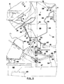
- a stone trap 24 is provided between the crop elevator 5 and the threshing mechanism 11 and will now be described in detail with particular reference to Figures 2 and 3.
- the stone trap comprises a basic container having a base 25, a rear wall 26, a front wall 27, and two side walls 28.
- the front wall 27 is pivotally attached to the base 25 at 29, whereby it forms a door which can be swung open forwardly of the machine to permit emptying of the trap.
- a pair of handles 31 is attached to the door 27 and a pair of releasable latches 32 retain the door in the closed position.
- a flexible strip 33 is secured along the top edge of the door 27 and cooperates with the underside of a floor 34 of the crop elevator 5 to provide a seal between that floor and the front of the stone trap.
- the base 25 of the stone trap has a rearwardly and upwardly extending portion which facilitates emptying, and the rear wall 26 has an upper extension 35 which is profiled to present a surface 36 which assists in the smooth flow of crop material from the crop elevator 5 to the threshing mechanism 11, part of the latter being shown in Figure 2 by way of a rasp bar 37 of the rotor 12 (the rasp bars describing a circle indicated at 38), and the forward end of the concave 13 to which is attached a member 39 also presenting a surface 41 which assists in the flow of crop material to the threshing mechanism.
- the surfaces 36 and 41 are in general alignment although some offset will occur depending on the spacing of the concave 13 from the rotor 12, which spacing is adjustable, with Figure 2 showing the concave in the position in which it is closest to the rotor.
- the top of the stone trap container is open, thus providing an inlet 40 for the stones and other foreign objects, the inlet being generally in the plane of the transition between the crop elevator 5 and the threshing mechanism 11 so that stones, etc. can fall into the stone trap as crop material passes thereover, the rasp bar 37 also serving to propel the stones, etc. into the stone trap as they contact crop material in the general area indicated at 42.
- the stone trap 24 further comprises a downwardly-extending panel 43 attached to the underside of the base 25 and formed with a flange 44 at each end, the flanges lying adjacent respective upright beams 45 of the frame of the machine, other frame components indicated in Figures 2 and 3 being a transverse beam 46 interconnecting the beams 45, longitudinal beams 47 to which the respective beams 45 are connected, and a further transverse beam 48.
- Mounted on the panel 43 adjacent each flange 44 is a releasable latch 49 comprising a springloaded bolt 51 having a handle 52 attached to one end with the other end being engageable with aligned apertures in the associated flange 44 and beam 45.
- the two latches 49 serve to retain the stone trap in the operative position but can be released to enable removal of the stone trap when desired.
- each pivot means 53 is offset inwardly of the adjacent stone trap sidewall 28 and comprises a pivot bearing in the form of a pair of spaced arms 54 extending upwardly and slightly forwardly from the transverse beam 46 and each having a generally V-shaped bearing surface 55 formed in its upper end.
- a pivot pin or rod 56 engages the bearing surfaces 55 of respective pairs of arms 54 and is rotatable relative thereto, the pivot pin being carried on one end of an arm 57 the distal end of which is rigidly attached to a shorter arm. 58 via a bush 59.
- the arms 57 and 58 define an obtuse angle and each arm 57 is located between the associated pairs of arms 54.
- a pivot pin 61 extends through the bush 59 and through further bushes 62 formed on the lower edge of the panel 43 on either side of the bush 59.
- Abutment members 60 ( Figure 2) are fixed to the panel 43 adjacent respective arms 57, each member being engageable with the associated arm.
- a further pivot pin or rod 63 is provided on the lower edge of the panel 43 adjacent each side thereof, these pivot pins not being functional whilst the stone trap is in the operative position as shown in full lines in Figure 2.
- the pivot pins 63 are capable of being received by respective pivot bearings or bushes 64 disposed therebelow as seen in Figures 2 and 3 (full lines) and attached to respective upright beams 45, the bearings being generally semicircular as seen in side view so as to be able to receive and relinquish the pivot pins, the diametral plane of the open end of each bearing being inclined upwardly and rearwardly of the machine.
- FIG 2 shows the front end of the grain pan 16 which, as is conventional, is reciprocated in use of the machine so as to shake the grain falling thereon from the concave 13 to the rear end of the pan from where it falls to the sieves of the cleaning mechanism 17.
- a flexible seal or boot 65 extends between the grain pan and a member 66 so as to allow relative movement between the two components whilst maintaining a seal to prevent grain falling from the front edge of the grain pan.
- a further seal 67 is fitted to the top edge of the member 66 and extends forwardly for engagement by the rear of the panel 43.
- a gear box 68 which is provided on the axle of the front driven wheels 21 and provides the power to drive the front wheels, the gear box being connected to the engine of the machine by a drive transmission (not shown).
- the stone trap 24 In use of the machine, the stone trap 24 is in the operative (full line) position of Figure 2 and stones and other objects are received therein through the inlet 40 from the crop material which passes from the crop elevator 5 to the threshing mechanism 11.
- the header 1 When the stone trap needs to be emptied, the header 1 is raised to the chain dotted line position of Figure 2, thereby allowing the operator to approach the front of the stone trap 24. He then releases the latches 32 and opens the door 27 by grasping the handles 31 and pivoting the door downwardly about the pivot 29, thereby exposing the interior of the trap.
- the stone trap When emptied, the stone trap is rendered operative again by closing the door 27 and reactivating the latches 32, the header 1 then being lowered to the desired working height.
- the stone trap 24 With the stone trap 24 removed, the operator now has ready access to the concave 13 and grain pan 16 as well as the transition area between the crop elevator 5 and the threshing mechanism 11.
- the stone trap is replaced by first orienting it in the general position shown by the chain dotted lines of Figure 2 and engaging the pivot pins 63 in the respective pivot bearings 64. The operator then raises the stone trap about the axes of the pivot pins 63 and the pivot pins 61, whereupon at a certain point the panel 43 will disengage the arms 58 but the abutment members 60 will re-engage the arms 57 and thus rotate them clockwise (as seen in Figure 2) until the pivot pins 56 engage the respective bearing surfaces 55.
- the stone trap is in the broken line position of Figure 2, and the final replacement operation is to lift the stone trap further and pivot it about the axis of the pivot pins 56, whereby the pivot pins 63 disengage the pivot bearings 64, the operator manipulating the bolts 51 using the handles 52 so as to re-engage the bolts in the respective apertures in the flanges 44 and upright beams 45 to lock the stone trap in the operative position.
Landscapes
- Life Sciences & Earth Sciences (AREA)
- Environmental Sciences (AREA)
- Harvester Elements (AREA)
Claims (15)
Applications Claiming Priority (2)
| Application Number | Priority Date | Filing Date | Title |
|---|---|---|---|
| GB8217278 | 1982-06-15 | ||
| GB8217278 | 1982-06-15 |
Publications (2)
| Publication Number | Publication Date |
|---|---|
| EP0096923A1 EP0096923A1 (de) | 1983-12-28 |
| EP0096923B1 true EP0096923B1 (de) | 1986-12-30 |
Family
ID=10531041
Family Applications (1)
| Application Number | Title | Priority Date | Filing Date |
|---|---|---|---|
| EP83200803A Expired EP0096923B1 (de) | 1982-06-15 | 1983-06-03 | Steinfangmulde für Mähdrescher |
Country Status (4)
| Country | Link |
|---|---|
| US (1) | US4446875A (de) |
| EP (1) | EP0096923B1 (de) |
| CA (1) | CA1211020A (de) |
| DE (1) | DE3368487D1 (de) |
Cited By (5)
| Publication number | Priority date | Publication date | Assignee | Title |
|---|---|---|---|---|
| EP0516892A1 (de) * | 1991-06-04 | 1992-12-09 | New Holland Belgium N.V. | Steinauffangvorrichtung für Mähdrescher |
| EP0516890A1 (de) * | 1991-06-04 | 1992-12-09 | New Holland Belgium N.V. | Getreide- und Spreuelevator für Mähdrescher |
| EP0516891A1 (de) * | 1991-06-04 | 1992-12-09 | New Holland Belgium N.V. | Schwenkbarer Elevator für Getreide und Spreu |
| EP0516893A1 (de) * | 1991-06-04 | 1992-12-09 | New Holland Belgium N.V. | Zugang zur Dreschanlage eines Mähdreschers |
| EP0532072A1 (de) * | 1991-08-30 | 1993-03-17 | New Holland Belgium N.V. | Steinfangmulde für Mähdrescher |
Families Citing this family (8)
| Publication number | Priority date | Publication date | Assignee | Title |
|---|---|---|---|---|
| DE3905968C1 (de) * | 1989-02-25 | 1990-02-22 | Deere & Co., Moline, Ill., Us, Niederlassung Deere & Co. European Office, 6800 Mannheim, De | |
| US5395287A (en) * | 1993-05-10 | 1995-03-07 | Deere & Company | Multi-profile transition element |
| US5702300A (en) * | 1996-04-18 | 1997-12-30 | Agco Corporation | Combine rock door over center closure apparatus |
| CA2241609C (en) * | 1997-06-26 | 2009-08-25 | Southpac Trust International, Inc. | Polymeric material having a cloth-like appearance |
| DE10353339A1 (de) | 2003-11-14 | 2005-06-02 | Deere & Company, Moline | Mähdrescher mit Steinfalle |
| BE1022519B1 (nl) * | 2014-10-20 | 2016-05-19 | Cnh Industrial Belgium Nv | Steenvangergeheel voor een oogstmachine |
| US10405492B2 (en) | 2017-06-19 | 2019-09-10 | Cnh Industrial America Llc | Self-cleaning rock sump for an agricultural harvester and related systems and methods |
| DE102021109629A1 (de) * | 2021-04-16 | 2022-10-20 | Maschinenfabrik Bernard Krone GmbH & Co. KG | Rundballenpresse mit Starterwalze und elastisch auslenkbarem Auslenkelement |
Family Cites Families (6)
| Publication number | Priority date | Publication date | Assignee | Title |
|---|---|---|---|---|
| DE2013289B1 (de) * | 1970-03-20 | 1971-04-22 | ||
| DE2024706A1 (de) * | 1970-05-21 | 1971-12-23 | Maschinenfabrik Fahr Ag, 7702 Gottmadingen | Steinauffangvorrichtung für Erntemaschinen, insbesondere Mähdrescher |
| DE2122402C3 (de) * | 1971-05-06 | 1973-12-20 | Gebr. Claas Maschinenfabrik Gmbh, 4834 Harsewinkel | Steinfangmulde für Mähdrescher |
| US3913589A (en) * | 1973-02-08 | 1975-10-21 | Int Harvester Co | Grain pan bottom door |
| US3971390A (en) * | 1974-06-03 | 1976-07-27 | Sperry Rand Corporation | Stone trap for threshing and separating machine |
| DD116736A1 (de) * | 1975-01-20 | 1975-12-12 | Sonja Noltemeier | Steinfangmulde fuer maehdrescher |
-
1983
- 1983-06-03 DE DE8383200803T patent/DE3368487D1/de not_active Expired
- 1983-06-03 EP EP83200803A patent/EP0096923B1/de not_active Expired
- 1983-06-09 US US06/502,854 patent/US4446875A/en not_active Expired - Lifetime
- 1983-06-14 CA CA000430369A patent/CA1211020A/en not_active Expired
Cited By (5)
| Publication number | Priority date | Publication date | Assignee | Title |
|---|---|---|---|---|
| EP0516892A1 (de) * | 1991-06-04 | 1992-12-09 | New Holland Belgium N.V. | Steinauffangvorrichtung für Mähdrescher |
| EP0516890A1 (de) * | 1991-06-04 | 1992-12-09 | New Holland Belgium N.V. | Getreide- und Spreuelevator für Mähdrescher |
| EP0516891A1 (de) * | 1991-06-04 | 1992-12-09 | New Holland Belgium N.V. | Schwenkbarer Elevator für Getreide und Spreu |
| EP0516893A1 (de) * | 1991-06-04 | 1992-12-09 | New Holland Belgium N.V. | Zugang zur Dreschanlage eines Mähdreschers |
| EP0532072A1 (de) * | 1991-08-30 | 1993-03-17 | New Holland Belgium N.V. | Steinfangmulde für Mähdrescher |
Also Published As
| Publication number | Publication date |
|---|---|
| DE3368487D1 (en) | 1987-02-05 |
| EP0096923A1 (de) | 1983-12-28 |
| CA1211020A (en) | 1986-09-09 |
| US4446875A (en) | 1984-05-08 |
Similar Documents
| Publication | Publication Date | Title |
|---|---|---|
| EP1576868B1 (de) | Korntank einer Erntemaschine | |
| EP0096923B1 (de) | Steinfangmulde für Mähdrescher | |
| US4709541A (en) | Grass/lawn debris handling system | |
| EP1074175B1 (de) | Verteiler für von einem Mähdrescher ausgeworfene Erntegutreste | |
| JP5508619B2 (ja) | コンバイン | |
| EP0532072B1 (de) | Steinfangmulde für Mähdrescher | |
| CA1089240A (en) | Pea harvesters | |
| CS221502B2 (en) | Reaping machine | |
| DE3006871A1 (de) | Selbstfahrender maehdrescher | |
| EP1120027B1 (de) | Turmsystem für Förderschnecke eines Mähdreschers | |
| US5695399A (en) | Foldable loading auger having a gas spring | |
| US3135080A (en) | Forage harvesting units | |
| EP0468362B1 (de) | Vorrichtung zum seitlichen Anschliessen eines Sammelbehälters an ein Fahrzeug | |
| EP4494440A1 (de) | Hebesystem für eine befüllschnecke eines mähdreschers | |
| CA2448605C (en) | Grain compartment cleanout arrangement | |
| CA2448952C (en) | Closure for a cleanout opening of a harvesting apparatus | |
| JPH0233649Y2 (de) | ||
| US3304698A (en) | Three-point hitch mounted crop gathering and treating apparatus | |
| EP1530895B1 (de) | Mähdrescher mit Steinfalle | |
| JPH05153836A (ja) | さとうきび収穫機 | |
| JPH0739389Y2 (ja) | 普通形コンバイン | |
| JPH036172Y2 (de) | ||
| JPS6041078Y2 (ja) | モアにおける刈草放出装置 | |
| CA1250748A (en) | Grass/lawn debris handling system | |
| JPH0233472Y2 (de) |
Legal Events
| Date | Code | Title | Description |
|---|---|---|---|
| PUAI | Public reference made under article 153(3) epc to a published international application that has entered the european phase |
Free format text: ORIGINAL CODE: 0009012 |
|
| 17P | Request for examination filed |
Effective date: 19830603 |
|
| AK | Designated contracting states |
Designated state(s): DE FR GB |
|
| GRAA | (expected) grant |
Free format text: ORIGINAL CODE: 0009210 |
|
| AK | Designated contracting states |
Kind code of ref document: B1 Designated state(s): DE FR GB |
|
| RAP2 | Party data changed (patent owner data changed or rights of a patent transferred) |
Owner name: NEW HOLLAND N.V. |
|
| REF | Corresponds to: |
Ref document number: 3368487 Country of ref document: DE Date of ref document: 19870205 |
|
| ET | Fr: translation filed | ||
| PLBE | No opposition filed within time limit |
Free format text: ORIGINAL CODE: 0009261 |
|
| STAA | Information on the status of an ep patent application or granted ep patent |
Free format text: STATUS: NO OPPOSITION FILED WITHIN TIME LIMIT |
|
| 26N | No opposition filed | ||
| PGFP | Annual fee paid to national office [announced via postgrant information from national office to epo] |
Ref country code: FR Payment date: 19930427 Year of fee payment: 11 |
|
| PGFP | Annual fee paid to national office [announced via postgrant information from national office to epo] |
Ref country code: DE Payment date: 19930429 Year of fee payment: 11 |
|
| PGFP | Annual fee paid to national office [announced via postgrant information from national office to epo] |
Ref country code: GB Payment date: 19930521 Year of fee payment: 11 |
|
| PG25 | Lapsed in a contracting state [announced via postgrant information from national office to epo] |
Ref country code: GB Effective date: 19940603 |
|
| GBPC | Gb: european patent ceased through non-payment of renewal fee |
Effective date: 19940603 |
|
| PG25 | Lapsed in a contracting state [announced via postgrant information from national office to epo] |
Ref country code: FR Effective date: 19950228 |
|
| PG25 | Lapsed in a contracting state [announced via postgrant information from national office to epo] |
Ref country code: DE Effective date: 19950301 |
|
| REG | Reference to a national code |
Ref country code: FR Ref legal event code: ST |