EP0096958A1 - Verfahren und Gerät zur Reparatur von Drains und unterirdisch verlegten Rohren - Google Patents
Verfahren und Gerät zur Reparatur von Drains und unterirdisch verlegten Rohren Download PDFInfo
- Publication number
- EP0096958A1 EP0096958A1 EP83302375A EP83302375A EP0096958A1 EP 0096958 A1 EP0096958 A1 EP 0096958A1 EP 83302375 A EP83302375 A EP 83302375A EP 83302375 A EP83302375 A EP 83302375A EP 0096958 A1 EP0096958 A1 EP 0096958A1
- Authority
- EP
- European Patent Office
- Prior art keywords
- drain
- pipeline
- defect
- ejector
- ejector body
- Prior art date
- Legal status (The legal status is an assumption and is not a legal conclusion. Google has not performed a legal analysis and makes no representation as to the accuracy of the status listed.)
- Granted
Links
- 238000000034 method Methods 0.000 title claims abstract description 16
- 230000007547 defect Effects 0.000 claims abstract description 38
- 150000001875 compounds Chemical class 0.000 claims abstract description 19
- 238000007789 sealing Methods 0.000 claims abstract description 15
- 230000001427 coherent effect Effects 0.000 claims abstract description 4
- 230000008439 repair process Effects 0.000 claims description 24
- 239000012530 fluid Substances 0.000 claims description 6
- 238000006073 displacement reaction Methods 0.000 claims description 2
- 239000000463 material Substances 0.000 description 7
- 239000000203 mixture Substances 0.000 description 6
- 239000007788 liquid Substances 0.000 description 5
- 238000007689 inspection Methods 0.000 description 4
- 238000010276 construction Methods 0.000 description 3
- 239000004848 polyfunctional curative Substances 0.000 description 3
- 230000002950 deficient Effects 0.000 description 2
- 238000005498 polishing Methods 0.000 description 2
- 239000004576 sand Substances 0.000 description 2
- 239000007787 solid Substances 0.000 description 2
- XLYOFNOQVPJJNP-UHFFFAOYSA-N water Substances O XLYOFNOQVPJJNP-UHFFFAOYSA-N 0.000 description 2
- 208000031872 Body Remains Diseases 0.000 description 1
- 235000012206 bottled water Nutrition 0.000 description 1
- 238000004140 cleaning Methods 0.000 description 1
- 230000000295 complement effect Effects 0.000 description 1
- 230000008878 coupling Effects 0.000 description 1
- 238000010168 coupling process Methods 0.000 description 1
- 238000005859 coupling reaction Methods 0.000 description 1
- 239000003651 drinking water Substances 0.000 description 1
- 239000003822 epoxy resin Substances 0.000 description 1
- 239000000835 fiber Substances 0.000 description 1
- 239000007789 gas Substances 0.000 description 1
- 239000011440 grout Substances 0.000 description 1
- 238000011065 in-situ storage Methods 0.000 description 1
- 239000011344 liquid material Substances 0.000 description 1
- 239000002184 metal Substances 0.000 description 1
- 239000002991 molded plastic Substances 0.000 description 1
- 238000000465 moulding Methods 0.000 description 1
- 239000004033 plastic Substances 0.000 description 1
- 229920003023 plastic Polymers 0.000 description 1
- 229920000647 polyepoxide Polymers 0.000 description 1
- 239000011435 rock Substances 0.000 description 1
- 239000000523 sample Substances 0.000 description 1
- 238000011179 visual inspection Methods 0.000 description 1
- 239000002351 wastewater Substances 0.000 description 1
Images


Classifications
-
- F—MECHANICAL ENGINEERING; LIGHTING; HEATING; WEAPONS; BLASTING
- F16—ENGINEERING ELEMENTS AND UNITS; GENERAL MEASURES FOR PRODUCING AND MAINTAINING EFFECTIVE FUNCTIONING OF MACHINES OR INSTALLATIONS; THERMAL INSULATION IN GENERAL
- F16L—PIPES; JOINTS OR FITTINGS FOR PIPES; SUPPORTS FOR PIPES, CABLES OR PROTECTIVE TUBING; MEANS FOR THERMAL INSULATION IN GENERAL
- F16L55/00—Devices or appurtenances for use in, or in connection with, pipes or pipe systems
- F16L55/26—Pigs or moles, i.e. devices movable in a pipe or conduit with or without self-contained propulsion means
-
- F—MECHANICAL ENGINEERING; LIGHTING; HEATING; WEAPONS; BLASTING
- F16—ENGINEERING ELEMENTS AND UNITS; GENERAL MEASURES FOR PRODUCING AND MAINTAINING EFFECTIVE FUNCTIONING OF MACHINES OR INSTALLATIONS; THERMAL INSULATION IN GENERAL
- F16L—PIPES; JOINTS OR FITTINGS FOR PIPES; SUPPORTS FOR PIPES, CABLES OR PROTECTIVE TUBING; MEANS FOR THERMAL INSULATION IN GENERAL
- F16L55/00—Devices or appurtenances for use in, or in connection with, pipes or pipe systems
- F16L55/16—Devices for covering leaks in pipes or hoses, e.g. hose-menders
- F16L55/162—Devices for covering leaks in pipes or hoses, e.g. hose-menders from inside the pipe
- F16L55/1645—Devices for covering leaks in pipes or hoses, e.g. hose-menders from inside the pipe a sealing material being introduced inside the pipe by means of a tool moving in the pipe
- F16L55/16455—Devices for covering leaks in pipes or hoses, e.g. hose-menders from inside the pipe a sealing material being introduced inside the pipe by means of a tool moving in the pipe a part of the tool defining, together with the inner wall of the pipe, an enclosed space into which sealing material is injected
-
- H—ELECTRICITY
- H03—ELECTRONIC CIRCUITRY
- H03K—PULSE TECHNIQUE
- H03K17/00—Electronic switching or gating, i.e. not by contact-making and –breaking
- H03K17/51—Electronic switching or gating, i.e. not by contact-making and –breaking characterised by the components used
- H03K17/56—Electronic switching or gating, i.e. not by contact-making and –breaking characterised by the components used by the use, as active elements, of semiconductor devices
- H03K17/687—Electronic switching or gating, i.e. not by contact-making and –breaking characterised by the components used by the use, as active elements, of semiconductor devices the devices being field-effect transistors
-
- H—ELECTRICITY
- H03—ELECTRONIC CIRCUITRY
- H03K—PULSE TECHNIQUE
- H03K3/00—Circuits for generating electric pulses; Monostable, bistable or multistable circuits
- H03K3/02—Generators characterised by the type of circuit or by the means used for producing pulses
- H03K3/353—Generators characterised by the type of circuit or by the means used for producing pulses by the use, as active elements, of field-effect transistors with internal or external positive feedback
- H03K3/356—Bistable circuits
Definitions
- This invention concerns a method of and apparatus for use in repairing drains and undergound pipelines, that is to say from small to relatively large-diameter high pressure or other pipe work, usually underground or enclosed in some surrounding material such as concrete, and intended to convey fluids, such as potable water, waste water, certain semi solids, and solids suspended in fluids, or gases.
- this proposal in general can be used only in relation to relatively trivial or small defects in the pipework. It would not be possible to use it, for example, in relation to major collapse or disintegration of part of a pipe run, whether at a joint or otherwise, since by its very nature, it can be used only for the introduction of quite fluid grouts which will remain more or less in situ in narrow gaps or joints in the pipework being repaired, and which are subject to slumping.
- An object of the present invention is to provide a method of, and apparatus for use in, the repair of. drains and other pipelines which, although they can, if desired, be used for repairing relatively minor defects, can be employed effectively for repairing and/or restoring very large and significant defects, such as collapse and/or disintegration of substantial lengths thereof, to the extent of replacing the defective portion.
- the present invention provides, as a first aspect thereof, a method of repairing a defect in a drain or other pipeline which comprises drawing a tubular ejector body into said drain or pipeline to a position such that the leading end and the trailing end of said body are disposed respectively to one side and to the other side of the defect, in register with respective relatively intact portions of the drain or pipeline, sealing said leading end and said trailing end relative to their respective relatively intact portions of the drain or pipeline by inflating respective sealing rings disposed around the body at or near said ends, supplying a multi-component setting compound to the ejector body so that its components mix in said body and are ejected thereby into the defect, and thereafter displacing the ejector body along the drain or pipeline (e.g. by means of an attached rod or cable) prior to complete setting of said compound but whilst it is in a coherent condition.
- a method of repairing a defect in a drain or other pipeline which comprises drawing a tubular ejector body into said drain or pipeline to
- the inflatable sealing rings are manipulatively deflated so as to taper to nothing, the residual setting compound thereby ensuring no flow restrictions in the repaired drain or pipeline.
- the ejector body may be progressed stepwise tnrough the drain or pipeline from defect to defect, thereby carrying out as many repairs as may be required to renovate an entire drain or pipeline run.
- a reamer may be drawn through the drain or pipeline so as to traverse the defect, prior to introduction of the ejector body.
- debris may be removed by high pressure water or sand jetting.
- a reamer or the reamer may be drawn through the drain or pipeline so as to traverse the repaired defect or defects, after removal of the ejector body and during or after setting of the setting compound, so as to ensure circularity of the repaired drain or pipeline section.
- scanning means may be introduced into the drain or pipeline to enable the repair operations to be observed, e.g. by television or other means such as fibre optics apparatus.
- mechanical, electronic and/or computerised equipment may be used to locate and relocate the repair site and to monitor and record the repair operation.
- the invention includes, of course, a drain or pipeline which has been repaired by the method as aforesaid.
- a second aspect of the invention provides apparatus for use in repairing a defect in a drain 09 pipeline comprising an ejector body of tubular configuration adapted to enable it to be drawn or pushed into a drain or pipeline to such a position that the leading end and the trailing end thereof are disposed respectively to one side and to the other side of the defect, respective inflatable sealing rings disposed around said body at or adjacent said ends, means enabling fluid (i.e.
- sealing rings for inflating them
- ducts for supplying the components of a multi-component setting compound individually to the interior of said body so as to mix therein, the body having a plurality of ejector openings for permitting ejection of the mixed setting compound thereon around the outer curved surface of the body, between the sealing rings.
- the construction of the ejector body is preferably such that it comprises a central bore for the reception and mixing of the setting compound components, said central bore connecting with a plurality of axially-directed passages from which radial outlets lead to the outer curved surface of the body.
- This central bore may accommodate a succession of mixing elements which impart a swirling motion to the components.
- the ejector body To enable the ejector body to be constructed, as desired, to any practical length according to the drain or pipeline defect to be repaired, it preferably comprises two end sections, substantially of similar configuration, arranged in reversed relative disposition. Then, any desired practical number of further sections may be provided between these end sections to achieve the desired overall length of the body.
- leading end thereof For drawing the body through a drain or pipeline, the leading end thereof is conveniently provided with an eye for attachment of a cable thereto. Further the leading end is preferably tapered to facilitate its entry into relatively intact pipework after traversing a collapse.
- the apparatus of the invention preferably further includes a reamer assembly for drawing through the pipeline or drain, before repair thereof using the ejector body, and/or after such repair.
- the apparatus of the invention preferably further includes high pressure water/sand jetting equipment for introduction into the pipeline or drain for descaling or cleaning of the surfaces adjacent to and, at the side of areas to be repaired.
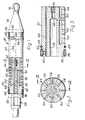
- a preferred embodiment of the drain or pipeline repairing of the invention comprises an ejector body, indicated generally by the reference numeral 20, whose overall configuration is cylindrical or tubular and which is composed of two sections 22, 24 of which one is shown in more detail in Fig. 3.
- These two sections 22, 24 are substantially identical in form, and are disposed in reversed disposition, end-to-end, relative to one another. They may be, for example, of metal, or a moulded plastics material, preferably the latter so that they may economically be discarded after a small number of uses of the apparatus.
- the sections 22, 24 are preferably of flexible material to enable them to be used in curved drains or pipelines.
- Each of the tubular sections 22, 24 has a relatively wide main bore portion 26 extending from one end thereof and merging into a narrower portion 28 having a threaded portion 30 accommodating a connecting bush 32 whereby the two sections are coupled together.
- the main bore portion 26 accommodates a succession of mixing elements 34 of which the details are shown in Fig. 7, 8 and 9 and will be described later.
- each body section Adjacent one end, each body section has a circumferential recess 36 accommodating a respective inflatable ring 38 fitted with an inflation valve 40 (in a manner similar to the fitting of a valve into a bicycle tyre inner tube), this valve 40 and the surrounding inflatable ring part being a push sealing fit in a radial opening 42, in the body section, leading to an axial inflation passage 44.
- Adjacent the inflatable ring 38, disposed in a groove defined between two circumferential ridges 46 is a respective 0-ring 48.
- the wide main bore portion 26 connects with a plurality of radial passages 50 which communicate with a corresponding array of axial setting-material passages 52 which in turn connect with a multitude of radial outlets 54 which open to the outer curved surface of the body section.
- an end plate or manifold 56 is bolted thereto and this embodies a coupling for supply ducts, indicated generally by numeral 58, which may be of sectional extensible construction, and which serve to supply the components of a multi component (e.g. two-component) setting composition, for instance an epoxy resin and a hardener, to the main bore portion 26, and to supply compressed air to the inflation passage 44.
- a multi component setting composition for instance an epoxy resin and a hardener
- each of the mixing elements 34 disposed in the main bore portion 26 is of circular form in end view, so as to be a snug sliding fit in the bore portion 26, but is shaped at its: rear end to provide angled surfaces 62, 64 meeting on a diametrical line 66 along which is a series of holes 6ti, 70, 72 and 74.
- the element 34 is of complementary angled configuration, as at 176 in Fig. 7, to interfit into the rear end of the next adjacent said mixing element 34, but is formed with a generally square recess 178 into which the holes 68 to 74 open along an imaginary diametrical line which is at right angles to the line 66.
- this arrangement provides for there to be a free space (defined by the respective recess 78) between each adjacent pair of the mixing elements , 34, and that the holes 68 to 74 are generally in a disposition approximating to a helical configuration, so that liquid material passing through the successive elements 34 from free space to free space will be caused to swirl, and good mixing is achieved in the free spaces.
- a tapered head 76 is bolted thereto, and this is provided with an eye 78 whereby a cable 80 (see Figs. 4 to 6) may be connected thereto.
- Figs. 4, 5 and 6 illustrate the method of using the apparatus as so far described for the repair of a defect in a drain or pipeline 82, this defect being illustrated as being a collapse of a portion of two adjacent drain or pipeline sections 84 and 86 in register with the usual joint therebetween, to the extent that a large part of the drain or pipeline, as well as the ground thereabove, has been washed away, as indicated at 88, 90.
- the cable 80 is threaded through the drain or pipeline 82 from an appropriate location such as an inspection chamber (not shown) to one side of the defect 88, 90 and this is connected to the eye 78 of the body 20, the latter being registered with the drain or pipeline at a suitable location (again for instance, an inspection chamber, not shown).
- the body 20 is drawn along the drain or pipeline 82 to the position illustrated wherein its leading end and its trailing end are to each side of the defect 88, 90, sections of ducting 58 being added as appropriate.
- the body can be moved along the drain or pipeline by the use of interconnecting rods.
- the ducting 58 is connected to a compressed air or hydraulic liquid supply to supply air or liquid to the rings 38 to inflate them as shown in Fig. 5 thereby to centre the body 20 and to seal the drain or pipeline 82 at each side of the defect 88, 90. If, as sometimes may be the case, the defect should register with or be disposed closely adjacent to a junction or side connection to the drain or pipeline 82, this junction or side connection will be blocked off using a bag (not shown) which can be inflated from the same compressed air or liquid source.
- the components of a two-component setting composition is rapidly pumped, in accurately metered quantities, and at high pressure, through the ducting, separately to the manifold 56 to enter the main bore portion 26 separately and mix therein as they pass through the mixing elements 34.
- the components preferably comprise a resinous compound and a hardener respectively, being such that they will aet to a relatively coherent mass preferably within two or three minutes and to a hard mass within six to eight minutes depending on ambient temperatures and quantities injected.
- the pumping-in of the setting composition components is effected rapidly to fill the defect 88, 90, as shown in Fig. 5, and the body 20 is allowed to remain in position just sufficient time for coherence to be achieved.
- the body 20 is drawn back along the drain or pipeline 82 by means of the ducting 58 or by connected cable or rods (not shown) which, of course is dismantled or rewound appropriately.
- the moving body 20, as it is drawn back, may deposit a thin layer of the setting material on the interior of the non-defective drain or pipeline part, but this need not be a disadvantage.
- the inflatable rings 38 can be controlledly deflated or inflated during the moving-back of the body 20 so as to ensure that there is a taper of the setting material surface, merging smoothly with the inner surface of the drain or pipeline 82, and no step or obstruction is created.
- the body 20 can be cleared of setting composition components, provided they have not set hard, and may be reused a number of times.
- the pipelines to the body remain full of the separately delivered resinous compound and hardener and do not require to be cleared between operations, of course.
- FIG. 10 of the drawings this figure illustrates a practical embodiment of a reamer which may be employed in conjunction with the apparatus above described.
- This comprises an air motor, indicated generally by the reference numeral 100, located by one end in a tubular adapter 102 whose size is selected according to the size of the drain 104 which is being repaired and which has its own inflatable circumferential ring 106 inflation of which serves to fix the reamer axially within the drain or pipeline 104.
- the other end of the motor 100 has bolted thereon a steadying and centring disc 108 serving rotatably to support, by a bearing 110, an intermediate stub 112 with a shank 114 thereof slidably, but nbn-rotatably, engaged into a sleeve 116 secured to shaft 118 of the motor 100.
- a spring 120 abuts by one end against a shoulder on the sleeve 116 and by the other end against a collar 122 on the stub 112 whereby the latter is yieldingly loaded forwardly in the axial direction away from the motor 100.
- a boss 126 Secured onto the front end 124, which is non- round, of the intermediate stub 112 is a boss 126, whereby a cylindrical reaming tool 128, which may be toothed at its front end away from the motor 100, is secured to the stub 112 by way of a rear end disc 130 of the tool 128.
- a cleat 132 is rotatably fixed axially to the boss 126, within the tool 128, and this enables attachment of a hauling cable 134 to the reamer.
- the rear of the reamer may be provided with a rodding connector to facilitate pushing through a drain or pipeline and also withdrawal as may be necessary, in cases where pulling through may be impracticable.
- a fluid supply duct arrangement 136 Connected to the rear end of the air motor 100 is a fluid supply duct arrangement 136 whereby air or liquid can be supplied (a) to the inflatable ring 106 for arresting the reamer in the drain or pipeline 104 and (b) for driving the motor 100 so as to rotate the tool 128.
- This reamer may be used either before use of the apparatus already described, or after the use of such apparatus, or both.
- an internal inspection will be made of the drain or pipe line 104 to determine what repair(s) may be necessary, for example by use of closed circuit television scanning. If this should reveal the presence of any obstruction, such as debris fallen into and lodged in the drain or pipeline, or external matter such as rocks projecting into the opening of the drain or pipeline, or the fact that the shape of the drain or pipeline has been deformed from its intended round cross-section, the reamer will then be drawn through the drain or pipeline, so as to pass and clear the region to be repaired, thereby preparing the drain or pipeline for the repairing operation above described.
- the reamer may then be drawn through so as to ensure that the inner cross-section is trued up, and if desired a polishing tool may be employed in the place of the tool 128 for polishing the internal surface of the newly-introduced hardening compound.
- the ejector body 20 may be adapted to be pushed through the pipeline instead of being pulled as in the described embodiment. It may be of unitary construction; in the form illustrated, one or more intermediate sections may be incorporated between the body sections 22 and 24 to achieve an overall body length as may be desired or dictated according to the extent of the repair to be effected.
- the body sections may, if desired, be produced as cheap disposible plastics mouldings which can, if necessary, be discarded after only one or two uses; moreover they may be made of flexible materials for use in curved drains or pipelines.
- the apparatus can, of course, be used to repair all kinds of defects from very minor cracks or leaks up to major collapses as illustrated.
- the ejector body and/or the reamer arrangement may, if desired, be adapted to be positioned in and/or progressed through the drain or pipeline by means of a tractor which may be driven pneumatically, electrically or in any other suitable way.
Landscapes
- Engineering & Computer Science (AREA)
- General Engineering & Computer Science (AREA)
- Mechanical Engineering (AREA)
- Chemical & Material Sciences (AREA)
- Combustion & Propulsion (AREA)
- Pipe Accessories (AREA)
- Medicines That Contain Protein Lipid Enzymes And Other Medicines (AREA)
Priority Applications (1)
| Application Number | Priority Date | Filing Date | Title |
|---|---|---|---|
| AT83302375T ATE22604T1 (de) | 1982-06-11 | 1983-04-27 | Verfahren und geraet zur reparatur von drains und unterirdisch verlegten rohren. |
Applications Claiming Priority (4)
| Application Number | Priority Date | Filing Date | Title |
|---|---|---|---|
| GB8217046 | 1982-06-11 | ||
| GB8217046 | 1982-06-11 | ||
| GB08307238A GB2122300B (en) | 1982-06-11 | 1983-03-16 | Repairing drains and underground pipelines |
| GB8307238 | 1983-03-16 |
Publications (2)
| Publication Number | Publication Date |
|---|---|
| EP0096958A1 true EP0096958A1 (de) | 1983-12-28 |
| EP0096958B1 EP0096958B1 (de) | 1986-10-01 |
Family
ID=26283083
Family Applications (1)
| Application Number | Title | Priority Date | Filing Date |
|---|---|---|---|
| EP83302375A Expired EP0096958B1 (de) | 1982-06-11 | 1983-04-27 | Verfahren und Gerät zur Reparatur von Drains und unterirdisch verlegten Rohren |
Country Status (7)
| Country | Link |
|---|---|
| US (1) | US4529008A (de) |
| EP (1) | EP0096958B1 (de) |
| AU (1) | AU550814B2 (de) |
| CA (1) | CA1202916A (de) |
| DE (1) | DE3366538D1 (de) |
| GB (1) | GB2122300B (de) |
| ZW (1) | ZW11483A1 (de) |
Cited By (7)
| Publication number | Priority date | Publication date | Assignee | Title |
|---|---|---|---|---|
| WO1985003758A1 (en) * | 1984-02-22 | 1985-08-29 | Rump Bent Joergen | Method and apparatus for the plugging of side openings of sewage pipes, particularly side or branch pipes of main sewer conduits |
| GB2204378A (en) * | 1987-05-08 | 1988-11-09 | Crux Engineering Limited | Conduit closure, e.g. for damage containment system |
| EP0393433A3 (de) * | 1989-04-20 | 1991-12-18 | THEODOR BREE, BAUSTOFF- UND CEMENTWAREN GMBH & CO | Verfahren zum Beschichten der Innenwandung eines Betonrohres und Vorrichtung zur Durchführung des Verfahrens |
| FR2696811A1 (fr) * | 1992-10-09 | 1994-04-15 | Weber Adolphe | Procédé de détection et de réparation d'une fuite de canalisation en zone de nappe phréatique, depuis la surface, et dispositif pour la mise en Óoeuvre de ce procédé. |
| WO2009015641A1 (de) * | 2007-08-01 | 2009-02-05 | Hochschule Ostwestfalen-Lippe | Sanierungsverfahren |
| WO2015114243A1 (fr) * | 2014-01-28 | 2015-08-06 | Gdf Suez | Outil pour intervention sur la paroi d'une canalisation - méthode associée |
| US10295103B1 (en) | 2018-03-08 | 2019-05-21 | Car-Ber Investments Inc. | Inflatable isolation tool with enhanced monitoring unit |
Families Citing this family (22)
| Publication number | Priority date | Publication date | Assignee | Title |
|---|---|---|---|---|
| GB8314209D0 (en) * | 1983-05-23 | 1983-06-29 | British Gas Corp | Sealing joints and leaks in mains |
| US4799305A (en) * | 1984-12-27 | 1989-01-24 | Westinghouse Electric Corp. | Tube protection device |
| US4752511A (en) * | 1986-08-15 | 1988-06-21 | Insituform International Nv | Method and apparatus for sealing the space between pipes and linings therefor |
| FR2615207B1 (fr) * | 1987-05-14 | 1991-11-22 | Framatome Sa | Canne tubulaire pour le traitement de la surface interieure d'un tube |
| US4901424A (en) * | 1988-07-26 | 1990-02-20 | Insituform Of North America, Inc. | Method of forming an end seal for a pipe liner |
| DE4119161A1 (de) * | 1991-06-11 | 1992-12-17 | Werner & Pfleiderer | Verfahren und vorrichtung zum auskleiden der innenwand eines kanalrohres |
| FR2718665B1 (fr) * | 1994-04-15 | 1996-07-12 | Stolt Comex Seaway | Outil de découpe de tuyauterie immergée par jet abrasif. |
| US5653555A (en) * | 1995-05-19 | 1997-08-05 | Inliner, U.S.A. | Multiple resin system for rehabilitating pipe |
| US5699838A (en) * | 1995-05-22 | 1997-12-23 | Inliner, U.S.A. | Apparatus for vacuum impregnation of a flexible, hollow tube |
| GB9911289D0 (en) * | 1999-05-17 | 1999-07-14 | Longrock Ground Works Ltd | Method and apparatus for reinstating drains or underground passages |
| US6416692B1 (en) * | 2000-03-10 | 2002-07-09 | Jeffrey L. Iwasaki-Higbee | Sewer system pipe repairs |
| US7096890B2 (en) | 2002-06-19 | 2006-08-29 | Saint-Gobain Technical Fabrics Canada, Ltd. | Inversion liner and liner components for conduits |
| US7478650B2 (en) | 2002-06-19 | 2009-01-20 | Saint-Gobain Technical Fabrics Canada, Ltd. | Inversion liner and liner components for conduits |
| DE102004036425C5 (de) * | 2004-07-27 | 2009-07-02 | Tracto-Technik Gmbh | Vorrichtung und Verfahren zum Verbinden eines Rohrstrangs mit einem Bohr-, Aufweit- oder Einzugsgerät |
| GB2473594B (en) * | 2009-06-09 | 2013-09-18 | Balfour Beatty Plc | Live pipe lining pig with centre bore |
| US8186385B2 (en) * | 2009-07-06 | 2012-05-29 | Iwasaki-Higbee Jeffrey L | Packer for installing sealant in defective conduits |
| US9757599B2 (en) | 2014-09-10 | 2017-09-12 | Dymat Construction Products, Inc. | Systems and methods for fireproofing cables and other structural members |
| US10746341B2 (en) | 2017-03-15 | 2020-08-18 | Titan CMP Solutions LLC | Pusher box for nondestructive pipe refurbishment in confined spaces |
| US11892114B2 (en) | 2017-03-15 | 2024-02-06 | Titan CMP Solutions LLC | Expander with accessories to adjust nominal size |
| CN110067945B (zh) * | 2019-04-28 | 2020-11-10 | 徐州轩科农业机械有限公司 | 一种用于卫浴洁具中马桶内管的检漏深入修补设备 |
| US12060963B1 (en) * | 2023-04-19 | 2024-08-13 | Danny Warren Consulting, LLC. | Method and system for encapsulating in-ground asbestos concrete pipe |
| CN116951172A (zh) * | 2023-06-05 | 2023-10-27 | 湖北伟通管业科技有限公司 | 一种聚乙烯pe给水输送用非开挖式管道及其牵引装置 |
Citations (4)
| Publication number | Priority date | Publication date | Assignee | Title |
|---|---|---|---|---|
| DD81276A (de) * | ||||
| DE2053725A1 (de) * | 1969-11-03 | 1971-05-13 | Granit Och Beton Ab | Verfahren und Vorrichtung zum Abdich ten einer Leckstelle in Leitungen |
| US3762446A (en) * | 1970-12-08 | 1973-10-02 | Minnesota Mining & Mfg | Method and device for internally locating and sealing pipeline leaks |
| CH603254A5 (de) * | 1974-10-15 | 1978-08-15 | Niedung Juergen Kg |
Family Cites Families (11)
| Publication number | Priority date | Publication date | Assignee | Title |
|---|---|---|---|---|
| GB212715A (en) * | 1923-02-10 | 1924-03-20 | Frederick Leonard Ball | Improvements in or relating to apparatus for testing pipe-joints for leakage |
| US2187275A (en) * | 1937-01-12 | 1940-01-16 | Amos N Mclennan | Means for locating and cementing off leaks in well casings |
| US3129759A (en) * | 1961-04-05 | 1964-04-21 | Halliburton Co | Casing alignment and cementing tool and method |
| US3103235A (en) * | 1961-09-29 | 1963-09-10 | Penetryn System | Sleeve packer for chemical grouting |
| US3307996A (en) * | 1963-03-29 | 1967-03-07 | Pan American Petroleum Corp | Method for placing a protective coating on the interior of a pipe |
| US3269421A (en) * | 1964-02-11 | 1966-08-30 | Halliburton Co | Packer for grouting conduits |
| US3606913A (en) * | 1968-12-13 | 1971-09-21 | Inst Gas Technology | Apparatus for internally sealing pipes |
| US3618639A (en) * | 1969-11-24 | 1971-11-09 | Cues Inc | Packer for sealing pipe leaks |
| DE7209732U (de) * | 1971-03-24 | |||
| US3894131A (en) * | 1972-05-18 | 1975-07-08 | Minnesota Mining & Mfg | Poly(urethane-urea) sealants and sealing underground structures therewith |
| US3834422A (en) * | 1973-01-19 | 1974-09-10 | Cherne Ind Inc | Sewer repair apparatus |
-
1983
- 1983-03-16 GB GB08307238A patent/GB2122300B/en not_active Expired
- 1983-04-27 EP EP83302375A patent/EP0096958B1/de not_active Expired
- 1983-04-27 CA CA000426875A patent/CA1202916A/en not_active Expired
- 1983-04-27 DE DE8383302375T patent/DE3366538D1/de not_active Expired
- 1983-04-28 US US06/489,541 patent/US4529008A/en not_active Expired - Lifetime
- 1983-05-04 AU AU14219/83A patent/AU550814B2/en not_active Ceased
- 1983-05-12 ZW ZW114/83A patent/ZW11483A1/xx unknown
Patent Citations (4)
| Publication number | Priority date | Publication date | Assignee | Title |
|---|---|---|---|---|
| DD81276A (de) * | ||||
| DE2053725A1 (de) * | 1969-11-03 | 1971-05-13 | Granit Och Beton Ab | Verfahren und Vorrichtung zum Abdich ten einer Leckstelle in Leitungen |
| US3762446A (en) * | 1970-12-08 | 1973-10-02 | Minnesota Mining & Mfg | Method and device for internally locating and sealing pipeline leaks |
| CH603254A5 (de) * | 1974-10-15 | 1978-08-15 | Niedung Juergen Kg |
Cited By (10)
| Publication number | Priority date | Publication date | Assignee | Title |
|---|---|---|---|---|
| WO1985003758A1 (en) * | 1984-02-22 | 1985-08-29 | Rump Bent Joergen | Method and apparatus for the plugging of side openings of sewage pipes, particularly side or branch pipes of main sewer conduits |
| GB2204378A (en) * | 1987-05-08 | 1988-11-09 | Crux Engineering Limited | Conduit closure, e.g. for damage containment system |
| EP0393433A3 (de) * | 1989-04-20 | 1991-12-18 | THEODOR BREE, BAUSTOFF- UND CEMENTWAREN GMBH & CO | Verfahren zum Beschichten der Innenwandung eines Betonrohres und Vorrichtung zur Durchführung des Verfahrens |
| FR2696811A1 (fr) * | 1992-10-09 | 1994-04-15 | Weber Adolphe | Procédé de détection et de réparation d'une fuite de canalisation en zone de nappe phréatique, depuis la surface, et dispositif pour la mise en Óoeuvre de ce procédé. |
| WO2009015641A1 (de) * | 2007-08-01 | 2009-02-05 | Hochschule Ostwestfalen-Lippe | Sanierungsverfahren |
| WO2015114243A1 (fr) * | 2014-01-28 | 2015-08-06 | Gdf Suez | Outil pour intervention sur la paroi d'une canalisation - méthode associée |
| US10215323B2 (en) | 2014-01-28 | 2019-02-26 | Engie | Tool for working on the wall of a pipe and related method |
| US10605396B2 (en) | 2014-01-28 | 2020-03-31 | Engie | Tool for working on the wall of a pipe and related method |
| US10605397B2 (en) | 2014-01-28 | 2020-03-31 | Engie | Tool for working on the wall of a pipe and related method |
| US10295103B1 (en) | 2018-03-08 | 2019-05-21 | Car-Ber Investments Inc. | Inflatable isolation tool with enhanced monitoring unit |
Also Published As
| Publication number | Publication date |
|---|---|
| AU1421983A (en) | 1983-12-15 |
| CA1202916A (en) | 1986-04-08 |
| US4529008A (en) | 1985-07-16 |
| ZW11483A1 (en) | 1983-07-27 |
| EP0096958B1 (de) | 1986-10-01 |
| GB2122300A (en) | 1984-01-11 |
| GB8307238D0 (en) | 1983-04-20 |
| GB2122300B (en) | 1985-07-24 |
| DE3366538D1 (en) | 1986-11-06 |
| AU550814B2 (en) | 1986-04-10 |
Similar Documents
| Publication | Publication Date | Title |
|---|---|---|
| US4529008A (en) | Method of and apparatus for repairing drains and underground pipelines | |
| US3602263A (en) | Pipe relining method and apparatus | |
| AU628420B2 (en) | Process for repairing an inaccessible domestic pipe using a remote-controlled device operating in the main | |
| EP0489090B1 (de) | Vorrichtung und verfahren zur reparatur von brüchen in unterirdischen leitungen | |
| EP0559592B1 (de) | Vorrichtung zur In-situ-Sanierung von nichtbegehbaren Rohrleitungen oder Kanälen und Verfahren zur Wiederherstellung mit Hilfe dieser Vorrichtung | |
| US4245970A (en) | Apparatus having a tubular inflatable bladder and a grout dispensing nozzle for connecting lateral branches to a relined main | |
| FI84925C (fi) | Omfordring av avloppsroer och liknande. | |
| CA2275793C (en) | Testing of plumbing installations and plumbing tool | |
| US6792820B2 (en) | Method and accessories for pipe replacement | |
| US4411459A (en) | Branch fitting for providing access to the interior of a pipe | |
| EP1064491B1 (de) | System und verfahren zur innenbeschichtigung von verbindungsstellen oder anderen sprungstellen in gasführenden röhren | |
| KR101272137B1 (ko) | 하수관내 이물질 제거장치 | |
| US4886396A (en) | Existing pipeline renewing method and apparatus therefor | |
| KR102051615B1 (ko) | 비굴착식 상하수도관 보수공법 | |
| JPH06500607A (ja) | パイプ清掃用の装置および方法 | |
| CN116447428B (zh) | 一种地下管网非开挖修复工艺 | |
| GB2169983A (en) | Repairing drains and pipelines | |
| KR100383237B1 (ko) | 비굴착 방식에 의한 하수관과 가지관의 연결 부위 보수장치 및 이를 이용한 보수공법 | |
| CN114198059B (zh) | 一种岩土钻孔祛污装置及使用方法 | |
| EP0717825A1 (de) | Reparatur von abwasserkanälen und rohrleitungen | |
| US5969234A (en) | Apparatus for repairing and/or leakage testing of sewer pipes | |
| JPH0975882A (ja) | 差圧駆動式管内掃除・補修・通線方法と、その装置 | |
| GB2141514A (en) | Branch fitting for providing access to the interior of a pipe | |
| KR20250001642A (ko) | 노후 배관 갱생용 배관 청소장치 및 이를 이용한 배관 클리닝 공법 | |
| JP3359619B2 (ja) | 推進工法用の掘進機の発進方法 |
Legal Events
| Date | Code | Title | Description |
|---|---|---|---|
| PUAI | Public reference made under article 153(3) epc to a published international application that has entered the european phase |
Free format text: ORIGINAL CODE: 0009012 |
|
| AK | Designated contracting states |
Designated state(s): AT CH DE FR LI NL SE |
|
| 17P | Request for examination filed |
Effective date: 19840421 |
|
| RAP1 | Party data changed (applicant data changed or rights of an application transferred) |
Owner name: A.M.K. PIPE TECHNOLOGY LIMITED |
|
| RIN1 | Information on inventor provided before grant (corrected) |
Inventor name: APPLETON, WILLIAM JOHN |
|
| GRAA | (expected) grant |
Free format text: ORIGINAL CODE: 0009210 |
|
| AK | Designated contracting states |
Kind code of ref document: B1 Designated state(s): AT CH DE FR LI NL SE |
|
| REF | Corresponds to: |
Ref document number: 22604 Country of ref document: AT Date of ref document: 19861015 Kind code of ref document: T |
|
| REF | Corresponds to: |
Ref document number: 3366538 Country of ref document: DE Date of ref document: 19861106 |
|
| ET | Fr: translation filed | ||
| PLBE | No opposition filed within time limit |
Free format text: ORIGINAL CODE: 0009261 |
|
| STAA | Information on the status of an ep patent application or granted ep patent |
Free format text: STATUS: NO OPPOSITION FILED WITHIN TIME LIMIT |
|
| 26N | No opposition filed | ||
| EAL | Se: european patent in force in sweden |
Ref document number: 83302375.7 |
|
| PGFP | Annual fee paid to national office [announced via postgrant information from national office to epo] |
Ref country code: FR Payment date: 19970416 Year of fee payment: 15 |
|
| PGFP | Annual fee paid to national office [announced via postgrant information from national office to epo] |
Ref country code: SE Payment date: 19970418 Year of fee payment: 15 |
|
| PGFP | Annual fee paid to national office [announced via postgrant information from national office to epo] |
Ref country code: DE Payment date: 19970419 Year of fee payment: 15 |
|
| PGFP | Annual fee paid to national office [announced via postgrant information from national office to epo] |
Ref country code: NL Payment date: 19970424 Year of fee payment: 15 Ref country code: AT Payment date: 19970424 Year of fee payment: 15 |
|
| PGFP | Annual fee paid to national office [announced via postgrant information from national office to epo] |
Ref country code: CH Payment date: 19970429 Year of fee payment: 15 |
|
| PG25 | Lapsed in a contracting state [announced via postgrant information from national office to epo] |
Ref country code: AT Free format text: LAPSE BECAUSE OF NON-PAYMENT OF DUE FEES Effective date: 19980427 |
|
| PG25 | Lapsed in a contracting state [announced via postgrant information from national office to epo] |
Ref country code: SE Free format text: LAPSE BECAUSE OF NON-PAYMENT OF DUE FEES Effective date: 19980428 |
|
| PG25 | Lapsed in a contracting state [announced via postgrant information from national office to epo] |
Ref country code: LI Free format text: LAPSE BECAUSE OF NON-PAYMENT OF DUE FEES Effective date: 19980430 Ref country code: FR Free format text: THE PATENT HAS BEEN ANNULLED BY A DECISION OF A NATIONAL AUTHORITY Effective date: 19980430 Ref country code: CH Free format text: LAPSE BECAUSE OF NON-PAYMENT OF DUE FEES Effective date: 19980430 |
|
| PG25 | Lapsed in a contracting state [announced via postgrant information from national office to epo] |
Ref country code: NL Free format text: LAPSE BECAUSE OF NON-PAYMENT OF DUE FEES Effective date: 19981101 |
|
| REG | Reference to a national code |
Ref country code: CH Ref legal event code: PL |
|
| NLV4 | Nl: lapsed or anulled due to non-payment of the annual fee |
Effective date: 19981101 |
|
| EUG | Se: european patent has lapsed |
Ref document number: 83302375.7 |
|
| PG25 | Lapsed in a contracting state [announced via postgrant information from national office to epo] |
Ref country code: DE Free format text: LAPSE BECAUSE OF NON-PAYMENT OF DUE FEES Effective date: 19990202 |
|
| REG | Reference to a national code |
Ref country code: FR Ref legal event code: ST |