EP0096964B1 - Überbrückungskupplung für Drehmomentwandler - Google Patents
Überbrückungskupplung für Drehmomentwandler Download PDFInfo
- Publication number
- EP0096964B1 EP0096964B1 EP83302624A EP83302624A EP0096964B1 EP 0096964 B1 EP0096964 B1 EP 0096964B1 EP 83302624 A EP83302624 A EP 83302624A EP 83302624 A EP83302624 A EP 83302624A EP 0096964 B1 EP0096964 B1 EP 0096964B1
- Authority
- EP
- European Patent Office
- Prior art keywords
- annular
- wall member
- side wall
- radially
- clutch assembly
- Prior art date
- Legal status (The legal status is an assumption and is not a legal conclusion. Google has not performed a legal analysis and makes no representation as to the accuracy of the status listed.)
- Expired
Links
- 230000008878 coupling Effects 0.000 claims description 33
- 238000010168 coupling process Methods 0.000 claims description 33
- 238000005859 coupling reaction Methods 0.000 claims description 33
- 230000005540 biological transmission Effects 0.000 claims description 20
- 230000002093 peripheral effect Effects 0.000 claims description 19
- 239000012530 fluid Substances 0.000 claims description 10
- 238000007789 sealing Methods 0.000 claims description 6
- 239000000446 fuel Substances 0.000 description 5
- 230000000694 effects Effects 0.000 description 3
- 229920001296 polysiloxane Polymers 0.000 description 3
- 229910000760 Hardened steel Inorganic materials 0.000 description 2
- XEEYBQQBJWHFJM-UHFFFAOYSA-N Iron Chemical compound [Fe] XEEYBQQBJWHFJM-UHFFFAOYSA-N 0.000 description 2
- 238000005266 casting Methods 0.000 description 2
- 229920001971 elastomer Polymers 0.000 description 2
- 239000000806 elastomer Substances 0.000 description 2
- 229910000906 Bronze Inorganic materials 0.000 description 1
- 229910000831 Steel Inorganic materials 0.000 description 1
- XAGFODPZIPBFFR-UHFFFAOYSA-N aluminium Chemical compound [Al] XAGFODPZIPBFFR-UHFFFAOYSA-N 0.000 description 1
- 229910052782 aluminium Inorganic materials 0.000 description 1
- 239000010974 bronze Substances 0.000 description 1
- 238000002485 combustion reaction Methods 0.000 description 1
- 230000000295 complement effect Effects 0.000 description 1
- 238000010276 construction Methods 0.000 description 1
- KUNSUQLRTQLHQQ-UHFFFAOYSA-N copper tin Chemical compound [Cu].[Sn] KUNSUQLRTQLHQQ-UHFFFAOYSA-N 0.000 description 1
- 235000013870 dimethyl polysiloxane Nutrition 0.000 description 1
- 239000004205 dimethyl polysiloxane Substances 0.000 description 1
- -1 for example Substances 0.000 description 1
- 229910052742 iron Inorganic materials 0.000 description 1
- 239000007788 liquid Substances 0.000 description 1
- 230000007774 longterm Effects 0.000 description 1
- 238000004519 manufacturing process Methods 0.000 description 1
- 229920000435 poly(dimethylsiloxane) Polymers 0.000 description 1
- 239000007787 solid Substances 0.000 description 1
- 239000010959 steel Substances 0.000 description 1
Images

Classifications
-
- F—MECHANICAL ENGINEERING; LIGHTING; HEATING; WEAPONS; BLASTING
- F16—ENGINEERING ELEMENTS AND UNITS; GENERAL MEASURES FOR PRODUCING AND MAINTAINING EFFECTIVE FUNCTIONING OF MACHINES OR INSTALLATIONS; THERMAL INSULATION IN GENERAL
- F16H—GEARING
- F16H45/00—Combinations of fluid gearings for conveying rotary motion with couplings or clutches
- F16H45/02—Combinations of fluid gearings for conveying rotary motion with couplings or clutches with mechanical clutches for bridging a fluid gearing of the hydrokinetic type
-
- F—MECHANICAL ENGINEERING; LIGHTING; HEATING; WEAPONS; BLASTING
- F16—ENGINEERING ELEMENTS AND UNITS; GENERAL MEASURES FOR PRODUCING AND MAINTAINING EFFECTIVE FUNCTIONING OF MACHINES OR INSTALLATIONS; THERMAL INSULATION IN GENERAL
- F16D—COUPLINGS FOR TRANSMITTING ROTATION; CLUTCHES; BRAKES
- F16D35/00—Fluid clutches in which the clutching is predominantly obtained by fluid adhesion
-
- F—MECHANICAL ENGINEERING; LIGHTING; HEATING; WEAPONS; BLASTING
- F16—ENGINEERING ELEMENTS AND UNITS; GENERAL MEASURES FOR PRODUCING AND MAINTAINING EFFECTIVE FUNCTIONING OF MACHINES OR INSTALLATIONS; THERMAL INSULATION IN GENERAL
- F16H—GEARING
- F16H45/00—Combinations of fluid gearings for conveying rotary motion with couplings or clutches
- F16H45/02—Combinations of fluid gearings for conveying rotary motion with couplings or clutches with mechanical clutches for bridging a fluid gearing of the hydrokinetic type
- F16H2045/0221—Combinations of fluid gearings for conveying rotary motion with couplings or clutches with mechanical clutches for bridging a fluid gearing of the hydrokinetic type with damping means
- F16H2045/0242—Combinations of fluid gearings for conveying rotary motion with couplings or clutches with mechanical clutches for bridging a fluid gearing of the hydrokinetic type with damping means with viscous dampers
-
- F—MECHANICAL ENGINEERING; LIGHTING; HEATING; WEAPONS; BLASTING
- F16—ENGINEERING ELEMENTS AND UNITS; GENERAL MEASURES FOR PRODUCING AND MAINTAINING EFFECTIVE FUNCTIONING OF MACHINES OR INSTALLATIONS; THERMAL INSULATION IN GENERAL
- F16H—GEARING
- F16H45/00—Combinations of fluid gearings for conveying rotary motion with couplings or clutches
- F16H45/02—Combinations of fluid gearings for conveying rotary motion with couplings or clutches with mechanical clutches for bridging a fluid gearing of the hydrokinetic type
- F16H2045/0273—Combinations of fluid gearings for conveying rotary motion with couplings or clutches with mechanical clutches for bridging a fluid gearing of the hydrokinetic type characterised by the type of the friction surface of the lock-up clutch
- F16H2045/0294—Single disk type lock-up clutch, i.e. using a single disc engaged between friction members
Definitions
- This invention relates to automatic torque converter transmission for motor vehicle applications. More particularly, it relates to automatic torque converter transmissions having means to selectively bypass the torque converter and, even more particularly, to a viscous coupling utilized in a torque converter bypass.
- Torque converter type automatic transmissions have achieved almost universal application and acceptance in motor vehicles. While generally satisfactory in this application, torque converter automatic transmissions embody inherent slip and therefore incorporate inherent losses in vehicular fuel economy. In an effort to minimize this slippage and thereby optimize fuel economy, various efforts have been made to bypass the torque converter with some manner of direct drive which is typically brought into play when the vehicle is operating in the higher gear speed ratios and above a predetermined vehicular speed. While these direct drive bypass arrangements have resulted in improvements in fuel economy, they have also, under certain conditions, served to transmit various drive line vibrations to the passenger compartment of the motor vehicle, resulting a derogation in the ride quality of the vehicle.
- a viscous coupling be employed in the bypass drivetrain. While the use of a viscous coupling in the bypass drivetrain does serve to minimize transmission of drive line vibrations to the passenger compartment, it is imperative that the coupling be designed for maximum efficiency so that losses in the coupling itself cannot significantly offset the fuel economy gains achieved by the use of the bypass.
- a viscous coupling for bypassing the torque converter of a transmission according to the preamble of Claim 1 is shown in U.S. Patent 4,317,510.
- the coupling includes an annular housing assembly and an annular clutch assembly adapted to be positioned in a torque converter housing.
- the housing assembly includes a first annular side wall member and a radially extending clutch surface adapted for clutching coaction with a confronting inner surface of the torque converter.
- the clutch assembly includes an annular radially extending portion defining a working surface on an annular side face thereof for viscous clutching coaction with a corresponding working surface on a confronting annular face of the annular side wall member of the housing assembly, and an annular axially extending hub portion adapted to be drivingly connected to an outlet shaft of the torque converter.
- the torque converter viscous bypass coupling of the present invention is as defined in claim 1.
- the drive for the torque converter housing is directly into the first annular side wall member so that accurate registration of the second annular side wall member relative to the first member, and preclusion of relative slippage between the first member and second member, and no longer critical to the long-term ability of the coupling to continue to operate within design specifications.
- the motor vehicle drivetrain seen schematically in Figure 1 includes an internal combustion engine 10, an automatic transmission 11 and a propeller shaft 12 driving rear wheels 13 through a differential 14.
- Transmission 11 includes a torque converter 15 having an output shaft 16 and a gear ratio box 18 driven by torque converter output shaft 16.
- Torque converter 15 is filled with automatic transmission fluid and includes, in known manner, a pump 20 driven from engine 10 through torque converter housing 22, a stator 24, and a turbine 26 driven hydrokinetically by pump 20.
- Torque converter 15 further includes a bypass drive line seen generally at 27 in Figure 1.
- Bypass drive line 27 is effective when actuated to provide a direct drive between torque converter housing 22 and torque converter output shaft 16 through viscous coupling 30 thereby bypassing the high slippage drivepath through pump 20 and turbine 26.
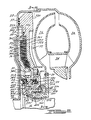
- Turbine 26, as seen in Figure 2, is secured by rivets 28 to an annular mounting member 29.
- Mounting member 29 includes an annular radially extending mounting portion 29a and an annular axially extending hub portion 29b extending leftwardly from the radially inner edge of mounting portion 29a.
- Hub portion 29b in turn includes a relatively thick portion 29c and a relatively thin free end portion 29d.
- the inner periphery of portion 29b is splined at 29e for coaction with splines 16a on output shaft 16, whereby rotation of turbine 26 effects rotation of output shaft 16.
- Viscous coupling 30 is generally circular and generally planar and is of a sandwich construction and includes an annular housing assembly, adapted to be positioned within the housing 22 of the torque converter and having axially spaced annular side wall members defining an annular clutch chamber therebetween, and an annular clutch member disposed within the clutch chamber.
- One side wall of the annular housing is constituted by a body member 32 and the other side wall member of the annular housing is constituted by a cover member 34.
- Clutch member 36 is interposed between body 32 and cover 34.
- Cover 34 is preferably formed as a steel stamping and body 32 and clutch 36 are preferably formed as permanent mold aluminum castings.
- Body 32 includes a radially outer peripheral portion 32a, an intermediate portion 32b, and a radially inner portion 32c terminating in a hub portion 32d extending axially leftwardly as viewed in Figure 2 from the radially inner end of the inner portion 32c.
- Intermediate portion 32b is machined on its inner or left, as viewed in Figure 2, face to form a series of annular lands 32e separated by a series of annular grooves 32f.
- Another annular groove 32g is machined in the inner face of body 32 radially outwardly of lands and grooves 32e, 32f.
- An annular clutch lining 37 is adhesively secured to the inner or left face of outer peripheral portion 32a for clutching coaction with the confronting inner surface 22a of torque converter housing 22.
- Cover 34 includes a radially outer peripheral portion 34a held in a position seated against the inner or left face of body outer peripheral portion 32a by a rollover 32h on body 32, an intermediate portion 34b, and a radially inner portion 34c terminating in an inwardly, or rightwardly, turned lip portion 34d.
- Clutch 36 includes a working portion 36a and a mounting portion 36b.
- the side of working portion 36a confronting body 32 (the right side in Figure 2) is machined to form a series of annular lands 36c separated by a series of annular grooves 36d, Lands 32e on body 32 are interdigi- tally arranged with respect to lands 36c on clutch 36.
- Mounting portion 36b is secured by rivets 39 to a clutch hub member 40 which, together with clutch 36, forms an annular clutch assembly.
- Clutch hub member 40 is formed as an iron casting and includes an annular radially extending mounting flange or bridge portion 40a receiving rivets 39, an annular axially extending seal or intermediate portion 40b extending leftwardly from the radially inner edge of bridge portion 40a, an annular radially extending end portion 40c, an annular axially extending hub portion 40d extending rightwardly from the radially inner edge of end portion 40c, and an annular flange portion 40d extending rightwardly from the radially inner edge of end portion 40c, and an annular flange portion 40e extending axially inwardly, or rightwardly, from flange portion 40a radially inwardly of rivets 39.
- Annular hub portion 40d in turn includes a relatively thick annular portion 40f and a relatively thin free end portion 40g which nest in complementary fashion with portions 29c and 29d of mounting member hub portion 29b.
- An annular wear sleeve 41 of hardened steel is pressed onto the outer periphery of portion 40b of clutch hub member 40.
- the inner periphery of portion 40g is splined at 40h for coaction with splines 29f on the outer periphery of portion 29c of mounting hub member 29.
- the inner periphery of portion 40f forms a cylindrical sealing surface for coaction with an elastomer square cut sealing ring seal 42 mounted in an annular groove in free end portion 29d of mounting hub member 29.
- Hub portion 32d of body 32 includes a relatively thick portion 32i and a relatively thin free end portion 32j.
- An annular wear sleeve 43 of hardened steel is pressed onto the outer periphery of relatively thick portion 32i.
- Relatively thin free end portion 32j extends axially into the U-shaped annular cavity defined by portions 40b, 40c and 40d of clutch hub member 40.
- Hub portion 32d is journaled on clutch hub portion 40d by bronze bushings 44 and 46 pressed onto body hub portion 32d.
- Bushing 44 is interposed between hub body portion 32j and clutch hub portion 40f with a flange portion 44a positioned between the free end annular edge of body hub portion 32j and the confronting annular surface of clutch hub portion 40c.
- Bushing 46 is interposed between body hub portion 32i and clutch hub portion 40g with a flange portion 46a received in an annular notch 32k formed in body hub portion 32d.
- a washer 48 held in place by a snap ring 50 received in a suitable annular groove in clutch hub portion 40g, limits axial movement of clutch hub portion 40d.
- Bushings 44 and 46 function to absorb the entire bearing load for body 32 and cover 34. And bushings 44, 46 coact with washer 48 and the inner face of clutch hub portion 40c to accurately locate body 32 with respect to clutch 36 so that the groove spacing between body member annular lands 32e and clutch member annular lands 32c can be accurately controlled. This spacing is critical from a design standpoint since it determines the amount of viscous driving force transmitted from the body to the clutch.
- the described bushing arrangement wherein both bushings are press fit into the same bore of the body hub portion, makes it easier to hold critical tolerances and dimensions so that frictional forces at the bearing interfaces are minimized and so that the critical groove spacing at the viscous interface of the clutch and body may be accurately controlled.
- the viscous coupling is filled with a silicone fluid, for example, dimethyl polysiloxane.
- a silicone fluid for example, dimethyl polysiloxane.
- the silicone liquid is prevented from escaping radially outwardly by an elastomeric square cut sealing ring seal 52 received in annular groove 32g.
- the silicone fluid is prevented from escaping radially inwardly by a pair of double-lip elastomer seals 54, 56 positioned respectively between the outer periphery of wear sleeve 41 and the confronting inner periphery of cover lip portion 34d, and between the outer periphery of wear sleeve 43 and the confronting inner periphery offlange 40e. Seals 54, 56 also preclude leakage of automatic transmission fluid into the viscous coupling.
- the direction of flow of the automatic transmission fluid in the torque converter is reversed by actuation of a suitable solenoid valve, not shown.
- the automatic transmission fluid is now admitted to the main chamber of the torque converter where it acts against body 32 and slides the viscous coupling to the left as viewed in Figure 2, to bring lining 37 into frictional engagement with housing surface 22a.
- the transmission now drives directly through the viscous coupling to output shaft 16, thereby bypassing the torque converter.
- the specific disclosed viscous coupling design provides simple, efficient transmission of power through the viscous coupling. Specifically, since the drive from the torque converter housing is directly into the body member of the coupling, rather than into the cover member as in previous designs, there is less concern for maintaining accurate registration between the cover member and the body member and less concern for relative slippage between the cover member and body member. And since the entire bearing load of the cover member and body member assembly is taken at the journal of the body member on the clutch member, the bearing design is simplified and bearing frictional losses may be minimized as compared to previous designs where the cover member and body member were separately journaled and the separate journals were subject to misalignment with consequent increases in bearing friction, or were subject to counteracting tendencies, with additional consequent increases in bearing friction.
- the described bearing arrangement also enables the body member to be accurately and consistently located with respect to the clutch member so that the drive groove spacing between these two members, critical to power transmission through the coupling, may be accurately controlled in a mass production environment.
Landscapes
- Engineering & Computer Science (AREA)
- General Engineering & Computer Science (AREA)
- Mechanical Engineering (AREA)
- Mechanical Operated Clutches (AREA)
- Pens And Brushes (AREA)
- Arrangement And Driving Of Transmission Devices (AREA)
Claims (8)
dadurch gekennzeichnet, daß:
Applications Claiming Priority (2)
| Application Number | Priority Date | Filing Date | Title |
|---|---|---|---|
| US06/388,557 US4496034A (en) | 1982-06-15 | 1982-06-15 | Viscous coupling for torque converter bypass |
| US388557 | 1982-06-15 |
Publications (2)
| Publication Number | Publication Date |
|---|---|
| EP0096964A1 EP0096964A1 (de) | 1983-12-28 |
| EP0096964B1 true EP0096964B1 (de) | 1986-09-10 |
Family
ID=23534609
Family Applications (1)
| Application Number | Title | Priority Date | Filing Date |
|---|---|---|---|
| EP83302624A Expired EP0096964B1 (de) | 1982-06-15 | 1983-05-10 | Überbrückungskupplung für Drehmomentwandler |
Country Status (4)
| Country | Link |
|---|---|
| US (1) | US4496034A (de) |
| EP (1) | EP0096964B1 (de) |
| JP (1) | JPS596463A (de) |
| DE (1) | DE3366006D1 (de) |
Families Citing this family (16)
| Publication number | Priority date | Publication date | Assignee | Title |
|---|---|---|---|---|
| US4674991A (en) * | 1980-02-28 | 1987-06-23 | Kabushiki Kaisha Daikin Seisakusho | Damper disc having annular protrusions and recesses |
| US4557357A (en) * | 1984-05-29 | 1985-12-10 | Eaton Corporation | Torsion damping mechanism with a viscous coupling |
| US4540076A (en) * | 1984-06-25 | 1985-09-10 | Eaton Corporation | Torque converter viscous bypass coupling with improved seal arrangement |
| US4828082A (en) * | 1988-02-19 | 1989-05-09 | General Motors Corporation | Control method for protecting a viscous converter clutch in a motor vehicle drivetrain |
| US5044675A (en) * | 1988-05-04 | 1991-09-03 | Rasmussen Gmbh | Hose coupling |
| DE69016723D1 (de) * | 1989-09-19 | 1995-03-23 | Mh Center Ltd | Metallmatrize zum plastischen Umformen eines Differentialritzels und Verfahren zum plastischen Umformen mit der Matrize. |
| US5125486A (en) * | 1990-08-31 | 1992-06-30 | Toyota Jidosha Kabushiki Kaisha | Fluid power transmission with a lock-up clutch |
| US5044477A (en) * | 1990-09-19 | 1991-09-03 | Eaton Corporation | Torque converter viscous coupling bypass element with improved seal arrangement |
| US5213186A (en) * | 1990-11-30 | 1993-05-25 | Toyota Jidosha Kabushiki Kaisha | Control system and method for automatic transmission |
| EP0533426B1 (de) * | 1991-09-20 | 1996-12-04 | Toyota Jidosha Kabushiki Kaisha | Hydraulische Drehmoment-Übertragungseinheit mit Überbrückungskupplung |
| US5172796A (en) * | 1992-03-18 | 1992-12-22 | Eaton Corporation | Reduced cost viscous coupling by-pass element for a torque converter |
| DE69314550T2 (de) * | 1992-07-03 | 1998-03-26 | Toyota Motor Co Ltd | Hydraulische Drehmoment-Übertragungseinheit mit Überbrückungskupplung |
| US5433304A (en) * | 1993-06-23 | 1995-07-18 | Eaton Corporation | Viscous coupling by-pass element having variable drive capability |
| US5975265A (en) * | 1998-06-24 | 1999-11-02 | Behr America, Inc. | Fabrication of fluid coupling |
| US7717243B2 (en) * | 2006-10-31 | 2010-05-18 | Cannon Clint D | Torque converter with fluid and viscous couplings |
| GB0908147D0 (en) | 2009-05-12 | 2009-06-24 | Boddingtons Ltd | A ground-reinforcing grid |
Family Cites Families (8)
| Publication number | Priority date | Publication date | Assignee | Title |
|---|---|---|---|---|
| US3536175A (en) * | 1967-06-24 | 1970-10-27 | Aisin Seiki | Viscous shear clutches with floating rotors |
| US4027757A (en) * | 1975-12-19 | 1977-06-07 | Borg-Warner Corporation | Compact vibration damper |
| US4138003A (en) * | 1977-08-12 | 1979-02-06 | General Motors Corporation | Vibration damper for a torque converter lock-up clutch |
| US4167993A (en) * | 1977-11-11 | 1979-09-18 | General Motors Corporation | Clutch with inertia control valve |
| JPS6054546B2 (ja) * | 1978-04-28 | 1985-11-30 | アイシン・ワ−ナ−株式会社 | 吸振ダンパ装置付直結クラッチを備えた流体継手 |
| US4181203A (en) * | 1978-08-14 | 1980-01-01 | General Motors Corporation | Control for a torque converter slipping clutch |
| US4317510A (en) * | 1980-07-24 | 1982-03-02 | General Motors Corporation | Torque converter clutch having a viscous drive portion |
| US4423803A (en) * | 1981-11-05 | 1984-01-03 | General Motors Corporation | Torque converter clutch with a temperature regulator valve |
-
1982
- 1982-06-15 US US06/388,557 patent/US4496034A/en not_active Expired - Fee Related
-
1983
- 1983-05-10 EP EP83302624A patent/EP0096964B1/de not_active Expired
- 1983-05-10 DE DE8383302624T patent/DE3366006D1/de not_active Expired
- 1983-06-15 JP JP58105999A patent/JPS596463A/ja active Pending
Also Published As
| Publication number | Publication date |
|---|---|
| US4496034A (en) | 1985-01-29 |
| JPS596463A (ja) | 1984-01-13 |
| DE3366006D1 (en) | 1986-10-16 |
| EP0096964A1 (de) | 1983-12-28 |
Similar Documents
| Publication | Publication Date | Title |
|---|---|---|
| EP0096964B1 (de) | Überbrückungskupplung für Drehmomentwandler | |
| EP0524707B1 (de) | Kraftübertragungssystem für ein zwei/vierradgetriebenes Kraftfahrzeug | |
| US7083033B2 (en) | Torque transmission apparatus | |
| US4445599A (en) | Cooling means for torque converter bypass | |
| CA1055804A (en) | Lock-up converter clutch with centrifugal control | |
| US5020646A (en) | Torque converter device | |
| US11904695B2 (en) | Integrated torque converter and P2 module | |
| US4540076A (en) | Torque converter viscous bypass coupling with improved seal arrangement | |
| EP0167250A1 (de) | Veränderlicher Torsionsschwingungsdämpfer | |
| EP0180089B1 (de) | Stufenloses Riemengetriebe mit reibungslosen Dichtungen für primäre und sekundäre Scheiben | |
| US4493406A (en) | Viscous bypass coupling for torque converter | |
| GB2159608A (en) | Torque converter with torsion damping mechanism | |
| US4462492A (en) | Cooling arrangement for a viscous coupling utilized as a torque converter bypass | |
| GB2088494A (en) | Hydrodynamic torque converter having one-way lock-up clutch | |
| US4505365A (en) | Viscous bypass coupling for torque converter | |
| US5175999A (en) | Torque converter device with lubricating washer on turbine hub | |
| US4473145A (en) | Engagement modulator for torque converter bypass | |
| US4466518A (en) | Engagement modulator for torque converter bypass | |
| US4903811A (en) | Transfer device for a four-wheel drive motor vehicle | |
| EP0985572B1 (de) | Flüssigkeitsreibungsbetätigte Kugel-Auflauf-Kupplung und Gehäuse dafür | |
| EP0476433B1 (de) | Viskositätsbypasskupplung für Drehmomentwandler und dessen Dichtungsanordnung | |
| US5178027A (en) | Supporting structure for output shaft of automotive automatic power transmission | |
| JPH0141864B2 (de) | ||
| US6408718B1 (en) | Stamped pump cover | |
| US10808819B2 (en) | Torque converter assembly and single face torque converter clutch |
Legal Events
| Date | Code | Title | Description |
|---|---|---|---|
| PUAI | Public reference made under article 153(3) epc to a published international application that has entered the european phase |
Free format text: ORIGINAL CODE: 0009012 |
|
| AK | Designated contracting states |
Designated state(s): DE FR GB IT |
|
| 17P | Request for examination filed |
Effective date: 19840615 |
|
| GRAA | (expected) grant |
Free format text: ORIGINAL CODE: 0009210 |
|
| AK | Designated contracting states |
Kind code of ref document: B1 Designated state(s): DE FR GB IT |
|
| REF | Corresponds to: |
Ref document number: 3366006 Country of ref document: DE Date of ref document: 19861016 |
|
| ET | Fr: translation filed | ||
| ITF | It: translation for a ep patent filed | ||
| PLBE | No opposition filed within time limit |
Free format text: ORIGINAL CODE: 0009261 |
|
| STAA | Information on the status of an ep patent application or granted ep patent |
Free format text: STATUS: NO OPPOSITION FILED WITHIN TIME LIMIT |
|
| 26N | No opposition filed | ||
| PGFP | Annual fee paid to national office [announced via postgrant information from national office to epo] |
Ref country code: GB Payment date: 19920323 Year of fee payment: 10 |
|
| PGFP | Annual fee paid to national office [announced via postgrant information from national office to epo] |
Ref country code: FR Payment date: 19920514 Year of fee payment: 10 |
|
| PGFP | Annual fee paid to national office [announced via postgrant information from national office to epo] |
Ref country code: DE Payment date: 19920527 Year of fee payment: 10 |
|
| ITTA | It: last paid annual fee | ||
| PG25 | Lapsed in a contracting state [announced via postgrant information from national office to epo] |
Ref country code: GB Effective date: 19930510 |
|
| GBPC | Gb: european patent ceased through non-payment of renewal fee |
Effective date: 19930510 |
|
| PG25 | Lapsed in a contracting state [announced via postgrant information from national office to epo] |
Ref country code: FR Effective date: 19940131 |
|
| PG25 | Lapsed in a contracting state [announced via postgrant information from national office to epo] |
Ref country code: DE Effective date: 19940201 |
|
| REG | Reference to a national code |
Ref country code: FR Ref legal event code: ST |