EP0096978B1 - Gerät zur elektrographischen Bilderzeugung - Google Patents
Gerät zur elektrographischen Bilderzeugung Download PDFInfo
- Publication number
- EP0096978B1 EP0096978B1 EP83302906A EP83302906A EP0096978B1 EP 0096978 B1 EP0096978 B1 EP 0096978B1 EP 83302906 A EP83302906 A EP 83302906A EP 83302906 A EP83302906 A EP 83302906A EP 0096978 B1 EP0096978 B1 EP 0096978B1
- Authority
- EP
- European Patent Office
- Prior art keywords
- image
- receptor
- toner powder
- receptor member
- toner
- Prior art date
- Legal status (The legal status is an assumption and is not a legal conclusion. Google has not performed a legal analysis and makes no representation as to the accuracy of the status listed.)
- Expired
Links
- 238000003384 imaging method Methods 0.000 title claims description 17
- 239000000843 powder Substances 0.000 claims description 95
- 230000003287 optical effect Effects 0.000 claims description 18
- 230000004044 response Effects 0.000 claims description 3
- 241001422033 Thestylus Species 0.000 description 22
- 238000000034 method Methods 0.000 description 13
- 230000008569 process Effects 0.000 description 12
- 239000002245 particle Substances 0.000 description 10
- 230000005291 magnetic effect Effects 0.000 description 9
- 230000009467 reduction Effects 0.000 description 9
- 238000004519 manufacturing process Methods 0.000 description 8
- 238000007600 charging Methods 0.000 description 7
- 230000008021 deposition Effects 0.000 description 5
- 238000004140 cleaning Methods 0.000 description 4
- 239000000463 material Substances 0.000 description 4
- 230000009471 action Effects 0.000 description 3
- 230000007423 decrease Effects 0.000 description 3
- 230000001419 dependent effect Effects 0.000 description 2
- 238000005286 illumination Methods 0.000 description 2
- 230000007246 mechanism Effects 0.000 description 2
- 230000000717 retained effect Effects 0.000 description 2
- 229910000831 Steel Inorganic materials 0.000 description 1
- 230000005540 biological transmission Effects 0.000 description 1
- 239000011248 coating agent Substances 0.000 description 1
- 238000000576 coating method Methods 0.000 description 1
- 238000010276 construction Methods 0.000 description 1
- 230000001351 cycling effect Effects 0.000 description 1
- 239000003989 dielectric material Substances 0.000 description 1
- 230000009977 dual effect Effects 0.000 description 1
- 238000007786 electrostatic charging Methods 0.000 description 1
- 239000003302 ferromagnetic material Substances 0.000 description 1
- 238000005065 mining Methods 0.000 description 1
- 238000001454 recorded image Methods 0.000 description 1
- 230000001235 sensitizing effect Effects 0.000 description 1
- 239000010959 steel Substances 0.000 description 1
- 238000003860 storage Methods 0.000 description 1
Images


Classifications
-
- G—PHYSICS
- G03—PHOTOGRAPHY; CINEMATOGRAPHY; ANALOGOUS TECHNIQUES USING WAVES OTHER THAN OPTICAL WAVES; ELECTROGRAPHY; HOLOGRAPHY
- G03G—ELECTROGRAPHY; ELECTROPHOTOGRAPHY; MAGNETOGRAPHY
- G03G15/00—Apparatus for electrographic processes using a charge pattern
- G03G15/22—Apparatus for electrographic processes using a charge pattern involving the combination of more than one step according to groups G03G13/02 - G03G13/20
-
- G—PHYSICS
- G03—PHOTOGRAPHY; CINEMATOGRAPHY; ANALOGOUS TECHNIQUES USING WAVES OTHER THAN OPTICAL WAVES; ELECTROGRAPHY; HOLOGRAPHY
- G03G—ELECTROGRAPHY; ELECTROPHOTOGRAPHY; MAGNETOGRAPHY
- G03G15/00—Apparatus for electrographic processes using a charge pattern
- G03G15/04—Apparatus for electrographic processes using a charge pattern for exposing, i.e. imagewise exposure by optically projecting the original image on a photoconductive recording material
- G03G15/04009—Apparatus for electrographic processes using a charge pattern for exposing, i.e. imagewise exposure by optically projecting the original image on a photoconductive recording material by forming an intermediate temporary image projected one or more times
Definitions
- This invention relates to the field of electrographic imaging apparatus and more particularly to apparatus for producing an unfixed or nonpermanent toner powder image on a first receptor in accordance with electrical signals and including optics for providing a light image of such toner powder image as the light image input to a portion of the apparatus which carries out an electrophotographic process to provide a permanent image on a second receptor in accordance with the light image input.
- GB-A-2,063,158-A discloses an apparatus for producing a permanent image which includes a first receptor member and a first imaging means for producing an unfixed toner powder image on the first receptor.
- the apparatus also includes a second imaging means which has a photoconductive member for producing a permanent image on a second receptor using a latent image resulting from a light image received by the photoconductive member.
- the apparatus has an optical means adapted for producing a light image of an unfixed powder image at the first receptor member and directing it so it is received by the photoconductive member.
- the first receptor member is a photoconductive member to which a light image is directed that is obtained from an original image member presented to the apparatus.
- US-A-3,816,840 to Arthur R. Kotz discloses an electrographic recording process and apparatus using conductive toner powder and providing for the direct deposition of toner particles at the surface of a receptor in accordance with electrical signals applied to a stylus electrode while toner is present between the stylus electrode and the receptor.
- conductive toner powder and providing for the direct deposition of toner particles at the surface of a receptor in accordance with electrical signals applied to a stylus electrode while toner is present between the stylus electrode and the receptor.
- the process and apparatus disclosed in the patent to Kotz have a number of features which are desirable. It allows electrographic recording to be carried out at very high speeds using low voltage and low current for the styli.
- the low voltage allows the use of low voltage transistors and integrated circuits, which is advantageous, and in addition the very low current means that the power required to record information is very low though extremely high speeds may be involved.
- the Kotz process and apparatus also allows a continuous range of optical densities to be recorded. Such features and advantages together with the fact that the Kotz process can also be used to provide high resolution images in accordance with electrical input signals makes it desirable that the apparatus and process be used in a manner that avoids the transfer problems mentioned.
- the present invention provides apparatus for obtaining very high quality permanent images when using the electronic imaging process and apparatus of the prior art Kotz patent.
- the apparatus of the present invention includes a first receptor member and a first imaging means for producing an unfixed toner powder image on the first receptor.
- the apparatus also includes a second imaging means which has a photoconductive member for producing a permanent image on a second receptor using a latent image resulting from a light image received by the photoconductive member.
- the apparatus has an optical means adapted for producing a light image of the unfixed powder image at the first receptor member and directing it so that it is received by the photoconductive member.
- the apparatus of the present invention is characterized by the first imaging means being provided by a stulus array positioned a short distance from the first receptor member with the stylus array adapted for receiving electrical signals.
- the first imaging means also includes a toner powder supply means adapted for providing toner powder to the space between said stylus array and the first receptor member, the toner powder at said first receptor member opposite a stylus of the stylus array responding to an electrical signal applied to such stylus to cause such toner powder to be attracted to the first receptor member.
- the first imaging means is further characterized by means for removing toner powder from said first receptor member which powder is not attracted to said first receptor member in response to electrical signals applied to the stylus array whereby toner powder remaining on the first receptor member provides the unfixed toner powder image.
- Another embodiment of the present invention has the means adapted for producing a light image of an unfixed toner powder image on the first receptor member arranged to produce a light image that is a reduction of the unfixed toner powder image. This results in the producing of a permanent image on the second receptor member that has a resolution that is greater than the resolution of the unfixed toner powder image . This is desirable since it simplifies the construction and therefore the cost of the stylus array.
- Another embodiment of the invention has an additional means for receiving an image bearing sheet with such means operable to project a light image of the image bearing sheet onto the photoconductive member.
- Such an arrangement allows the apparatus to provide a permanent imageon the second receptor member which is derived from the image bearing sheet or from an unfixed toner powder image.
- the first receptor member and photocondutive member of the apparatus of the present invention can be provided in the form of a cylindrical drum or flexible belt.
- the means for producing a light image of an unfixed toner powder image at the first receptor member can be adapted to produce a light image of the unfixed toner powder image in a full frame manner and can be so provided at the photoconductive member.
- Such an arrangement permits multiple copies of an unfixed toner powder image on the first receptor to be readily made without refreshing the unfixed toner powder image since the receptor bearing a desired unfixed toner powder image can remain in place with multiple full frame light images of such toner powder provided to the electrophotographic portion of the apparatus for producing the desired number of copies of the unfixed toner powder image.
- the apparatus of the present invention allows a number of the desirable features and advantages of the prior art Kotz patent to be retained and provides some significant overall improvements. These include the production of permanent images that have sharper edges and are of higher density than can be readily obtained by a direct transfer of the unfixed toner image to a second receptor. It also allows permanent images to be produced on receptor members such as plain paper which retain a light quality level independent of relative humidity variations. In addition, by using reduction optics in the optical transmission of the unfixed toner image, permanent images can be produced that have a resolution in excess of 157 lines per centimeter. The use of reduction optics also serves to decrease the density of styli required to obtain a high resolution permanent image thereby providing for more cost effective manufacture of the stylus array.
- Electrostatic enhancement of the unfixed toner image is achieved by optical projection of the unfixed toner image to the photoconductive member. Compensation can be made for variations in toner density and backgrounding that could be introduced when creating the unfixed toner image on the first receptor allowing greater operating latitude in the apparatus and the process carried out by the apparatus. In addition, fewer boundary conditions need be imposed on the toner powder and receptor specifications used with the portion of the apparatus producing the unfixed toner image since the toner powder and receptor need only be optimized to satisfy the imaging function provided by the first imaging means of the apparatus, as there is no physical transfer of the unfixed toner image.
- apparatus is diagramati- cally shown which embodies the present invention.
- the apparatus at Figure 1 includes a portion 1 which utilizes the teachings of US-A-3,816,840 to Arthur R. Kotz to produce an unfixed or nonpermanent toner powder image at a first receptor member 21 in accordance with electrical input signals.
- Another portion 2 of the apparatus of Figure 1 is an electrophotographic apparatus which has a photoconductor member 10 and functions to produce a permanent image on a second receptor member using a latent image resulting from a light image directed to the photoconductive member.
- Another portion 3 of the apparatus of Figure 1 serves to produce a light image of an unfixed toner powder image produced on the first receptor member 21 of portion 1 and directs such light image to the photoconductive member 10 of portion 2 for the production of a permanent image on a second receptor member in accordance with the light image.
- portion 2 depicts a Model 545 office copier that is commercially available from Minnesota Mining and Manufacturing Company, Saint Paul, Minnesota and is only one example of how a commercially available office copier can be utilized to provide the portion 2 of the apparatus in Figure 1.
- Figure 2 is a schematic showing of the various portions representative of a large number of electrophotographic office copiers for carrying out a process for producing an image on a second receptor member, such as paper or transparent sheet material, where the input to the office copier is a light image that is normally obtained from an original graphic. Such showing is also applicable to portion 2 of Figure 1.
- the apparatus of Figure 2 includes a photoconductive drum 10 that is rotatable counterclockwise.
- a sensitizing or charging station 11 Positioned about the photoconductive drum are a sensitizing or charging station 11 which serves to electrostatically deposit a uniform electrical charge of a predetermined polarity on the photoconductive drum 10; an exposure station 12 at which a light image is directed to the photoconductive drum 10 to produce a latent image charge pattern on the photoconductive drum 10 in accordance with the light image; a development station 13 to provide toner powder to the photoconductive drum 10 to develop the charge pattern; a transfer station 14 to electrostatically transfer the toner powder deposited per the charge pattern to a second receptor member, such as a plain paper sheet 15 and a cleaning station 16 to clean and recondition the photoconductive drum for repeat cycling. Details are not provided with respect to the various functioning stations positioned about the photoconductive drum 10 as these can take on a number of suitable forms well known in the electrophotographic copy machine art.
- the photoconductive member 10 is shown in drum form it is well known that this can take the form of a flexible sheet, a discontinuous web or a continuous photoconductive belt.
- the photoconductive member 10 is adapted to be rotated at a constant linear surface speed past the charging station 11 and then the exposure station 12 so that prior to reaching the developer station 13, the photoconductive member 10 has an electrical charge pattern which is at a high level in the non-light struck areas and is at a much lesser level in the light struck areas.
- the magnitude and polarity of the electrical charge present at the photoconductive member is dependent on the photoconductor used and the level to which it is initially charged at the charging station 11.
- the develop station 13 serves to deposit toner powder in the areas in the non-light struck areas, the degree of deposition being dependent on the level of the electrical charge in such areas. Relatively little toner powder deposition occurring in the low potential or non-light struck regions of the photoconductive member 10.
- the toner powder particles deposited on the photoconductive member 10 are electrostatically transferred to a plain paper sheet 15 by using an electrostatic charge provided at the transfer station. Such electrostatic charge is of the same polarity as the charge presented at the photoconductor to attract the toner powder to the photoconductive member 10 and is applied to the side of the paper away from the toner image.
- the electrophotographic apparatus depicted in Figure 2 also includes a fixing station 17 to which the paper 15 bearing the toner powder image passes which serves to fix the toner powder to the paper sheet. Fixing of the toner powder image to the paper can be carried out by the application of pressure, or heat or a combination of pressure and heat to the paper 15.
- Figure 3 is a more detailed showing of the major part of portion 1 of Figure 1.
- the structure of Figure 3 includes a receptor member 21 comprised of a coating of dielectric material on the outer surface of an electronically conductive drum 22 that is connected to electrical ground and is arranged to rotate counterclockwise about its axis, as indicated in Figure 3, by a drive means, which includes an electric motor (not shown).
- the apparatus of Figure 3 is useable with magnetically attractable, electronically conductive toner powder.
- the stylus electrode 23 shown in one of an array of spaced apart, parallel stylus electrodes.
- the electrodes 23 are preferably comprised of magnetically permeable material.
- the stylus array is positioned generally perpendicular to and a relatively short distance away from the receptor member 21 with the tip or end portion of the stylus electrodes parallel to the receptor member 21.
- the recording gap i.e., the shortest distance between the stylus electrode tips and the receptor member 21 should, as a minimum be at least equal to the diameter of the largest toner particle of the toner powder to be used.
- the gap preferably should be large enough so a plurality of toner particles, forming at least one elongated toner chain-like aggregate, can be accommodated in the gap thereby insuring a suitable electronically conductive path between the tip of each stylus electrode 23 and the receptor member 21.
- the closer the spacing between adjacent stylus electrodes the smaller the toner particles and the smaller the recording gap should be for a particular situation.
- a toner powder supply means 24 is included for providing a uniform or regular layer of magnetically attractable, electronically conductive toner 26 to the receptor member 21. It includes a magnetic roll type of toner applicator spaced a short distance from receptor member 21.
- the applicator has an electronically conductive shell 27 with one or more stationary magnets 28 mounted within the shell 27. Applicators of this type are well known and commercially available.
- the shell 27, as indicated in Figure 3, is rotated counterclockwise at a speed sufficient to supply toner powder 26 to a doctor blade 29 and thence to receptor member 21 from a toner supply hopper indicated generally at 30.
- the doctor blade 29 serves to meter the amount of toner 26 that is carried by the shell 27 toward the receptor member 21.
- the shell 27 is electrically connected to a d.c.
- the toner brought to the recording region is acted upon by a magnetic force present at the recording region to form chain-like aggregates of toner particles on the styli tips which bridge the recording gap.
- the magnetic force present at the recording region is provided by magnets 31 and 32 which are positioned on opposite sides of the stylus array 23.
- the stylus electrodes 23 are selectively connected individually to sources of recording electrical signals capable of providing voltage pulses of suitable amplitude and duration in accordance with a desired toner powder image.
- the electronics needed for providing such recording electrical potentials is indicated at 4.
- Image defining control signals are applied to the electronics 4 from an external source (not shown).
- the toner powder is deposited onto the receptor member 21 in an image-wise manner opposite the tips of those stylus electrodes to which a recording electrical potential with respect to the drum 22 is applied.
- Such recorded image toner is bound to the receptor member 21 by electrical forces which exceed the magnetic forces in the recording region. In this sense, this toner is again associated with the receptor member 21 and moved by further rotation of the drum 22 out of the recording region, as indicated by the toner powder at 33.
- a piece of ferromagnetic material 36 for example cold-drawn steel, is positioned and bonded to the magnet 31 in such a manner as to make the toner particles less attractable to the cylindrical member 34 as it rotates counterclockwise to carry the toner away from the recording region to a toner remover blade 37 which serves to remove the toner particles from the cylindrical member 34.
- the toner powder removed in this manner falls back into the hopper 30 for further use.
- a fixed or non-rotating cylindrical background remover shell 38 is positioned near the clockwise rotating cylindrical member 35.
- a rotatable magnetic roll 39 positioned within the shell 38 and arranged for rotation counterclockwise, provides a magnetic force of sufficient strength to remove the toner powder that is carried on the cylindrical member 35 as it moves clockwise.
- the background remover shell 38 is also positioned a short distance from the receptor member 21 to provide a magnetic force adjacent receptor member 21 that is only of sufficient strength to remove any non-imaging or background toner that may be present from the receptor member 21 leaving the image-wise deposited toner at 33 on the receptor member 21.
- the toner image represented by the toner powder at 33 moves with the drum 22 as it continues to rotate in a counterclockwise direction.
- the magnet roll 39 structure is well known and is made up of a number of magnet sectors which present alternate magnetic poles adjacent the shell 38. Rotation of the magnet roll 39 in a counterclockwise direction causes the toner powder attracted to the shell 38 to move in a clockwise direction about the shell 38.
- FIG. 4 further details relating to the shell 38 is shown wherein a dam or flange 40 is positioned at its surface.
- the flange 40 blocks the path of movement of the toner powder about the shell 38, as indicated by the arrow 41.
- the toner powder accumulates at flange 40 and moves along flange 40 to a trough or conduit 42 that is provided which directs the toner powder back to the toner hopper 30 for further use.
- the unfixed toner image 33 which moves with receptor member 21 from the vicinity of the background remover shell 38 to the shell 27 of the toner supply means 24, is accessible so it can be optically scanned.
- the charge on the toner making up the toner powder image 33 decreases due to controlled charge leakage into receptor member 21 during the time the toner powder image 33 moves from the recording gap at the stylus electrode array to the shell 27 of the toner supply means 24.
- FIG. 1 which includes a photoconductive member for producing a permanent image on a receptor, such as paper, using a latent image resulting from a light image directed to the photoconductive member has been described in connection with Figure 2.
- the various functioning stations identified in connection with Figure 2 plus the photoconductive member 10 are identified in Figure 1 using the same reference numerals as are used in Figure 2 for such funcitoning stations.
- the receptor used in connection with the portion 1 of Figure 1 is paper on which the permanent toner image is fixed.
- the paper is supplied from either of two paper supply trays 15a and 15b which are used to house different size paper sheets.
- FIG. 1 The portion 1 of Figure 1, which has a receptor member 21 and functions to provide an unfixed toner image on the receptor using the teachings of US-A-3,816,840 to Arthur R. Kotz, has also been described in detail in connection with Figures 3 and 4. Those items identified in connection with Figures 3 and 4 which are present in Figure 1 are identified using the same reference numerals as are used in Figures 3 and 4.
- the portion 3 which serves to produce a light image of an unfixed toner powder image produced at the receptor member 21 of portion 1 and direct such light image to the photoconductive member 10 of portion 2 of the apparatus of Figure 1 which uses such light image to produce a permanent image of such light image on plain paper.
- the portion 3 includes means for providing light energy that is directed to the receptor member 21 at an area where the receptor member 21 carries the unfixed toner image between the background remover shell 38 and the shell 27 of the toner supply means 24. Since optical transfer or projection of the unfixed toner image at the receptor member 21 is used, it can be appreciated that the color and texture of the receptor member 21 should be selected so that sufficient optical contrast is obtained with respect to the unfixed toner image.
- a white receptor member 21 can be used with white light illumination while a red receptor can be used with red light illumination.
- two electrically operative light sources 50 and 51 provide such light energy.
- a reflector 52 positioned to direct the light energy from the light sources 50 and 51 is provided and is arranged to define an elongate slit 53 through which light reflected from the receptor member 21 can pass.
- the portion 3 also includes mirrors 54 and 55 positioned to direct the light from slit 53 to the photoconductor 10 with a lens system 56 interposed between mirrors 54 and 55 to focus the light image passed from the slit 53 onto the photoconductor 10 of portion 2.
- Mirror 54 is positioned to receive the light passed from slit 53 and direct it to the lens system 56 while mirror 55 is positioned to receive the light passed from lens system 56 and direct it to the photoconductive member 10 to complete a line scan of the unfixed toner powder image at receptor member 21.
- Toner powder 26 is placed on the receptor member 21 by the shell 27 of the toner supply means 24, as has been described, and is carried by counterclockwise movement of the receptor to the recording gap between the tips of the styli in the stylus array 23 and the receptor member 21. Electrical signals from the electronic circuitry 4 are selectively applied to the individual stylus electrodes of the stylus array 23 causing toner powder opposite an energized stylus electrode to be held on the receptor member 21 by a charge produced on such toner powder.
- Toner powder that is not influenced by the application of electrical signals to the various stylus electrodes is returned to the toner hopper 30 by the action of the magnets 31 and 32 on such toner powder and the rotation of the cylindrical members 34 and 35 associated with magnets 31 and 32, respectively.
- Toner attracted to cylinder 35 is returned to the toner hopper 30 via the background remover shell 38 about which the toner is carried in response to rotation of the magnetic roll 39 positioned within the shell 38 as has been explained.
- the toner not removed is retained on the receptor member 21 presenting an unfixed toner image that is moved past the slit 53 provided by reflector 52 which directs light from the light sources 50 and 51 toward the receptor member 21.
- the light reflected is a light image of the toner powder image on receptor member 21.
- the light image transmitted by the slit 53 as the toner powder image is moved with receptor member 21 is directed by mirror 54 to the lens system 56.
- the lighttransmitted by the lens system 56 is directed by mirror 55 to the photoconductive member 10.
- the movement of the photoconductive member 10 and the receptor member 21 are coordinated so the light image is directed to the photoconductive member 10 at a portion to which a uniform charge has been applied at the charging station 11.
- the linear surface speed of the photoconductive member and the receptor member 21 is the same when a 1:1 relationship between the unfixed toner image and the light image impinging on the photoconductive member 10 is desired.
- the light image directed to the uniformly charged photoconductive member 10 discharges the photoconductive member in accordance with the light images to cause a latent charge image or pattern to be formed at photoconductive member 10.
- the latent charge image or pattern produced at the photoconductive member 10 is subsequently presented to the develop station 13 where toner powder is deposited on the photoconductive member in accordance with the latent charge image.
- the photoconductive member 10 then carries the toner developed image to the transfer station 14 where the toner developed image is transferred to a paper sheet presented to the transfer station 14 from either of the paper storage trays 15a and 15b.
- the paper sheet with the unfixed toner powder image is then moved to the fixing station 17 where the toner powder image is fixed to the paper.
- the photoconductive member 10 continues it movement to move the photoconductive member 10 past the cleaning station 16 which serves to remove any toner particles that were not transferred from the photoconductive member 10 to the paper sheet at the transfer station 14.
- the photoconductive member 10 is then ready for a new cycle of operation.
- the portion 2 can include the scanning mechanism that is used in an electrophotographic office copier for scanning an original graphic to allow the portion 2 to be used as a copier independent of the portions 1 and 3.
- scanning mechanism includes a transparent platen 57 on which a original graphic to be copied is placed and then covered via a cover member 63.
- the cover 63 and platen 57 are arranged to move to carry the original graphic relative to a slit 58 provided as a part of the scanning arrangement through which light is directed from a light source 62 to an original graphic on platen 57 and reflected therefrom for direction by a mirror and lens system to the photoconductive member 10.
- Mirrors 59 and 60 plus lens system 61 are provided for this purpose.
- the apparatus of Figure 1 provides a dual function apparatus which selectively serves to provide a permanent copy of an original graphic or a permanent copy based on an unfixed toner powder image produced in accordance with electronic signal information provided to the apparatus.
- the resolution of a toner image produced at the receptor member 21 of portion 1 using a single stylus array 23 is directly related to the number of styli in the stylus array.
- 95 styli per cm provides a toner image on receptor 21 having a resolution of 95 lines of toner deposition/cm.
- the permanent copy produced by portion 2 based on the toner image at receptor member 21 will also have the same general level of copy resolution, however, the density and sharpness of the images can be substantially improved by the electrographic enhancement of the copying process provided by the portion 2 of Figure 1.
- portion 1 of the apparatus of Figure 1 is arranged so the unfixed toner image produced at the receptor is larger than the light image impinging on the photoconductive member 10.
- the styli array could be used with an optical reduction of 3:2 to provide such resolution.
- the speed of the receptor member 21 to the speed of the photoconductor 10 will have a ratio of 3:2 also.
- the styli array could be changed to such density with the optical reduction remaining the same to attain the desired resolution.
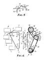
- FIG. 5 a variation of the arrangement of Figure 4 is shown wherein the dam or flange.40 extends from the center of the surface of shell 38 to one end of the shell 38 with another flange 40' also provided.
- Flange 40' joins the flange 40 near the center of the surface of shell 38 and extends to the other end of shell 38 with a trough or conduit 42' provided to direct toner powder collected by the 40' back to the toner hopper 30 ( Figure 3).
- the flange 40 as in the arrangement of Figure 4, has its trough or conduit 32 provided which directs toner powder collected by the flange 40 back to the toner hopper 30.
- FIG 6 another embodiment of apparatus according to the present invention is diagrammatically shown.
- the same reference numerals as used in Figures 1, 2 and 3 are utilized to identify like or similar parts.
- the apparatus of Figure 6 uses a flexible belt receptor member 21 in the portion 1 which utilizes the teachings of United States Patent 3,816,840 to Arthur R. Kotz to produce an unfixed toner powder image at the receptor member 21 in accordance with electrical input signals.
- Portion 2 is an electrophotographic apparatus similar in structure and operation to that described in connection with Figure 2, except that the photoconductive member 10 is provided in flexible belt form.
- the use of the flexible receptor member 21 and the flexible belt type of photoconductive member 10 allows a full frame type of light exposure to be made of an unfused image formed on the flexible receptor member 21 with the resulting light image transferred in full frame form to the photoconductive member 10 via the portion 3 which includes light sources 50 and 51, the reflector 52 for the light sources and lens system 56.
- portion 2 of Figure 6 it differs from the details given for portion 1 shown in Figures 1 and 3 only with respect to the receptor member 21 being in flexible belt form requiring the use of one or more driven rolls, represented at 71-73, to move and direct the receptor member 21 past the toner supply means 24, the stylus electrode 23 and background remover shell 38 and then move the receptor member 21 in its return to the toner supply means 24 so the unfixed toner powder image produced at the electrode 23 will be presented at a flat exposure surface provided by the receptor member 21.
- the apparatus of Figure 6 is operated so that the unfixed image 33 is exposed to light from the lamps 50 and 51 to provide a full frame exposure of the image. Flash tubes are then used for lamps 50 and 51.
- the full frame light image produced by the light exposure of the toner image 33 on the receptor member 21 is passed via the lens system 56 to the photoconductive member 10 of portion 2.
- the photoconductive member 10 unlike the arrangement shown in Figure 2, is provided in flexible belt form and is moved and directed by rolls 64-66, one or more of which are driven, so that it presents a flat exposure surface to the light image provided of the toner image at receptor member 21.
- the portion 2 in Figure 6 has the various functional stations, in addition to the exposure aspect just discussed, which include a development station 13, transfer station 14, fixing station 17, cleaning station 16 and charging station 11. Prior to receiving a light image of an unfixed toner image from the portion 2 at the receptor 21 of portion 1, the photoconductive member 10 receives a uniform electrostatic charge at the charging station 11.
- the uniform electrostatic charge is discharged in accordance with the light image that impinges on the photoconductor 10 when the photoconductor 10 is moved counterclockwise to a position for receiving a light image via the lens system 56.
- the light exposed photoconductor 10 is then presented to the development station where the electrical charge pattern established in accordance with the light image is developed by the deposition of toner powder at the non-light struck areas of the photoconductor 10.
- a receptor member 15, such as paper or other sheet material, is introduced at the transfer station 14 as the developed toner image reaches the transfer station at which point the toner image on the photoconductor 10 is transferred to the receptor member 15.
- the receptor 15, as for Figure 2 is moved to the fixing station 17 of the apparatus where the image is fixed to the receptor member 15 by pressure, heat or a combination of heat and pressure.
- the photoconductor 10 continues to move and is presented to the cleaning station 16 where any toner remaining on the surface of the photoconductor is removed.
- the next station to which the photoconductor is presented is the charging station 11 where the first step in the process, the electrostatic charging of the photoconductor, can be carried out again.
- the receptor member 21 is maintained in the light exposure position until all copies have been made.
- the portion 1 of the apparatus of Figure 6 can be arranged to provide a larger toner image than is desired to be produced by the portion 2 allowing an image to be produced at portion 2that is greater in resolution than the toner image provided by portion 1.
- This requires a lens system 56 thatwill provide a light image at the photoconductor 10 that is a reduction of the light image received from the receptor member 21 and also allows for simplification of the structure needed to provide the electrode styli array at 23.
Landscapes
- Physics & Mathematics (AREA)
- General Physics & Mathematics (AREA)
- Electrophotography Using Other Than Carlson'S Method (AREA)
- Printers Characterized By Their Purpose (AREA)
- Dot-Matrix Printers And Others (AREA)
- Exposure Or Original Feeding In Electrophotography (AREA)
- Combination Of More Than One Step In Electrophotography (AREA)
- Fax Reproducing Arrangements (AREA)
Claims (5)
Applications Claiming Priority (2)
| Application Number | Priority Date | Filing Date | Title |
|---|---|---|---|
| US06/388,583 US4460907A (en) | 1982-06-15 | 1982-06-15 | Electrographic imaging apparatus |
| US388583 | 1982-06-15 |
Publications (2)
| Publication Number | Publication Date |
|---|---|
| EP0096978A1 EP0096978A1 (de) | 1983-12-28 |
| EP0096978B1 true EP0096978B1 (de) | 1986-09-03 |
Family
ID=23534704
Family Applications (1)
| Application Number | Title | Priority Date | Filing Date |
|---|---|---|---|
| EP83302906A Expired EP0096978B1 (de) | 1982-06-15 | 1983-05-20 | Gerät zur elektrographischen Bilderzeugung |
Country Status (5)
| Country | Link |
|---|---|
| US (1) | US4460907A (de) |
| EP (1) | EP0096978B1 (de) |
| JP (1) | JPS593461A (de) |
| CA (1) | CA1193306A (de) |
| DE (1) | DE3365830D1 (de) |
Families Citing this family (50)
| Publication number | Priority date | Publication date | Assignee | Title |
|---|---|---|---|---|
| US4694310A (en) * | 1983-09-19 | 1987-09-15 | Kabushiki Kaisha Toshiba | Method and apparatus of electrophotography |
| US4635074A (en) * | 1986-02-13 | 1987-01-06 | Minnesota Mining And Manufacturing Company | Electrographic stylus recording apparatus |
| US4649402A (en) * | 1986-03-07 | 1987-03-10 | Minnesota Mining And Manufacturing Company | Electrographic stylus recording apparatus |
| US4646112A (en) * | 1986-03-07 | 1987-02-24 | Minnesota Mining And Manufacturing Company | Electrographic stylus recording apparatus |
| US4745418A (en) * | 1986-04-30 | 1988-05-17 | Minnesota Mining And Manufacturing Company | Reusable developing powder composition |
| US4788564A (en) * | 1986-07-10 | 1988-11-29 | Canon Kabushiki Kaisha | Board recording apparatus with reduced smudge |
| JPS6414050A (en) * | 1987-07-08 | 1989-01-18 | Hitachi Ltd | Image recording apparatus and method |
| JPS6449948U (de) * | 1987-09-22 | 1989-03-28 | ||
| JPS6449947U (de) * | 1987-09-22 | 1989-03-28 | ||
| US4877699A (en) * | 1988-08-25 | 1989-10-31 | Eastman Kodak Company | Electrophotographic luminescent amplification process |
| IL105242A0 (en) * | 1993-03-31 | 1993-07-08 | Scitex Corp Ltd | Media exposure system |
| US6025859A (en) * | 1995-12-27 | 2000-02-15 | Sharp Kabushiki Kaisha | Electrostatic printer having an array of optical modulating grating valves |
| US6303986B1 (en) | 1998-07-29 | 2001-10-16 | Silicon Light Machines | Method of and apparatus for sealing an hermetic lid to a semiconductor die |
| US6872984B1 (en) | 1998-07-29 | 2005-03-29 | Silicon Light Machines Corporation | Method of sealing a hermetic lid to a semiconductor die at an angle |
| US6956878B1 (en) | 2000-02-07 | 2005-10-18 | Silicon Light Machines Corporation | Method and apparatus for reducing laser speckle using polarization averaging |
| US7177081B2 (en) | 2001-03-08 | 2007-02-13 | Silicon Light Machines Corporation | High contrast grating light valve type device |
| US6707591B2 (en) | 2001-04-10 | 2004-03-16 | Silicon Light Machines | Angled illumination for a single order light modulator based projection system |
| US6865346B1 (en) | 2001-06-05 | 2005-03-08 | Silicon Light Machines Corporation | Fiber optic transceiver |
| US6782205B2 (en) | 2001-06-25 | 2004-08-24 | Silicon Light Machines | Method and apparatus for dynamic equalization in wavelength division multiplexing |
| US6747781B2 (en) | 2001-06-25 | 2004-06-08 | Silicon Light Machines, Inc. | Method, apparatus, and diffuser for reducing laser speckle |
| US6829092B2 (en) | 2001-08-15 | 2004-12-07 | Silicon Light Machines, Inc. | Blazed grating light valve |
| US6930364B2 (en) | 2001-09-13 | 2005-08-16 | Silicon Light Machines Corporation | Microelectronic mechanical system and methods |
| US6956995B1 (en) | 2001-11-09 | 2005-10-18 | Silicon Light Machines Corporation | Optical communication arrangement |
| US6800238B1 (en) | 2002-01-15 | 2004-10-05 | Silicon Light Machines, Inc. | Method for domain patterning in low coercive field ferroelectrics |
| US6728023B1 (en) | 2002-05-28 | 2004-04-27 | Silicon Light Machines | Optical device arrays with optimized image resolution |
| US6767751B2 (en) | 2002-05-28 | 2004-07-27 | Silicon Light Machines, Inc. | Integrated driver process flow |
| US7054515B1 (en) | 2002-05-30 | 2006-05-30 | Silicon Light Machines Corporation | Diffractive light modulator-based dynamic equalizer with integrated spectral monitor |
| US6822797B1 (en) | 2002-05-31 | 2004-11-23 | Silicon Light Machines, Inc. | Light modulator structure for producing high-contrast operation using zero-order light |
| US6829258B1 (en) | 2002-06-26 | 2004-12-07 | Silicon Light Machines, Inc. | Rapidly tunable external cavity laser |
| US6714337B1 (en) | 2002-06-28 | 2004-03-30 | Silicon Light Machines | Method and device for modulating a light beam and having an improved gamma response |
| US6813059B2 (en) | 2002-06-28 | 2004-11-02 | Silicon Light Machines, Inc. | Reduced formation of asperities in contact micro-structures |
| US6908201B2 (en) | 2002-06-28 | 2005-06-21 | Silicon Light Machines Corporation | Micro-support structures |
| US6801354B1 (en) | 2002-08-20 | 2004-10-05 | Silicon Light Machines, Inc. | 2-D diffraction grating for substantially eliminating polarization dependent losses |
| US7057795B2 (en) | 2002-08-20 | 2006-06-06 | Silicon Light Machines Corporation | Micro-structures with individually addressable ribbon pairs |
| US6712480B1 (en) | 2002-09-27 | 2004-03-30 | Silicon Light Machines | Controlled curvature of stressed micro-structures |
| US6928207B1 (en) | 2002-12-12 | 2005-08-09 | Silicon Light Machines Corporation | Apparatus for selectively blocking WDM channels |
| US7057819B1 (en) | 2002-12-17 | 2006-06-06 | Silicon Light Machines Corporation | High contrast tilting ribbon blazed grating |
| US6987600B1 (en) | 2002-12-17 | 2006-01-17 | Silicon Light Machines Corporation | Arbitrary phase profile for better equalization in dynamic gain equalizer |
| US6934070B1 (en) | 2002-12-18 | 2005-08-23 | Silicon Light Machines Corporation | Chirped optical MEM device |
| US6927891B1 (en) | 2002-12-23 | 2005-08-09 | Silicon Light Machines Corporation | Tilt-able grating plane for improved crosstalk in 1×N blaze switches |
| US7068372B1 (en) | 2003-01-28 | 2006-06-27 | Silicon Light Machines Corporation | MEMS interferometer-based reconfigurable optical add-and-drop multiplexor |
| US7286764B1 (en) | 2003-02-03 | 2007-10-23 | Silicon Light Machines Corporation | Reconfigurable modulator-based optical add-and-drop multiplexer |
| US6947613B1 (en) | 2003-02-11 | 2005-09-20 | Silicon Light Machines Corporation | Wavelength selective switch and equalizer |
| US6922272B1 (en) | 2003-02-14 | 2005-07-26 | Silicon Light Machines Corporation | Method and apparatus for leveling thermal stress variations in multi-layer MEMS devices |
| US7391973B1 (en) | 2003-02-28 | 2008-06-24 | Silicon Light Machines Corporation | Two-stage gain equalizer |
| US6806997B1 (en) | 2003-02-28 | 2004-10-19 | Silicon Light Machines, Inc. | Patterned diffractive light modulator ribbon for PDL reduction |
| US6922273B1 (en) | 2003-02-28 | 2005-07-26 | Silicon Light Machines Corporation | PDL mitigation structure for diffractive MEMS and gratings |
| US7027202B1 (en) | 2003-02-28 | 2006-04-11 | Silicon Light Machines Corp | Silicon substrate as a light modulator sacrificial layer |
| US6829077B1 (en) | 2003-02-28 | 2004-12-07 | Silicon Light Machines, Inc. | Diffractive light modulator with dynamically rotatable diffraction plane |
| US7042611B1 (en) | 2003-03-03 | 2006-05-09 | Silicon Light Machines Corporation | Pre-deflected bias ribbons |
Family Cites Families (10)
| Publication number | Priority date | Publication date | Assignee | Title |
|---|---|---|---|---|
| US3343142A (en) * | 1963-01-02 | 1967-09-19 | Xerox Corp | Xerographic coding and information storage on a specular business machine card |
| GB1230022A (de) * | 1968-11-14 | 1971-04-28 | ||
| US3816840A (en) * | 1973-04-20 | 1974-06-11 | Minnesota Mining & Mfg | Electrographic recording process and apparatus using conductive toner subject to a capacitive force |
| US4046471A (en) * | 1975-11-03 | 1977-09-06 | International Business Machines Corporation | Dual mode electrophotographic apparatus having dual function printing beam |
| US4124286A (en) * | 1977-08-18 | 1978-11-07 | Burroughs Corporation | Method and apparatus for xerographically printing a composite record of fixed and variable data |
| JPS5454041A (en) * | 1977-10-07 | 1979-04-27 | Ricoh Co Ltd | Compliex image formation |
| US4167324A (en) * | 1977-10-17 | 1979-09-11 | Burroughs Corporation | Apparatus for xerographically printing a composite record based on fixed and variable data |
| JPS5489737A (en) * | 1977-12-27 | 1979-07-17 | Ricoh Co Ltd | Copying machine |
| CA1142996A (en) * | 1979-03-22 | 1983-03-15 | George W. Fabel | Electrographic recording method and apparatus |
| GB2063158B (en) * | 1979-11-16 | 1983-08-10 | Gestetner Mfg Ltd | Copying method and apparatus |
-
1982
- 1982-06-15 US US06/388,583 patent/US4460907A/en not_active Expired - Fee Related
-
1983
- 1983-05-16 CA CA000428212A patent/CA1193306A/en not_active Expired
- 1983-05-20 DE DE8383302906T patent/DE3365830D1/de not_active Expired
- 1983-05-20 EP EP83302906A patent/EP0096978B1/de not_active Expired
- 1983-06-14 JP JP58105091A patent/JPS593461A/ja active Pending
Also Published As
| Publication number | Publication date |
|---|---|
| EP0096978A1 (de) | 1983-12-28 |
| JPS593461A (ja) | 1984-01-10 |
| CA1193306A (en) | 1985-09-10 |
| DE3365830D1 (en) | 1986-10-09 |
| US4460907A (en) | 1984-07-17 |
Similar Documents
| Publication | Publication Date | Title |
|---|---|---|
| US4460907A (en) | Electrographic imaging apparatus | |
| US3011473A (en) | Xerographic apparatus | |
| US4287850A (en) | Magnetic brush developing apparatus | |
| US4432631A (en) | Photoconductor charging technique | |
| US3882822A (en) | Apparatus for Developing Electrostatic Latent Images | |
| US4136637A (en) | Continuous contrast development system | |
| US5157226A (en) | Developing apparatus producing toner powder cloud for developing images | |
| US3532494A (en) | Solid area development in xerography employing an insulating screen in the charging step | |
| US4585326A (en) | Developing electrophotographic image using magnets and magnetic material | |
| US4527886A (en) | Electrophotographic recording apparatus having both functions of copying and printing | |
| CA1230915A (en) | Method and apparatus of electrophotography | |
| CA1223297A (en) | Xerographic apparatus and process with backside photoconductor imaging | |
| US5488465A (en) | Electrophotographic developing method using magnetic developing material and apparatus employed therefor | |
| US4373799A (en) | Multi-mode electrostatographic printing machine | |
| US5140373A (en) | Electrostatic latent image developing apparatus with bristle height adjusting member | |
| EP0416895B1 (de) | Elektrostatografisches Gerät | |
| US5148225A (en) | Electrophotographic process and apparatus | |
| US4770967A (en) | Method and apparatus for the development of an electrostatic charge image | |
| US3767446A (en) | Development method with oscillating brush pad | |
| CA1038015A (en) | Color electrophotographic printing machine | |
| JPS6064364A (ja) | 画像形成方法および装置 | |
| CA1052559A (en) | Magnetic brush developing apparatus | |
| GB2176025A (en) | Electrophotographic process | |
| JPS61219066A (ja) | 現像装置 | |
| CA1140201A (en) | Multi-mode electrostatographic printing machine |
Legal Events
| Date | Code | Title | Description |
|---|---|---|---|
| PUAI | Public reference made under article 153(3) epc to a published international application that has entered the european phase |
Free format text: ORIGINAL CODE: 0009012 |
|
| AK | Designated contracting states |
Designated state(s): CH DE FR GB IT LI NL |
|
| 17P | Request for examination filed |
Effective date: 19840601 |
|
| GRAA | (expected) grant |
Free format text: ORIGINAL CODE: 0009210 |
|
| ITF | It: translation for a ep patent filed | ||
| AK | Designated contracting states |
Kind code of ref document: B1 Designated state(s): CH DE FR GB IT LI NL |
|
| REF | Corresponds to: |
Ref document number: 3365830 Country of ref document: DE Date of ref document: 19861009 |
|
| ET | Fr: translation filed | ||
| PGFP | Annual fee paid to national office [announced via postgrant information from national office to epo] |
Ref country code: NL Payment date: 19870531 Year of fee payment: 5 |
|
| PLBE | No opposition filed within time limit |
Free format text: ORIGINAL CODE: 0009261 |
|
| STAA | Information on the status of an ep patent application or granted ep patent |
Free format text: STATUS: NO OPPOSITION FILED WITHIN TIME LIMIT |
|
| 26N | No opposition filed | ||
| PGFP | Annual fee paid to national office [announced via postgrant information from national office to epo] |
Ref country code: DE Payment date: 19890426 Year of fee payment: 7 |
|
| PG25 | Lapsed in a contracting state [announced via postgrant information from national office to epo] |
Ref country code: GB Effective date: 19890520 |
|
| PG25 | Lapsed in a contracting state [announced via postgrant information from national office to epo] |
Ref country code: LI Effective date: 19890531 Ref country code: CH Effective date: 19890531 |
|
| REG | Reference to a national code |
Ref country code: GB Ref legal event code: 732 |
|
| PG25 | Lapsed in a contracting state [announced via postgrant information from national office to epo] |
Ref country code: NL Effective date: 19891201 |
|
| NLV4 | Nl: lapsed or anulled due to non-payment of the annual fee | ||
| GBPC | Gb: european patent ceased through non-payment of renewal fee | ||
| PG25 | Lapsed in a contracting state [announced via postgrant information from national office to epo] |
Ref country code: FR Free format text: LAPSE BECAUSE OF NON-PAYMENT OF DUE FEES Effective date: 19900131 |
|
| REG | Reference to a national code |
Ref country code: CH Ref legal event code: PL |
|
| REG | Reference to a national code |
Ref country code: FR Ref legal event code: ST |
|
| PG25 | Lapsed in a contracting state [announced via postgrant information from national office to epo] |
Ref country code: DE Effective date: 19910201 |