EP0097026A1 - Machine de cardage - Google Patents
Machine de cardage Download PDFInfo
- Publication number
- EP0097026A1 EP0097026A1 EP83303327A EP83303327A EP0097026A1 EP 0097026 A1 EP0097026 A1 EP 0097026A1 EP 83303327 A EP83303327 A EP 83303327A EP 83303327 A EP83303327 A EP 83303327A EP 0097026 A1 EP0097026 A1 EP 0097026A1
- Authority
- EP
- European Patent Office
- Prior art keywords
- trough
- carding engine
- frame
- secured
- front member
- Prior art date
- Legal status (The legal status is an assumption and is not a legal conclusion. Google has not performed a legal analysis and makes no representation as to the accuracy of the status listed.)
- Ceased
Links
Images

Classifications
-
- D—TEXTILES; PAPER
- D01—NATURAL OR MAN-MADE THREADS OR FIBRES; SPINNING
- D01G—PRELIMINARY TREATMENT OF FIBRES, e.g. FOR SPINNING
- D01G15/00—Carding machines or accessories; Card clothing; Burr-crushing or removing arrangements associated with carding or other preliminary-treatment machines
- D01G15/02—Carding machines
- D01G15/12—Details
- D01G15/32—Framework; Casings; Coverings
Definitions
- This invention relates to carding engines.
- covers suitably secured to the side frames.
- Covers previously used have been constructed from a large number of different sections with no inherent rigidity, the sections being supported on brackets extending from the carding engine frame.
- the bracket systems required have been complex and the removal of large numbers of bolts, brackets and other fastening members have made the complete stripping down of the side of a carding engine a difficult and time-consuming operation. Even to gain access to restricted small areas of the side of a carding engine has presented considerable difficulties.
- the object of the present invention is considerably to simplify the carding engine side cover structure and to improve access through that cover structure.
- a carding engine has a frame that includes side frames between which are rotatably mounted the main carding cylinder and other rollers of the carding engine, and each side frame is covered by a cover assembly comprising an open fronted trough extending longitudinally of the carding engine and having a rear part secured to the frame, end covers secured to the trough at opposite ends thereof and a front member extending between the end covers and secured thereto.
- each cover assembly total as few as four in number and their only fixed connection to the frame is by way of the rear part of the trough.
- the other main elements of each cover assembly are merely secured one to another and there is no direct fixed connection between them and the frame at the respective side of the card.
- brackets and fastenings between each cover assembly and the carding engine frame are avoided.
- Use of a small number of main elements for the cover assembly allows rapid stripping down and reassembly and thus leads to shorter maintenance down times for the carding engine. It also reduces loss or damage which can occur when a cover assembly is formed from a multiplicity of smaller parts.
- the trough, end covers and front member when secured together form a box-like structure, which has good resistance to bending forces.
- the only additional bracing or support of the assembly that is needed is support against torsional forces and further simplification is gained.
- Such an arrangement may be achieved by fabricating the cover sections from sheet metal and by bolting together flange sections of the fabrications.
- two parallel plates extend inwardly longitudinally of the trough from the upper rear part of each end cover to form a dip arrangement for engaging around opposite sides of a part of the frame.
- the clip arrangements When engaged around the frame parts the clip arrangements give the necessary degree of torsional rigidity to the assembled cover.
- the trough of the cover assembly may be formed as a single unit or may be made up of sections bolted together. Forming the rear wall and the base separately and bolting them together is particularly advantageous as this simplifies fabrication of the trough.
- a complete cover assembly also requires means closing the whole of the front of the cover if the front member does not itself do this. Where a separate front cover is required this is preferably in the form of one or more doors removably mounted on the front member.
- a single door is provided which closes the whole of the front of the cover assembly, the door extending from one end cover to the other and extending from the front member at the upper part of the cover assembly to a front part of the trough at the lower part of the cover assembly. Provision of a single door in this way enhances immediate access to the interior of the whole of the cover assembly and thus to the whole of the drive means and other components that are generally shielded by the cover assembly.
- a rear wall of the trough is desirably formed with an access opening in at least the longitudinally central region thereof.
- the access opening should preferably be of such a size that a cylinder screen may pass therethrough.
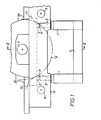
- the drawings show the frame structure and cover assembly at only one side of the carding engine, it being understood that at the other side of the carding engine the basic structure is similar and of opposite hand.
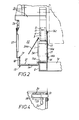
- the carding engine includes a floor engaging sub-frame comprising two U-shaped assemblies each comprising two uprights 1 joined by a horizontal beam 1a, the two assemblies being joined by parallel horizontal beams 2.
- Each upright 1 terminates in an upper post 3 supporting a pivot bearing 4 on which is supported by bearing pads 5 a side frame 6 of the carding engine, the side frame being of any suitable construction.
- the side frame 6 supports a bearing schematically indicated as 7 for a main carding cylinder, part of which is shown in outline at 8, the cylinder extending between the two side frames and tying those frame members together.
- the side frames also support bearing assemblies 9 and 10 for takerin and doffer members indicated in outline at 11 and 12 respectively. It will be seen that each side frame 6 is allowed by the pivot bearing 4 a degree of universal swivelling movement relative to the sub-frame, so freeing the side frames from stress transmission.
- the cover assembly at each side of the carding engine comprises an open fronted trough shown generally as 13 which extends longitudinally the full length of the carding engine.
- the trough has a base 14, cut away at 15 to accommodate the uprights 1, and with a stepped central section 15a fitting over the respective beam 2.
- a rear wall of the trough is formed by part 16 integral with the base and part 16a secured by bolts 16b to the part 16 and extending upwardly behind the uprights 1.
- the rear wall is secured to each of the uprights by bolts 17 passing through holes 17a in part 16a.
- the upper edge of the rear wall is restrained by one or more clips 16c secured to the side frame 6.
- the trough also has a front wall 18 with a turned in lip 19. Inturned flanges 20, 21 are formed around the whole of each end of the trough.
- the cover assembly includes end covers 22, one at each end of the assembly, each end cover having an outer surface 23 from which projects an inturned lip 24 terminating in a further inturned flange 25 extending parallel to the plate 23 and around the full periphery of the end cover.
- the flanges 20, 21 of the trough and the flanges 25 of the two end covers are formed with mating holes by way of which the end covers may be bolted to the trough.
- a top front bar 26 also extends the full length of the carding engine and has end flanges again formed with holes by way of which each end of the bar may be bolted to the upper part of the flange 25 of the adjacent end cover.
- each end cover 22 is formed with a U-shaped clip arrangement 22a formed by two parallel plates extending inwardly longitudinally of the trough from the upper rear part of the end cover.
- Each clip arrangement 22a embraces part of the end of the side frame 6 to restrain the cover assembly against movement transversely of the side frame member and thus give torsional rigidity. No bolted connection is made as it is necessary for there to be some freedom for relative movement between the side frame 6 and the cover assembly.
- the cover assembly includes a single door 27 (not shown in Figure 3) which extends the full length of the carding engine between the two end covers 22 and which also extends the full height from the top member 26 to the top of the front wall 18 of the trough.
- the door 27 is secured at each of the top corners by a hinge arrangement.
- the lower edge of the door may be secured to the cover assembly by a suitable lock.
- the hinge arrangement at one side of the door may comprise a bolt supported in a holder 29 that is secured to the door and spring biased by a compression spring 30 into a locking position wherein the bolt engages in a hole in a plate 31 secured to the respective end cover 22.
- the bolt has a handle 32 by way of which the bolt may be disengaged.
- the hinge at the other side may be similar, or may be a simple axially separable hinge. By disengaging the bolts and separating the other hinge the door may rapidly be completely removed. Access is thus gained to the interior of the cover assembly and thus to the frame of the carding engine and to the drive assembly and other elements that may be located within the cover assembly.
- the rear wall 16a of the trough is formed with an opening 33 having a surrounding guard 34 to which is pivoted an inspection cover 34a. The opening leads to the undercard region below the main carding cylinder and is desirably sufficiently large to allow passage of a cylinder screen therethrough.
- top cover which is independent of the cover assembly and is integral with the outer top cover assembly 35 for the main cylinder and its cooperating flat assembly.
- the elements of the cover assembly are desirably fabricated from sheet metal and are formed so as to fit around the frame structure of the particular carding engine to be covered. They are also formed with the bolt holes required to assemble the parts of the cover, and also with locating and mounting holes for other parts of the carding engine that may be housed within the cover assembly. These will particularly be openings in the rear wall parts 16 and 16a, not shown in the drawing as they may be planned so as to suit any required carding engine layout.
- the simplicity of the construction, the rigidity of the finished assembly and the use of only four bolts to secure the assembly to the frame of the carding engine lead to enormous advantages when access needs to be gained to the side of the carding engine for maintenance purposes.
Landscapes
- Engineering & Computer Science (AREA)
- Textile Engineering (AREA)
- Preliminary Treatment Of Fibers (AREA)
Applications Claiming Priority (2)
| Application Number | Priority Date | Filing Date | Title |
|---|---|---|---|
| GB8217131 | 1982-06-12 | ||
| GB8217131 | 1982-06-12 |
Publications (1)
| Publication Number | Publication Date |
|---|---|
| EP0097026A1 true EP0097026A1 (fr) | 1983-12-28 |
Family
ID=10531008
Family Applications (1)
| Application Number | Title | Priority Date | Filing Date |
|---|---|---|---|
| EP83303327A Ceased EP0097026A1 (fr) | 1982-06-12 | 1983-06-08 | Machine de cardage |
Country Status (2)
| Country | Link |
|---|---|
| EP (1) | EP0097026A1 (fr) |
| JP (1) | JPS5966521A (fr) |
Citations (3)
| Publication number | Priority date | Publication date | Assignee | Title |
|---|---|---|---|---|
| US2912721A (en) * | 1953-08-03 | 1959-11-17 | Mullenschlader Carl Otto | Carding machines |
| CH381129A (it) * | 1961-08-23 | 1964-08-14 | Bettoni Ezio | Carda per fibre tessili |
| US4280250A (en) * | 1979-07-26 | 1981-07-28 | Platt Saco Lowell Limited | Textile carding machine frame construction |
-
1983
- 1983-06-08 EP EP83303327A patent/EP0097026A1/fr not_active Ceased
- 1983-06-13 JP JP10435783A patent/JPS5966521A/ja active Pending
Patent Citations (3)
| Publication number | Priority date | Publication date | Assignee | Title |
|---|---|---|---|---|
| US2912721A (en) * | 1953-08-03 | 1959-11-17 | Mullenschlader Carl Otto | Carding machines |
| CH381129A (it) * | 1961-08-23 | 1964-08-14 | Bettoni Ezio | Carda per fibre tessili |
| US4280250A (en) * | 1979-07-26 | 1981-07-28 | Platt Saco Lowell Limited | Textile carding machine frame construction |
Also Published As
| Publication number | Publication date |
|---|---|
| JPS5966521A (ja) | 1984-04-16 |
Similar Documents
| Publication | Publication Date | Title |
|---|---|---|
| KR102251608B1 (ko) | 전자 캐비닛 | |
| US9510471B2 (en) | Electronics cabinet | |
| FI97712C (fi) | Moottoriajoneuvon moottoriosan kate | |
| US6494779B1 (en) | Control cabinet with cooling device | |
| US20040020873A1 (en) | Earthquake resistant equipment rack | |
| EP1043182B1 (fr) | Module de portiere | |
| EP2925106A1 (fr) | Structure modulaire autonome pouvant contenir des dispositifs électroniques de puissance et autres dispositifs électriques | |
| HU223729B1 (hu) | Szekrényváz, különösen elektromos berendezésekhez | |
| JPH04229004A (ja) | 低電圧用電気開閉装置キャビネット | |
| DE202006021103U1 (de) | Wäschetrockenmaschine | |
| US11840279B2 (en) | Secondary retention devices for retaining a heavy equipment cab on a frame | |
| US4003610A (en) | Terminal housing | |
| US4785900A (en) | Vehicle compartment closure arrangement | |
| CA1251985A (fr) | Systeme de filtration d'air pour cabine de moissonneuse | |
| EP1358702B1 (fr) | Ensemble et procede pour construire une armoire electrique destinee a l'exterieur | |
| US5388424A (en) | Composite cover for transport refrigeration unit | |
| US4700517A (en) | Cabin-like cover | |
| US4134624A (en) | Framing unit for a plurality of rectangular structures | |
| US4073591A (en) | Composite U Joint guard-step | |
| JP7289682B2 (ja) | 床下装置 | |
| EP0450347A1 (fr) | Cadre porteur pour baignoires dites whirl-pool | |
| JPS6021336Y2 (ja) | フオ−クリフトのエンジンカバ−構造 | |
| CN216429255U (zh) | 一种核电厂临时围挡 | |
| JP2857549B2 (ja) | 板金製ルーフ | |
| US5131699A (en) | Locking device |
Legal Events
| Date | Code | Title | Description |
|---|---|---|---|
| PUAI | Public reference made under article 153(3) epc to a published international application that has entered the european phase |
Free format text: ORIGINAL CODE: 0009012 |
|
| AK | Designated contracting states |
Designated state(s): CH DE FR GB IT LI |
|
| 17P | Request for examination filed |
Effective date: 19840622 |
|
| STAA | Information on the status of an ep patent application or granted ep patent |
Free format text: STATUS: THE APPLICATION HAS BEEN REFUSED |
|
| 18R | Application refused |
Effective date: 19851024 |
|
| RIN1 | Information on inventor provided before grant (corrected) |
Inventor name: RIMMER, MICHAEL JACK Inventor name: VARGA, JOHN MAXIMILIAN JULES |