EP0097034B1 - Druckfixierer - Google Patents
Druckfixierer Download PDFInfo
- Publication number
- EP0097034B1 EP0097034B1 EP83303350A EP83303350A EP0097034B1 EP 0097034 B1 EP0097034 B1 EP 0097034B1 EP 83303350 A EP83303350 A EP 83303350A EP 83303350 A EP83303350 A EP 83303350A EP 0097034 B1 EP0097034 B1 EP 0097034B1
- Authority
- EP
- European Patent Office
- Prior art keywords
- pressure
- roller
- fuser
- backup
- roll
- Prior art date
- Legal status (The legal status is an assumption and is not a legal conclusion. Google has not performed a legal analysis and makes no representation as to the accuracy of the status listed.)
- Expired
Links
- 239000000758 substrate Substances 0.000 claims description 5
- 238000009877 rendering Methods 0.000 claims description 3
- 239000002245 particle Substances 0.000 description 16
- 239000000463 material Substances 0.000 description 10
- 239000000835 fiber Substances 0.000 description 9
- 239000000843 powder Substances 0.000 description 8
- 238000004140 cleaning Methods 0.000 description 6
- 230000008859 change Effects 0.000 description 4
- 238000007599 discharging Methods 0.000 description 4
- 239000008187 granular material Substances 0.000 description 4
- 230000033001 locomotion Effects 0.000 description 4
- 230000003287 optical effect Effects 0.000 description 4
- 230000002411 adverse Effects 0.000 description 3
- 238000000034 method Methods 0.000 description 3
- 229910000831 Steel Inorganic materials 0.000 description 2
- XAGFODPZIPBFFR-UHFFFAOYSA-N aluminium Chemical compound [Al] XAGFODPZIPBFFR-UHFFFAOYSA-N 0.000 description 2
- 229910052782 aluminium Inorganic materials 0.000 description 2
- 238000011161 development Methods 0.000 description 2
- 230000018109 developmental process Effects 0.000 description 2
- 230000003134 recirculating effect Effects 0.000 description 2
- 239000010959 steel Substances 0.000 description 2
- 239000012815 thermoplastic material Substances 0.000 description 2
- 230000037303 wrinkles Effects 0.000 description 2
- 229910000838 Al alloy Inorganic materials 0.000 description 1
- 230000009471 action Effects 0.000 description 1
- 238000003491 array Methods 0.000 description 1
- 238000005452 bending Methods 0.000 description 1
- 230000008901 benefit Effects 0.000 description 1
- 230000006835 compression Effects 0.000 description 1
- 238000007906 compression Methods 0.000 description 1
- 239000000470 constituent Substances 0.000 description 1
- 238000001816 cooling Methods 0.000 description 1
- 239000005357 flat glass Substances 0.000 description 1
- 239000006260 foam Substances 0.000 description 1
- -1 for example Substances 0.000 description 1
- 239000011521 glass Substances 0.000 description 1
- 239000003365 glass fiber Substances 0.000 description 1
- 150000002500 ions Chemical class 0.000 description 1
- 239000000696 magnetic material Substances 0.000 description 1
- 230000007246 mechanism Effects 0.000 description 1
- 238000012986 modification Methods 0.000 description 1
- 230000004048 modification Effects 0.000 description 1
- 239000013307 optical fiber Substances 0.000 description 1
- AJCDFVKYMIUXCR-UHFFFAOYSA-N oxobarium;oxo(oxoferriooxy)iron Chemical compound [Ba]=O.O=[Fe]O[Fe]=O.O=[Fe]O[Fe]=O.O=[Fe]O[Fe]=O.O=[Fe]O[Fe]=O.O=[Fe]O[Fe]=O.O=[Fe]O[Fe]=O AJCDFVKYMIUXCR-UHFFFAOYSA-N 0.000 description 1
- 229920003217 poly(methylsilsesquioxane) Polymers 0.000 description 1
- 239000011148 porous material Substances 0.000 description 1
- 230000008569 process Effects 0.000 description 1
- 238000012545 processing Methods 0.000 description 1
- 230000004044 response Effects 0.000 description 1
- 238000013000 roll bending Methods 0.000 description 1
- 239000007787 solid Substances 0.000 description 1
- 238000007711 solidification Methods 0.000 description 1
- 230000008023 solidification Effects 0.000 description 1
- 239000007921 spray Substances 0.000 description 1
- 239000010935 stainless steel Substances 0.000 description 1
- 229910001220 stainless steel Inorganic materials 0.000 description 1
- 229920003002 synthetic resin Polymers 0.000 description 1
- 239000000057 synthetic resin Substances 0.000 description 1
- 238000012546 transfer Methods 0.000 description 1
- WFKWXMTUELFFGS-UHFFFAOYSA-N tungsten Chemical compound [W] WFKWXMTUELFFGS-UHFFFAOYSA-N 0.000 description 1
- 229910052721 tungsten Inorganic materials 0.000 description 1
- 239000010937 tungsten Substances 0.000 description 1
- 230000000007 visual effect Effects 0.000 description 1
- 239000002699 waste material Substances 0.000 description 1
Images


Classifications
-
- G—PHYSICS
- G03—PHOTOGRAPHY; CINEMATOGRAPHY; ANALOGOUS TECHNIQUES USING WAVES OTHER THAN OPTICAL WAVES; ELECTROGRAPHY; HOLOGRAPHY
- G03G—ELECTROGRAPHY; ELECTROPHOTOGRAPHY; MAGNETOGRAPHY
- G03G15/00—Apparatus for electrographic processes using a charge pattern
- G03G15/20—Apparatus for electrographic processes using a charge pattern for fixing, e.g. by using heat
- G03G15/2092—Apparatus for electrographic processes using a charge pattern for fixing, e.g. by using heat using pressure only
Definitions
- This invention relates to pressure fusers particularly for use in xerographic copying apparatus for the fixing of particulate thermoplastic material arranged in image configuration by passing the substrate carrying the images between a pair of unheated pressure engaged roll members forming part of a three roll pressure fuser.
- a light image of an original to be copied is typically recorded in the form of a latent electrostatic image upon a photosensitive member with subsequent rendering of the latent image visible by the application of particulate thermoplastic material, commonly referred to as toner.
- the visual toner image can be either fixed directly upon the photosensitive member or transferred from the member to another support, such as a sheet of plain paper, with subsequent affixing of the image thereto, the most common method of affixing comprising the simultaneous application of heat and pressure.
- Three-roll systems where the nip is formed by two parallel rolls also have an advantage over two-roll systems in that once they are set up using one size paper they can accommodate various size papers.
- a change in paper size results in a change in load distribution which results in a change in deflection of each roll in the opposite direction.
- Edge wear is the wear on the pressure roll where it is contacted by the edges of the skewed roller. Edge wear is caused by the loading forces exerted at the edges of the skewed roll where they contact the pressure roll. Thus, due to the forces exerted by the edges of the skewed loading roll on the pressure roller it becomes grooved. Since the grooves are well within the paper path these grooves adversely affect the final copy.
- a pressure fuser having the features recited in the pre-characterizing portion of claim 1 below is known from GB-A-1 585 720.
- a pressure fuser according to the present invention is intended to solve both the above mentioned problems, and has the backup roller overskewed with respect to the axes of said fuser and pressure rollers such that the tone distribution between said backup roller and said pressure roller is a maximum at the centre of said backup roller and zero at its ends.
- overskewed is meant that the axis of the last- mentioned roll is angulated with respect to the axes of the other rolls such that the pressure exerted between the overskewed roll and the pressure roll is graduated from the centre of the roll outwardly along its axis and, in this case, such that there is a peak force at the centre and zero force at the ends.
- a preferred feature is the provision of unloading structure for removing the nip pressure between the fuser and pressure rollers to thereby facilitate paper jam clearance.
- Figure 1 schematically depicts the various components of an electrophotographic printing machine incorporating a fuser of the present invention. It will become evident from the following discussion that these features are equally well suited for use in a wide variety of electrostato- graphic printing machines, and are not necessarily limited in their application to the particular embodiment depicted herein.
- the electrophotographic printing machine employs a belt 10 having a photoconductive surface deposited on a conductive substrate.
- the photoconductive surface is made from an organic photoconductor with the conductive substrate being made from an aluminum alloy.
- Belt 10 moves in the direction of arrow 12 to advance successive portions of the photoconductive surface through the various processing stations disposed adjacent the path of movement thereof.
- Rollers 14, 16 and 18 maintain belt 10 under suitable tension.
- Roller 14 is coupled to drive motor 20.
- Rollers 16 and 18 are mounted in suitable bearings to rotate freely and act as idler rollers.
- Motor 20 drives roller 14 to advance belt 10 in the direction of arrow 12.
- An original document 22 is disposed facedown upon a transparent platen 24.
- Platen 24 is mounted in a frame 26 which is capable of reciprocating motion in a horizontal plane as indicated by arrow 27.
- Belt 10 is driven at a linear velocity substantially equal to the linear velocity of platen 24.
- Belt 10 moves in a recirculating path. In order to reproduce a copy of an original document, belt 10 performs two complete cycles of movement through the recirculating path.
- Charging-transferring unit 28 includes a corona generating device 30 which charges the photoconductive surface of belt 20 to a relatively high substantially uniform potential.
- Corona generating device 30 includes a U-shaped shield 32 having an open end facing the photoconductive surface of belt 10. Two rows of substantially equally spaced pins 34 are supported such that they extend outwardly from shield 32 toward the open end thereof.
- Combined exposing-discharging unit 36 includes a light source 38, preferably an elongated tungsten lamp.
- Light source 38 is disposed stationarily beneath platen 24.
- An opaque shield 40 surrounds light source 38.
- Shield 40 has a slit therein so that the light rays from light source 38 are projected onto original document 22 disposed facedown on transparent platen 24. As platen 24 moves to the left as viewed in Figure 1, successive incremental portions of original document 22 are illuminated. Light rays reflected from original document 22 are transmitted through a bundle of image transmitting fibers, indicated generally by the reference numeral 42.
- Image transmitting fibers 42 are bundled gradient index optical fibers.
- US-A-3,658,407 issued to Kitano et al in 1972 describes a light conducting fiber made of glass or synthetic resin which has a refractive index distribution in cross section thereof that varies consecutively and parabolically outwardly from a center portion thereof. Each fiber acts as a focusing lens to transmit part of an image placed at, or near, one end thereof.
- An assembly of fibers, in a staggered two-row array, transmits and focuses a complete image of the object.
- the fiber lenses are produced under the tradename "SELFOC"; the mark is registered in Japan and owned by Nippon Sheet Glass Company, Limited.
- gradient index lens arrays are used as a replacement for conventional optical systems in electrophotographic printing machines, such use being disclosed in US-A-3,947,106 issued to Hamaguchi et al in 1976 and US-A-3,977,777 issued to Tanaka et al in 1976.
- the relevant portions of the foregoing patents are hereby incorporated into the present disclosure.
- the light rays reflected from the original document form a light image which are transmitted through the image transmitting fibers onto the charged portions of the photoconductive surface of belt 10 to dissipate the charge thereon in accordance with the pattern of the light image.
- This records an electrostatic latent image on the photoconductive surface of belt 10 which corresponds to the informational areas contained within original document 22.
- Combined exposing-discharging unit 36 also includes a light transmitting glass fiber optical tube 44.
- One end of optical tube 44 is disposed closely adjacent to light source 38.
- the other end of optical tube 44 is positioned closely adjacent to the photoconductive surface of belt 10 prior to combined charging-transferring unit 28 in the direction of movement of belt 10, as indicated by arrow 12.
- Combined developing-cleaning unit 46 includes a developer roller, indicated generally by the reference numeral 48.
- Developer roller 48 comprises an elongated cylindrical magnet 52 mounted interiorly of tubular member 50.
- Tubular member 50 rotates in the direction of arrow 54.
- Voltage source 56 is electrically connected to annular member 50 so as to electrically bias tubular member 50 to a potential ranging from about 50 volts to about 500 volts.
- a specific selected voltage level depends upon the potential level of the latent image and that of the background areas. During development, the biasing voltage is intermediate that of the background and latent image.
- Conveyor 58 which comprises a cylindrical member 60 having a plurality of buckets 62 thereon advances developer material comprising magnetic carrier granules having toner particles adhering triboelectrically thereto upwardly to developer roller 48.
- Developer roller 48 attracts the developer material thereto.
- tubular member 50 rotates in the direction of arrow 54. The developer material is transported into contact with the latent image and toner particles are attracted from the carrier granules thereto. In this way, a toner powder image is formed on the photoconductive surface of belt 10.
- Auger 64 mixes the toner particles with the carrier granules.
- tubular member 50 is made from a non-magnetic material such as aluminum having the exterior circumferential surface thereof roughened.
- Magnetic member 52 is made preferably from barium ferrite having a plurality of magnetic poles pressed thereon.
- a metering blade may be employed to define a gap between tubular member 50 through which the developer material passes. This gap regulates the quantity of developer material being transported into contact with the electrostatic latent image recorded on the photoconductive surface of belt 10.
- sheet feeder 68 includes a rotatably mounted cylinder having a plurality of spaced, flexible vanes extending outwardly therefrom. The free end of each vane successively engages the uppermost sheet 66 of stack 70. As feeder 68 rotates, sheet 66 moves into chute 72. Registration roller 74 advances sheet 66, in synchronism with the toner powder image on the photoconductive surface of belt 10, to combined charging-transferring unit 28.
- Corona generating device 30 of combined charging-transferring unit 28 sprays ions onto the backside of the copy sheet. This attracts the toner powder image from the photoconductive surface of belt 10 to the sheet. After transfer, the sheet continues to move with belt 10 until the beam strength thereof causes it to strip therefrom as belt 10 passes around roller 18. As the sheet separates from belt 10, it advances to a fuser assembly, indicated generally by the reference numeral 76.
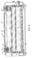
- fuser assembly 76 includes a backup roller 78, a pressure roller 80 and a fuser roller 82. The sheet passes between rollers 80 and 82, the toner images contacting the fuser roller 82 whereby pressure is applied to permanently affix the toner powder images to the copy sheet.
- exiting rollers 84 advance the sheet in the direction of arrow 86 onto catch tray 88 for subsequent removal from the printing machine by the operator.
- Toner particle disturber 90 smears the residual particles adhering to the photoconductive surface thereby facilitating removal thereof by the unit 46.
- Toner particle disturber 90 includes an elastomeric or foam member extending across the width of belt 10. During the first cycle, the elastomeric member is spaced from the photoconductive surface of belt 10. During the second cycle, a motor driven cam moves the elastomeric member into contact with the photoconductive surface so as to smear the residual toner particles prior to the removal thereof from the photoconductive surface.
- a solenoid may be employed to move the elastomeric member of the toner particle disturber 90 into and out of contact with the photoconductive surface of belt 10.
- the photoconductive surface of belt 10 is illuminated by an electroluminescent light strip 92 disposed interiorly of belt 10.
- Electroluminescent strip 92 is positioned between tubular member 50 and toner particle disturber 90. This further reduces the charge attracting residual toner particles to the photoconductive surface of belt 10.
- combined developing-cleaning unit 46 removes the residual toner particles from the photoconductive surface of belt 10.
- voltage source 56 electrically biases tubular member 50 to a potential greater than that of the latent image.
- voltage source 56 electrically biases tubular member 50 to a potential having a magnitude greater than the developing potential of the first cycle.
- the toner particles are attracted to the carrier granules adhering to tubular member 50.
- the residual toner particles are removed from the photoconductive surface and returned to the combined developing-cleaning unit for subsequent reuse.
- a light shutter (not shown) permits light rays from light source 38 to be transmitted through fiber optic tube 44 onto the photoconductive surface. These light rays illuminate the photoconductive surface to remove any residual electrostatic charge remaining thereon prior to the charging thereof for the next successive cycle.
- the shutter prevents light rays from light source 36 from being transmitted through tube 44.
- the fuser assembly 76 as noted comprises the three rolls 78, 80 and 82. These rolls may be fabricated from various materials, for example, steel, stainless steel or aluminum and they are preferably solid rolls.
- the fuser roller 82 contacts the images on the copy sheet as the sheet is moved through a nip 100 formed between the fuser roll 82 and the pressure roller 80.
- the fuser roller 82 is journaled by means of suitable bearings 102 fixedly mounted in end frames 104.
- the pressure roller 80 is also journaled in the end frames 102 by means of sleeve bearings 106 such that its axis is parallel to that of the fuser roll 82.
- the pressure and fuser rollers in a typical configuration have a 26 to 30.5 cm (10.25 to 12 inch) length and the diameter of the pressure roll is smaller than that of the fuser roll so that under load conditions there is conformability between the two rolls.
- the diameter of the pressure roll is preferably on the order of 60 to 88% of the diameter of the fuser roll.
- the backup roller 78 which as can be seen is utilized for biasing the pressure roller 80 into pressure engagement with the fuser roller 82.
- the backup roller 78 with its bearings is carried in movable or floating bearing blocks 110 which are, in turn, supported by the end frames 104.
- a pair of suitably calibrated spring washers 112 are provided for loading the backup roll against the pressure roller 80.
- One surface of the spring engages the top surface of its associated bearing block 110 while the other surface engages the undersurface of a load nut 114. In the loaded condition as viewed in Figures 2 and 3, the spring washers are compressed between the load nut and the bearing block to create the desired force on the backup roller to cause pressure engagement of the fuser and pressure rollers.
- the degree of compression of the springs which determines the force that will be exerted thereby is set by fixing the distance between the bottom of the load nut and the top of the bearing block. This is accomplished by screwing the load nuts into load plates 116 a predetermined amount depending on the force to be exerted, the load plates being fixedly mounted to the fuser frame.
- the rolls are adapted to be loaded and unloaded by means of load screws 118 screwed into bearing blocks 110 which serve to move the bearing blocks in the vertical direction in response to the angular rotation of actuator arms 120 which are attached to the load screws 118 and spaced from the load plates by load washers 122.
- Rotation of the arms 120 from the position shown in Figure 2 acts to raise the bearing blocks which further compresses the spring washers 112 thus removing the load in the nip formed between the pressure and fuser rollers. Accordingly, in the event of a paper jam, the paper can readily be removed from the nip by removing the load in the nip in the foregoing manner.
- the axes of the rollers 80 and 82 are parallel. This is not the case with the backup roller 78.
- the axis of the backup roller is overskewed with respect to the axes of the other two rolls. By overskewed, it is meant that the axis of the backup roller is angulated with respect to the axis of the pressure roller such that the pressure between the backup roller and the pressure roller is peaked at the center and zero at the ends and such that this pressure is distributed over approximately 60% of the length of the pressure roller.
Landscapes
- Physics & Mathematics (AREA)
- General Physics & Mathematics (AREA)
- Fixing For Electrophotography (AREA)
Claims (9)
Applications Claiming Priority (2)
| Application Number | Priority Date | Filing Date | Title |
|---|---|---|---|
| US06/387,061 US4444486A (en) | 1982-06-10 | 1982-06-10 | Three-roll cold pressure fuse for fixing toner images to copy substrates including an overskewed roll |
| US387061 | 1982-06-10 |
Publications (3)
| Publication Number | Publication Date |
|---|---|
| EP0097034A2 EP0097034A2 (de) | 1983-12-28 |
| EP0097034A3 EP0097034A3 (en) | 1984-05-02 |
| EP0097034B1 true EP0097034B1 (de) | 1987-02-25 |
Family
ID=23528294
Family Applications (1)
| Application Number | Title | Priority Date | Filing Date |
|---|---|---|---|
| EP83303350A Expired EP0097034B1 (de) | 1982-06-10 | 1983-06-09 | Druckfixierer |
Country Status (6)
| Country | Link |
|---|---|
| US (1) | US4444486A (de) |
| EP (1) | EP0097034B1 (de) |
| JP (1) | JPS58220167A (de) |
| CA (1) | CA1203838A (de) |
| DE (1) | DE3369891D1 (de) |
| MX (1) | MX152712A (de) |
Families Citing this family (10)
| Publication number | Priority date | Publication date | Assignee | Title |
|---|---|---|---|---|
| JPS6260074A (ja) * | 1985-09-10 | 1987-03-16 | Tokyo Electric Co Ltd | バ−コ−ドスキヤナ− |
| EP0240938B1 (de) * | 1986-04-03 | 1993-01-27 | Fuji Photo Film Co., Ltd. | Bildaufnahmegerät |
| EP0292359B1 (de) * | 1987-05-06 | 1992-09-09 | Fujitsu Limited | Elektrophotographisches Bildaufzeichnungsgerät |
| CA1327831C (en) * | 1988-05-25 | 1994-03-15 | Shigeki Sakakura | Image-forming apparatus |
| US5029310A (en) * | 1989-01-14 | 1991-07-02 | Brother Kogyo Kabushiki Kaisha | Pressure developing device |
| US5296904A (en) * | 1993-03-31 | 1994-03-22 | Xerox Corporation | Three-roll fuser with center pressure roll for black and color application |
| US8913934B2 (en) | 2010-07-07 | 2014-12-16 | Xerox Corporation | Cold pressure transfix in a simplified printer |
| US8265504B2 (en) * | 2010-10-28 | 2012-09-11 | Xerox Corporation | Imaging system with pressure fixing and separate thermal fixing of marking materials on media |
| US8948675B2 (en) * | 2011-05-25 | 2015-02-03 | Xerox Corporation | Image pinning for substrate media handling |
| US8833895B2 (en) * | 2012-05-04 | 2014-09-16 | Xerox Corporation | Transfix roller with adaptive center loading for use in an indirect printer |
Family Cites Families (20)
| Publication number | Priority date | Publication date | Assignee | Title |
|---|---|---|---|---|
| GB1275094A (en) * | 1968-08-22 | 1972-05-24 | Nippon Selfoc Co Ltd | Optical device for transmitting an image |
| US3854975A (en) * | 1971-06-30 | 1974-12-17 | Addressograph Multigraph | Pressure fixing of toners |
| US3874894A (en) * | 1972-10-27 | 1975-04-01 | Addressograph Multigraph | Method and apparatus for ambient temperature pressure fixing of toners |
| JPS5068583U (de) * | 1973-10-22 | 1975-06-18 | ||
| JPS5744350Y2 (de) * | 1973-11-07 | 1982-09-30 | ||
| US3988061A (en) * | 1974-08-01 | 1976-10-26 | Addressograph Multigraph Corporation | Pressure fixing of toners |
| JPS51145324A (en) * | 1975-06-10 | 1976-12-14 | Ricoh Co Ltd | Pressure regulating device for reproduction machine |
| CA1106902A (en) * | 1977-08-05 | 1981-08-11 | Yoshitaka Sasaki | Toner image pressure-fixing device |
| JPS5441144A (en) * | 1977-09-07 | 1979-04-02 | Canon Inc | Fixing device of electrophotography |
| US4192229A (en) * | 1977-10-07 | 1980-03-11 | Canon Kabushiki Kaisha | Fixing apparatus |
| JPS54109851A (en) * | 1978-02-16 | 1979-08-28 | Hitachi Metals Ltd | Pressure fixing apparatus |
| JPS54153940U (de) * | 1978-03-23 | 1979-10-26 | ||
| DK156190C (da) * | 1978-03-31 | 1989-11-27 | Hitachi Metals Ltd | Apparat til trykfiksering af et tonerbillede til et baereark |
| GB2037942A (en) * | 1978-12-04 | 1980-07-16 | Pitney Bowes Inc | A Photocopier Fixing Roller Assembly |
| JPS581774B2 (ja) * | 1978-12-30 | 1983-01-12 | 株式会社リコー | 圧力定着方法及びその装置 |
| JPS5625768A (en) * | 1979-08-09 | 1981-03-12 | Canon Inc | Pressure fixing device |
| DE2943344A1 (de) * | 1979-10-26 | 1981-05-07 | Hoechst Ag, 6000 Frankfurt | Waermedruckfixiervorrichtung |
| JPS56107279A (en) * | 1980-01-31 | 1981-08-26 | Hitachi Metals Ltd | Method for pressure regulation of pressure fixing device |
| JPS56137376A (en) * | 1980-03-31 | 1981-10-27 | Hitachi Metals Ltd | Pressure fixing device |
| US4356764A (en) * | 1981-05-04 | 1982-11-02 | Minnesota Mining And Manufacturing Company | Pressure rollers for toner fusing station |
-
1982
- 1982-06-10 US US06/387,061 patent/US4444486A/en not_active Expired - Fee Related
-
1983
- 1983-05-20 CA CA000428581A patent/CA1203838A/en not_active Expired
- 1983-06-03 JP JP58098179A patent/JPS58220167A/ja active Pending
- 1983-06-08 MX MX197591A patent/MX152712A/es unknown
- 1983-06-09 DE DE8383303350T patent/DE3369891D1/de not_active Expired
- 1983-06-09 EP EP83303350A patent/EP0097034B1/de not_active Expired
Also Published As
| Publication number | Publication date |
|---|---|
| CA1203838A (en) | 1986-04-29 |
| US4444486A (en) | 1984-04-24 |
| EP0097034A2 (de) | 1983-12-28 |
| EP0097034A3 (en) | 1984-05-02 |
| MX152712A (es) | 1985-10-18 |
| JPS58220167A (ja) | 1983-12-21 |
| DE3369891D1 (en) | 1987-04-02 |
Similar Documents
| Publication | Publication Date | Title |
|---|---|---|
| US3591276A (en) | Method and apparatus for offset xerographic reproduction | |
| US3989005A (en) | Oil metering blade device | |
| US6137974A (en) | Photoreceptor belt tensioner system | |
| CA1194919A (en) | Grounding device for moving photoconductor web | |
| JPS6261820B2 (de) | ||
| EP0097034B1 (de) | Druckfixierer | |
| CA1074391A (en) | Fuser sheet guide | |
| GB2206846A (en) | Copy sheet cleaning apparatus | |
| US4335951A (en) | Fusing apparatus | |
| US6160980A (en) | Method and apparatus for reducing contamination of a tackdown, capture or transfer roller on a spliced photoconductor or transport web | |
| US4860047A (en) | Fuser system utilizing a pressure web | |
| US4339194A (en) | Cold pressure fusing apparatus | |
| JPH0514906B2 (de) | ||
| CA1059170A (en) | Fuser roll sheet stripping apparatus | |
| US5613179A (en) | Force applying blade device exhibiting a reduced creep rate | |
| US3901186A (en) | Transfer roller assembly | |
| CA2079609C (en) | Intermediate transfer member | |
| US4105320A (en) | Transfer of conductive particles | |
| EP0164243B1 (de) | Gerät zur Feststellung der Anwesenheit von Tonerteilchen | |
| JP3120071B2 (ja) | 取り外し可能な像形成モジュール | |
| EP1094368B1 (de) | Bandspanngerät | |
| US4014606A (en) | Reproduction machine with textured transfer roller | |
| US5678145A (en) | Xerographic charging and transfer using the pyroelectric effect | |
| CA1036418A (en) | Reproduction machine with textured transfer roller | |
| US4610526A (en) | Reproducing machine |
Legal Events
| Date | Code | Title | Description |
|---|---|---|---|
| PUAI | Public reference made under article 153(3) epc to a published international application that has entered the european phase |
Free format text: ORIGINAL CODE: 0009012 |
|
| AK | Designated contracting states |
Designated state(s): BE CH DE FR GB IT LI |
|
| PUAL | Search report despatched |
Free format text: ORIGINAL CODE: 0009013 |
|
| AK | Designated contracting states |
Designated state(s): BE CH DE FR GB IT LI |
|
| 17P | Request for examination filed |
Effective date: 19840922 |
|
| GRAA | (expected) grant |
Free format text: ORIGINAL CODE: 0009210 |
|
| AK | Designated contracting states |
Kind code of ref document: B1 Designated state(s): BE CH DE FR GB IT LI |
|
| REF | Corresponds to: |
Ref document number: 3369891 Country of ref document: DE Date of ref document: 19870402 |
|
| ET | Fr: translation filed | ||
| ITF | It: translation for a ep patent filed | ||
| PLBE | No opposition filed within time limit |
Free format text: ORIGINAL CODE: 0009261 |
|
| STAA | Information on the status of an ep patent application or granted ep patent |
Free format text: STATUS: NO OPPOSITION FILED WITHIN TIME LIMIT |
|
| 26N | No opposition filed | ||
| ITTA | It: last paid annual fee | ||
| PGFP | Annual fee paid to national office [announced via postgrant information from national office to epo] |
Ref country code: BE Payment date: 19950306 Year of fee payment: 13 |
|
| PGFP | Annual fee paid to national office [announced via postgrant information from national office to epo] |
Ref country code: CH Payment date: 19950428 Year of fee payment: 13 |
|
| PGFP | Annual fee paid to national office [announced via postgrant information from national office to epo] |
Ref country code: GB Payment date: 19950530 Year of fee payment: 13 |
|
| PGFP | Annual fee paid to national office [announced via postgrant information from national office to epo] |
Ref country code: DE Payment date: 19950607 Year of fee payment: 13 |
|
| PGFP | Annual fee paid to national office [announced via postgrant information from national office to epo] |
Ref country code: FR Payment date: 19950609 Year of fee payment: 13 |
|
| PG25 | Lapsed in a contracting state [announced via postgrant information from national office to epo] |
Ref country code: GB Effective date: 19960609 |
|
| PG25 | Lapsed in a contracting state [announced via postgrant information from national office to epo] |
Ref country code: LI Effective date: 19960630 Ref country code: CH Effective date: 19960630 Ref country code: BE Effective date: 19960630 |
|
| BERE | Be: lapsed |
Owner name: XEROX CORP. Effective date: 19960630 |
|
| GBPC | Gb: european patent ceased through non-payment of renewal fee |
Effective date: 19960609 |
|
| REG | Reference to a national code |
Ref country code: CH Ref legal event code: PL |
|
| PG25 | Lapsed in a contracting state [announced via postgrant information from national office to epo] |
Ref country code: FR Effective date: 19970228 |
|
| PG25 | Lapsed in a contracting state [announced via postgrant information from national office to epo] |
Ref country code: DE Effective date: 19970301 |
|
| REG | Reference to a national code |
Ref country code: FR Ref legal event code: ST |