EP0097060A2 - Beatmungsgeräte - Google Patents
Beatmungsgeräte Download PDFInfo
- Publication number
- EP0097060A2 EP0097060A2 EP83303471A EP83303471A EP0097060A2 EP 0097060 A2 EP0097060 A2 EP 0097060A2 EP 83303471 A EP83303471 A EP 83303471A EP 83303471 A EP83303471 A EP 83303471A EP 0097060 A2 EP0097060 A2 EP 0097060A2
- Authority
- EP
- European Patent Office
- Prior art keywords
- valve
- control device
- inlet
- modular
- gas
- Prior art date
- Legal status (The legal status is an assumption and is not a legal conclusion. Google has not performed a legal analysis and makes no representation as to the accuracy of the status listed.)
- Withdrawn
Links
- 230000000241 respiratory effect Effects 0.000 title claims description 4
- 239000007789 gas Substances 0.000 claims abstract description 92
- 210000002345 respiratory system Anatomy 0.000 claims abstract description 9
- 239000001301 oxygen Substances 0.000 claims abstract description 8
- 229910052760 oxygen Inorganic materials 0.000 claims abstract description 8
- 238000002347 injection Methods 0.000 claims abstract description 6
- 239000007924 injection Substances 0.000 claims abstract description 6
- 239000012530 fluid Substances 0.000 claims description 24
- 230000029058 respiratory gaseous exchange Effects 0.000 claims description 12
- 238000011144 upstream manufacturing Methods 0.000 claims description 10
- QVGXLLKOCUKJST-UHFFFAOYSA-N atomic oxygen Chemical compound [O] QVGXLLKOCUKJST-UHFFFAOYSA-N 0.000 claims description 7
- 230000003434 inspiratory effect Effects 0.000 claims description 7
- 238000000034 method Methods 0.000 claims description 6
- 230000001965 increasing effect Effects 0.000 claims description 3
- 150000002926 oxygen Chemical class 0.000 abstract 1
- 235000015097 nutrients Nutrition 0.000 description 13
- 238000010586 diagram Methods 0.000 description 7
- 230000008878 coupling Effects 0.000 description 5
- 238000010168 coupling process Methods 0.000 description 5
- 238000005859 coupling reaction Methods 0.000 description 5
- 210000003300 oropharynx Anatomy 0.000 description 5
- 230000008859 change Effects 0.000 description 4
- 239000000463 material Substances 0.000 description 4
- 238000009423 ventilation Methods 0.000 description 4
- 230000009471 action Effects 0.000 description 3
- 210000004072 lung Anatomy 0.000 description 3
- 210000003800 pharynx Anatomy 0.000 description 3
- CWYNVVGOOAEACU-UHFFFAOYSA-N Fe2+ Chemical compound [Fe+2] CWYNVVGOOAEACU-UHFFFAOYSA-N 0.000 description 2
- 230000008901 benefit Effects 0.000 description 2
- 230000007423 decrease Effects 0.000 description 2
- 230000005611 electricity Effects 0.000 description 2
- 238000002640 oxygen therapy Methods 0.000 description 2
- 230000004044 response Effects 0.000 description 2
- 238000007789 sealing Methods 0.000 description 2
- 210000001584 soft palate Anatomy 0.000 description 2
- 229920000742 Cotton Polymers 0.000 description 1
- 230000000295 complement effect Effects 0.000 description 1
- 150000001875 compounds Chemical class 0.000 description 1
- 230000006835 compression Effects 0.000 description 1
- 238000007906 compression Methods 0.000 description 1
- 125000004122 cyclic group Chemical group 0.000 description 1
- 230000001351 cycling effect Effects 0.000 description 1
- 230000003247 decreasing effect Effects 0.000 description 1
- 230000000994 depressogenic effect Effects 0.000 description 1
- 230000000694 effects Effects 0.000 description 1
- 230000001939 inductive effect Effects 0.000 description 1
- 238000003780 insertion Methods 0.000 description 1
- 230000037431 insertion Effects 0.000 description 1
- 239000000203 mixture Substances 0.000 description 1
- 230000004048 modification Effects 0.000 description 1
- 238000012986 modification Methods 0.000 description 1
- 210000001989 nasopharynx Anatomy 0.000 description 1
- 229920003023 plastic Polymers 0.000 description 1
- 239000004033 plastic Substances 0.000 description 1
- 230000008569 process Effects 0.000 description 1
- 239000000126 substance Substances 0.000 description 1
- 230000009747 swallowing Effects 0.000 description 1
- 238000002560 therapeutic procedure Methods 0.000 description 1
Images




Classifications
-
- A—HUMAN NECESSITIES
- A61—MEDICAL OR VETERINARY SCIENCE; HYGIENE
- A61M—DEVICES FOR INTRODUCING MEDIA INTO, OR ONTO, THE BODY; DEVICES FOR TRANSDUCING BODY MEDIA OR FOR TAKING MEDIA FROM THE BODY; DEVICES FOR PRODUCING OR ENDING SLEEP OR STUPOR
- A61M16/00—Devices for influencing the respiratory system of patients by gas treatment, e.g. ventilators; Tracheal tubes
- A61M16/20—Valves specially adapted to medical respiratory devices
-
- A—HUMAN NECESSITIES
- A61—MEDICAL OR VETERINARY SCIENCE; HYGIENE
- A61M—DEVICES FOR INTRODUCING MEDIA INTO, OR ONTO, THE BODY; DEVICES FOR TRANSDUCING BODY MEDIA OR FOR TAKING MEDIA FROM THE BODY; DEVICES FOR PRODUCING OR ENDING SLEEP OR STUPOR
- A61M16/00—Devices for influencing the respiratory system of patients by gas treatment, e.g. ventilators; Tracheal tubes
- A61M16/021—Devices for influencing the respiratory system of patients by gas treatment, e.g. ventilators; Tracheal tubes operated by electrical means
-
- A—HUMAN NECESSITIES
- A61—MEDICAL OR VETERINARY SCIENCE; HYGIENE
- A61M—DEVICES FOR INTRODUCING MEDIA INTO, OR ONTO, THE BODY; DEVICES FOR TRANSDUCING BODY MEDIA OR FOR TAKING MEDIA FROM THE BODY; DEVICES FOR PRODUCING OR ENDING SLEEP OR STUPOR
- A61M16/00—Devices for influencing the respiratory system of patients by gas treatment, e.g. ventilators; Tracheal tubes
- A61M16/20—Valves specially adapted to medical respiratory devices
- A61M16/201—Controlled valves
-
- A—HUMAN NECESSITIES
- A61—MEDICAL OR VETERINARY SCIENCE; HYGIENE
- A61M—DEVICES FOR INTRODUCING MEDIA INTO, OR ONTO, THE BODY; DEVICES FOR TRANSDUCING BODY MEDIA OR FOR TAKING MEDIA FROM THE BODY; DEVICES FOR PRODUCING OR ENDING SLEEP OR STUPOR
- A61M16/00—Devices for influencing the respiratory system of patients by gas treatment, e.g. ventilators; Tracheal tubes
- A61M16/20—Valves specially adapted to medical respiratory devices
- A61M16/208—Non-controlled one-way valves, e.g. exhalation, check, pop-off non-rebreathing valves
- A61M16/209—Relief valves
-
- A—HUMAN NECESSITIES
- A61—MEDICAL OR VETERINARY SCIENCE; HYGIENE
- A61M—DEVICES FOR INTRODUCING MEDIA INTO, OR ONTO, THE BODY; DEVICES FOR TRANSDUCING BODY MEDIA OR FOR TAKING MEDIA FROM THE BODY; DEVICES FOR PRODUCING OR ENDING SLEEP OR STUPOR
- A61M16/00—Devices for influencing the respiratory system of patients by gas treatment, e.g. ventilators; Tracheal tubes
- A61M16/20—Valves specially adapted to medical respiratory devices
- A61M16/201—Controlled valves
- A61M16/202—Controlled valves electrically actuated
-
- A—HUMAN NECESSITIES
- A61—MEDICAL OR VETERINARY SCIENCE; HYGIENE
- A61M—DEVICES FOR INTRODUCING MEDIA INTO, OR ONTO, THE BODY; DEVICES FOR TRANSDUCING BODY MEDIA OR FOR TAKING MEDIA FROM THE BODY; DEVICES FOR PRODUCING OR ENDING SLEEP OR STUPOR
- A61M16/00—Devices for influencing the respiratory system of patients by gas treatment, e.g. ventilators; Tracheal tubes
- A61M16/20—Valves specially adapted to medical respiratory devices
- A61M16/208—Non-controlled one-way valves, e.g. exhalation, check, pop-off non-rebreathing valves
-
- A—HUMAN NECESSITIES
- A61—MEDICAL OR VETERINARY SCIENCE; HYGIENE
- A61M—DEVICES FOR INTRODUCING MEDIA INTO, OR ONTO, THE BODY; DEVICES FOR TRANSDUCING BODY MEDIA OR FOR TAKING MEDIA FROM THE BODY; DEVICES FOR PRODUCING OR ENDING SLEEP OR STUPOR
- A61M2205/00—General characteristics of the apparatus
- A61M2205/84—General characteristics of the apparatus for treating several patients simultaneously
Definitions
- This invention relates to respiratory apparatus, in particular resuscitation apparatus.
- Resuscitation apparatus is used to resuscitate a person whose respiration has become insufficient to maintain life for any substantial period of time.
- the resuscitation apparatus used depends on the particular patient (in particular his or her size) and the circumstances in which the patient is found. A large number of different types of resuscitation apparatus have thus been developed to meet the various different situations that arise in practice. However, known resuscitation apparatus tend to be of limited utility.
- resuscitation apparatus comprising an inlet connectible to a source of respirable gas, an outlet connectible to a patient's respiratory system, duct means interconnecting said inlet and said outlet, a valve interposed in said duct means and operable selectively manually and automatically, manually operable means connected to said valve and operable manually to operate said valve, and automatically operable means connected to said valve and operable automatically to operate said valve.
- resuscitation apparatus comprising a housing; an inlet port in a wall of the housing connectible to a source of respirable gas; an outlet port in a wall of the housing connectible to means for administering respirable gas to a patient; a flow pasasge extending within the housing from the inlet port to the outlet port; a valve in said passage, the valve being capable of being operated manually or automatically; means operable manually from outside of the housing for opening and closing the valve; and a connector in the wall of the housing associated with the valve and suitable for connecting the valve to external means for operating the valve automatically.
- the resuscitation apparatus is thus capable of being operated manually or automatically to supply pulses of respirable gas to a patient.
- the connector may be electrical and the valve have a solenoid actuator so that electronic control means may be employed to operate the valve.
- electronic control means may be employed to operate the valve.
- an electronic control device for operating the valve automatically this device having an electrical connector engageable with the electrical connector of the apparatus.
- the control device may have its own power supply or may be connectible to a mains electricity supply.
- the control device preferably has a housing containing suitable electronic control circuits and a power supply if it is not to be operated from a mains electricity supply.
- the control circuits are adapted to generate electrical signals which effect opening and closing of the valve, preferably at a variable frequency.
- Each period for which the valve is open corresponds to the inspiratory phase of a patient's breathing, and each period for which the valve is closed corresponds to the expiratory phase of a patient's breathing.
- the control device is preferably adapted to give a constant inspiratory phase/expiratory phase ratio, i.e. the ratio of the duration of each pulse of gas to the interval between consecutive pulses is a constant.
- the ratio is 1:2.
- each pulse of gas can be varied by manual setting of a suitable control.
- a suitable control This makes it possible for the resuscitation apparatus to supply pulses of respirable gas that can be adjusted to suit the size (or lung capacity) of the patient be he or she a newly born baby or a fully grown adult with a relatively large lung capacity.
- the range of settings of the manual control may vary the frequency of the gas pulses from 10 or 15 to 40 per minute.
- the resuscitation apparatus may be set to operate automatically to produce gas pulses at a chosen frequency by using the control device. It is, however, a feature of the resuscitation apparatus that it can be operated entirely manually and without connecting a control device thereto. This can be done by operating the said manually operable means for opening and closing the valve (which means is conveniently a push-button). Manual operation of the valve offers flexibility in that it is possible to produce any desired pattern of gas pulses.
- the resuscitation apparatus is thus usable even if there is no available power supply or automatic means for operating the valve or if the condition of the patient is so serious that there is no time to connect the resuscitation apparatus to any available means for operating the valve automatically.
- the valve is preferably of a kind such that when operating automatically, the control signals it recieves are able to be manually over-ridden.
- Such means may comprise an artificial airway.
- a preferred artificial airway is as claimed and described in UK Patent Specification No. 1 558 171.
- Such an artificial airway is anatomically-shaped and has a flange at one end to limit its insertion into a patient's airway and a fixed injector at the flanged end for injecting respirable gas at relatively high flow rates into the airway to entrain air from the atmosphere.
- the length of the airway is related to the size of the patient so that the inner end of the airway, when the airway is in position, lies in the oral pharynx.
- the outlet port may be connected to a conventional non-return valve which is fitted with a suitable taper (or face mask).
- the non-return valve may be suitable for a child and fitted with a British Standard paediatric taper or maybe suitable for an adult and fitted with the British Standard adult taper. In both instances, there may be a flow control valve in the conduit connecting the outlet port to the non-return valve.
- Other alternative means for delivering respirable gas to the patient that are connectible to the outlet port include endotracheal and trachaeostomy tubes.
- the resuscitation apparatus preferably has in a wall of the housing a second outlet port communicating with the flow passage in the housing upstream of the valve.
- the second outlet port may be used to supply respirable gas continuously to a second patient while resuscitating a first.
- the second outlet port may be connected to a manually operable valve, downstream thereof, to produce a second pulsed supply of respirable gas.
- a method of assembling a resuscitation apparatus comprising selecting a control device from a range of modular control devices, connecting said control device to a respirable gas flow control valve to be operated by said control device, selecting a respirable gas administering device from a range of modular respirable gas administering devices, and connecting said administering device to downstream of said valve for administering said gas to a patient's respiration system.
- a collection of modular devices from a selection from which a resuscitation apparatus can be assembled comprising a respirable gas flow valve, a range of modular control devices each connectible to said valve for opening the same, and a range of modular respirable gas administering devices connectible to downstream of said valve for administering said gas to a patient's respiratory system.
- a resuscitation apparatus comprising a respirable gas flow valve, a modular control device connected to said valve for operating the same, and a modular respirable gas administering device connected to downstream of said valve for administering said gas to a patient's respiratory system.
- resuscitation apparatus comprising an inlet connectible to a source of respirable gas, an outlet connectible to a patient's respiratory system, duct means interconnecting said inlet and said outlet, a valve interposed in said duct means and operable automatically, and electrical means connected to said valve and arranged to operate said valve automatically, said electrical means including electrical switching means arranged to detect the presence or absence of said gas under pressure upstream of said valve and accordingly to energize or de-energize said electrical means.
- a respiratory apparatus including first and second variable flow control valves which serve to control respective flows of gaseous fluid therethrough, and a non-pneumatic adjusting linkage interconnecting the valves so that adjustment of the first valve is accompanied by adjustment of the second valve.
- a valve device comprising an inlet for fluid, an outlet for said fluid, valve closure means arranged to control flow of said fluid from said inlet to said outlet, and a pilot pressure chamber bounded by said valve closure means, the effective area of said valve closure means exposed to the pressure of said fluid between said inlet and said outlet being less than the effective area of said valve closure means exposed to the pressure in said chamber.
- a valve device comprising a valve housing, a valve closure member movable in said housing from an open position to a closed position, an inlet to said housing for fluid, and an outlet from said housing for fluid, the arrangement being such that, as said member moves from said open position to said closed position, initially fluid can flow via a first path from said inlet to a limited degree and via a second path from said inlet to no more than a limited extent, but subsequently said member enables flow of said fluid via said second path from said inlet to greater than said limited extent, whereby said fluid can flow from said inlet to an increased extent.
- a valve device comprising a valve housing, a valve closure member movable in said housing from an open position to a closed position, a tubular inlet to said housing for fluid, and an outlet from said housing for fluid, said member being in the form of a bobbin closely encircling said tubular inlet and including first and second flanges of substantially equal external dimension transverse to the bobbin axis.
- a valve device comprising a first valve including a first valve closure member arranged to open automatically upon occurrence of a predetermined pressure differential thereacross, a second valve which includes a selectively closable second valve closure member and through which the first valve exhausts when the second valve closure member is open, and a third valve which includes a third valve closure member arranged to open automatically upon occurrence of a predetermined pressure differential thereacross and through which the first valve exhausts when the second valve closure member is closed, the arrangement being such that pressure upstream of said first valve at which said third valve opens is higher than that pressure upstream of said first valve at which said first valve opens.
- a resuscitation apparatus 2 includes a box-shaped housing 4.
- the longer opposed side walls of the box-shaped housing 4 are indicated by the reference numerals 6 and 8, and the shorter side walls by the reference numerals 10 and 12. (The side 10 is also shown in Figure 3).
- the top and bottom walls of the box or housing 4 are indicated by the reference numerals 14 and 16 respectively. (The bottom 16 is also shown in Figure 4).
- the housing 4 is conveniently formed of any suitable durable plastics material.
- the inlet port 18 is adapted to be connected to a source of respirable gas at high pressure (e.g. an oxygen cylinder fitted with a regulator).
- a source of respirable gas at high pressure e.g. an oxygen cylinder fitted with a regulator.
- 'high pressure' is meant a pressure higher than normal respirable pressures.
- the outlet ports 20 and 22 may comprise self-capping connectors of the Schraeder type or any other simple connecting device.
- the housing 4 contains a solenoid (on-off) valve (not shown in Figure 1) which is alternatively operable by a push-button 24 projecting through the top wall 14.
- the valve is shown schematically in Figure 5 and is indicated by the reference 26. It is located in a main flow passage 28 connecting the inlet port 18 to the first outlet port 20. A tributary 30 from the main flow passage 28 extends from upstream of the valve 26 to the second outlet port 22.
- the valve 26 is capable of being operated manually by the push-button 24 or automatically by the solenoid 32. If the valve is operating automatically the push-button 24 may be operated to override the solenoid 32. In order to keep down the total size of the resuscitation apparatus 2, it is desirable that the valve 26 be relatively small.
- the valve may, for example, be a Martonair (trade mark) valve having two valve positions and three ports (with one of the outlet ports blocked).
- the solenoid 32 of the valve 26 is electrically connected to an electrical socket 34 in the bottom wall 16 of the housing 4. This socket is adapted to be mated with the complementary plug 38 of an electronic valve control box or device 36 (see Figure 2).
- the control box 36 typically has a switch 40 for switching on its own internal power supply (not shown) which may typically comprise rechargeable or disposable batteries.
- the control box 36 also has a control knob 42 for adjusting the frequency with which the valve 26 may be opened and closed.
- the control knob 42 is associated with electronic circuits capable of generating signals effective to open and close the valve 26 so as to supply to the outlet port 20 pulses of gas as shown in Figure 6.
- each pulse corresponds to the inspiratory phase of a patient's breathing and the interval between one pulse and the next to the expiratory phase of the patient's breathing. Accordingly, a constant inspiratory phase/expiratory phase ratio of 1:2 is given by operating the valve automatically using the control box. Moreover, by adjusting the control knob 42 the duration of each pulse may be adjusted to suit the particular patient without altering the inspiratory phase/expiratory phase ratio.
- Electronic control circuits capable of generating the necessary signals for such operation of the valve 26 are well known and will not be described in detail in this specification. Suffice it to state that typically, two integrated circuits are required, one for generating rapid electrical pulses, the other containing a gate means for selecting pulses. Typically, the control device may produce from 15 to 40 gas pulses per minute.
- valve 26 may be operated manually by means of the push-button 28 to produce a pulsed gas supply such as that shown in Figure 6.
- the first outlet port 20 may be connected to any suitable means for delivering the pulsed high pressure gas supply to the patient.
- the preferred means is an anatomically-shaped artificial airway as claimed and described in UK Patent Specification 1 558 171. Such an airway is shown in Figure 7 and 8. Connecting the airway shown in Figures 7 and 8 to the outlet port 20 of the apparatus shown in Figures 1 and 3 to 5 forms a complete manually-operable resuscitator. If the control box shown in Figure 2 is connected to the apparatus shown in Figures 1 and 3 to 5, the resuscitator may operate automatically.
- the airway shown in Figures 7 and 8 consists basically of an open-ended tube 52 having at one end 60 an outwardly-directed flange 54.
- the tube 52 is intended to be fitted into a patient's mouth so that the tube overlies the patient's tongue and extends into the oro-pharynx.
- the flange 54 is intended to come into contact with either the patient's teeth or lips so as to prevent the patient from swallowing the airway and to limit the extent to which the airway projects into the patient's oro-pharynx.
- Extending to the side of the flange 54 is a length of tubing 56 which is able to be connected to the outlet port 20 of the resuscitation apparatus 2.
- the end of the tubing which is remote from the outlet port 20 terminates in a nozzle (or primary injector) 58 which is shaped so as to inject a jet of gas at high-pressure into the interior of the tube 54.
- the nozzle 58 may be of one piece with the tubing 56.
- the tubing 56 and nozzle 58 may be of one piece with the flange 54 and therefore with the tube 52.
- the tubing 56 may be bonded or otherwise secured in a non-detachable manner to the flange 54.
- the interior of the tube 52 is open to the atmosphere through the central opening 60 in the flange 54.
- the pulses of respirable gas issue as jets from the nozzle (or primary injector) 58 and entrain air from the atmosphere.
- Each jet of gas and the entrained air are typically mixed completely by the time the mixture reaches the distal end of the airway in the patient's oro-pharynx.
- the oro-pharynx flares out like the throat of a venturi.
- the end of the airway in the throat constituted a secondary injector entraining additional air through the nose and around the airway in the mouth.
- There is only a relatively weak suction but the important result is that it is not necessary to pinch the nose or cover the mouth to ensure inflation.
- the existence of a low suction pressure in these zones can be demonstrated by the movement of a wisp of cotton wool.
- the outlet port 20 of the resuscitation apparatus illustrated in Figures 1 and 3 to 5 may be connected to alternative devices for delivering pulses of respirable gas to the patient.
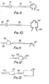
- FIG. 9 Examples of suitable alternative equipment are shown in Figures 9 and 10.
- the equipment shown in Figure 9 comprises a flow control valve 70, a non-return valve 72 suitable for an infant or child, and a face mask 74 suitable for an infant or child.
- the equipment shown in Figure 10 is analogous to that shown in Figure 9 but is adapted for resuscitation of an adult.
- the equipment comprises a flow control valve 80, a non-return valve 82 suitable for an adult, and a face mask 84 suitable for an adult.
- the continuous supply of respirable gas to the outlet port 22 of the resuscitation apparatus shown in Figure 1 may be emloyed in one of three alternative ways.
- a continuous flow of respirable gas may be supplied to assist the breathing of a patient who does not require resuscitation.
- a pulsed flow of respirable gas may be created from the continuous flow and supplied to resuscitate a second patient.
- a flow of gas may be supplied to an inflatable pillow so as to inflate it to a desired degree. The pillow may then be used to prop the head of a patient. Suitable equipment for these purposes is illustrated schematically in Figures 11, 12 and 13.
- the equipment shown in Figure 11 comprises a flow control valve 90, an oxygen mask 92 and suitable lengths of flexible connecting tubing 96.
- the equipment shown in Figure 12 comprises a manually (e.g. push-button) operable on-off valve 102 whose inlet is connected to a suitable length of flexible tubing 104.
- the outlet of the valve is connectible with the artificial airway shown in Figures 7 and 8 or with the equipment shown in Figure 9 or 10.
- the valve 102 may thus be operated manually to resuscitate one patient while another patient is resuscitated by means of pulses of respirable gas leaving the port 20 of the apparatus shown in Figure 1.
- Such pulses can be supplied automatically by means of the control box shown in Figure 2.
- one suitably qualified person can use the apparatus shown in Figure I to resuscitate two patients simultaneously.
- the apparatus shown in Figure 13 comprises a manually operable (e.g. push-button) valve 110, an inflatable pillow 112 of suitable material and suitable lengths of flexible connecting tubing 114.
- the valve 110 may be kept open until the pillow 112 has been inflated to a suitable degree and then closed.
- the tubing employed in the airway shown in Figures 7 and 8 and the tubing employed in the equipment shown in Figures 9 to 13 may be provided at the end to be connected to the port 20 or 22 of the apparatus shown in Figure 1 with suitable connectors (not shown).
- the ports 20 and 22 have connectors of different sizes from one another so that equipment intended to be connected to the port 20 cannot be connected to the port 22, and vice versa.
- the equipment shown in Figures 11 to 13 may be kept or stored with the resuscitation apparatus shown in Figures 1 and 3 to 5, the control box shown in Figure 2 and suitable airways of the kind shown in Figures 7 and 8 (or equipment of the kind shown in Figures 9 and 10) to provide a resuscitation kit which may be used to resuscitate patients ranging from neonates to fully grown adults in a number of different situations.
- hospitals, rescue services and ambulance services may select only those parts of the whole range of apparatus and equipment illustrated in the drawings so as to meet their own particular requirements.
- a purchaser would buy the connector; the reducing valve; at least one of the valve control devices “PB”, “UO” and “AC”; the coupling; and at least one of the respirable gas administering devices "IA”, “IUO”, “PVA”, “PVA/NIV”, “PVA/NIV/WW”, and “BV". In practice, he would purchase a considerable part of the ranges available.
- the connector, the reducing valve, a valve control device, the coupling, and an administering device would be assembled together, the valve control device and the administering device being selected according to the circumstances and the type of patient.
- This method of assembling of the apparatus enables one apparatus with additional interchangeable modules to cope with a wide variety of patients in a wide variety of circumstances.
- the apparatus is especially advantageous for the apparatus to be so designed that the first few breaths can be at a high flow rate, in order to expand the lungs properly, but the following breaths at a low flow rate more corresponding to normal breathing.
- the manual control device PB is advantageously designed to open the reducing valve sufficiently to give a high rate of flow
- the automatic valve control devices AC are advantageously designed to give a low rate of flow from the valve.
- Figures 15 to 17 show possible designs of the device ACb electronic or ACe electronic.
- the device naturally requires a power source 100.
- This power source can be any supply of electrical energy, for example dry cells, rechargeable batteries or the mains.
- the power source 100 is connected to an oscillator 101, a ratio divider 102 and a solenoid-operated valve 103.
- the oscillator is a variable frequency oscillator and can be any circuit capable of producing a digital train of pulses, which may be varied in frequency by the setting of a control 104.
- the ratio divider 102 can be any circuit which may be programmed to operate the solenoid-operated valve 103 for 1 out of n of the incoming pulses from the oscillator 101.
- the process is cyclic and repeats every n pulses.
- the valve 103 comprises an elctro-mechanical actuator assembly which when energised allows a change in the state of flow of the gas to be controlled.
- the oscillator is a fixed frequency oscillator with a fixed control 106.
- the output from the oscillator 105 is fed to a frequency divider 107 also connected to the power source 100.
- a selector 108 is used to select a desired frequency signal from the divider 107 and feed it to the ratio divider 102.
- the frequency divider 107 is a circuit which can take the incoming pulse train from the oscillator 105 and produce a series of frequency divided outputs.
- the circuit may be extended to allow for modification of the output wave form of the ratio divider 102 in response to a stimulus from an outside source.
- a control signal from the ratio divider 102 is fed to a trigger device 109.
- the trigger device 109 emits an electrical response signal to modify the output from the ratio divider 102.
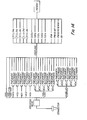
- FIG. 18 A gas bottle 110 is shown connected via a bottle valve 111 to a cycling unit 112. Also arranged downstream of the valve 111 is a slide valve 113 and, downstream thereof, a piston-in- cylinder device 114 arranged to control a pair of electrical contacts 115 arranged in the power supply circuit of the electronic control device.
- the piston 116 of the device 114 has been pressed by a return spring 117 into a position corresponding to an open position of the contacts 115, the gas in the cylinder having been expelled via an exhaust port 118 of the valve 113.
- the downstream gas pressure of the valve 111 increases and is applied to the left-hand end of the slide valve 113 to press it against the action of a return spring 119 into a position in which a through passage 120 of the valve 113 communicates the gas pressure downstream of the valve 111 to the device 114, so forcing the piston 116 against the action of the spring 117 to close the contacts 115.
- the pressure downstream of the valve 111 falls and the spring 119 returns the valve 113 into its exhaust condition shown.
- the pneumatic circuit part shown therein includes three conduits 202, 203 and 204 which are supplied from the nutrient gas supply 201.
- the conduit 202 divides into two conduits 205 and 206, of which the conduit 205 leads to the inlet of a normally-open, pilot-controlled valve 207, and the conduit 206 to a normally-closed, pilot-controlled valve 208.
- the nutrient gas passes straight through the valve 207 and through a non-return valve 209 to a pilot pressure chamber of the valve 208, so enabling nutrient gas to flow through the valve 208 from the conduit 206 to a conduit 210 which leads via an adjustable flow restrictor 211 to a patient valve, which is shown in Figure 21.
- Nutrient gas in the conduit 210 can flow via a conduit 212 containing a non-return valve 213 to a pilot pressure chamber of the valve 207.
- Nutrient gas is trapped in the pilot conduits by the non-return valves 209 and 213 and fills reservoirs 214 and 215 connected upstream of the non-return valves 209 and 213, respectively.
- the reservoirs 214 and 215 can empty only through respective adjustable bleeds 216 and 217.
- the adjustable bleeds 216 and 217 and the adjustable flow restrictor 211 are linked by some non-pneumatic means such that their throughflow cross-sections remain in a fixed ratio relative to one another.
- An example of such non-pneumatic means is shown diagrammatically in Figure 20, in which inter-meshing gear wheels 218, 219 and 220 are connected to adjusting shafts of the restrictor 211 and the bleeds 216 and 217, respectively.
- Inserted in the conduit 203 is a manually adjustable flow restrictor 221.
- the conduits 203 and 210 downstream of the restrictors 221 and 211, respectively, may remain independent of each other, or may be joined together to give higher flow rates.
- the conduit 204 which contains a manually adjustable flow restrictor 222, can give a continuous flow of nutrient gas to the patient.
- the outlets from the flow restrictors 211, 221 and 222 are preferably in the form of quick-release couplings to allow easy change from one mode of treatment to another. These three outlets may all be used simultaneously on three respective patients, or two of these outlets may be used on two respective patients, or one outlet on a single patient.
- the restrictor 221 may be arranged to be non-pneumatically linked for adjustment with the restrictor 211, such linkage being instead of or as a selectable alternative to manual adjustment of the restrictor 221.
- linkage may be achieved by means of connecting to the gear wheel 211 by way of an intermediate gear wheel 223, a gear wheel 224 connected to an adjusting shaft of the restrictor 221.
- the apparatus described with reference to Figures 19 and 20 has an advantage of being a single apparatus usable for oxygen therapy (or therapy utilizing another gaseous substance), manual intermittent positive pressure ventilation, or automatic intermittent positive pressure ventilation, and enabling up to three patients to be treated at the same time. For example, in midwifery, the baby may need manual or automatic intermittent positive pressure ventilation, while the mother has oxygen therapy.
- the pneumatic circuit shown in Figure 19 comprises two variable bleeds 216 and 217 and two fixed-volume reservoirs 214 and 215, it could instead comprise two fixed-flow-rate bleeds and two variable-volume reservoirs. Alternatively, it could have two variable bleeds giving coarse control of the flow rates and two variable reservoirs giving fine control of the flow rates.
- the reservoir 214 and the bleed 216 determine the inhalation time period, whilst the reservoir 215 and the bleed 217 determine the exhalation time period.
- the ratio of the inhalation time period to the exhalation time period is advantageously about 1:2. Owing to the non-pneumatic linkage between the restrictor 211 and the bleeds 216 and 217, not only is it possible to ensure that this ratio remains constant, but also the respiration frequency varies automatically with adjustment of the flow rate to the patient, so that the apparatus is usable with simple adjustment for either a large adult or a small child. In practice, with a decrease in the flow rate to the patient, there is an increase in the ventilation frequency, and vice-versa.
- the patient valve shown in Figure 21 comprises a bobbin 230 which slides with clearance in a shell 231 which has an inlet 232 for nutrient gas and an outlet 233 for exhaled gas.
- the shell 231 also comprises an opening 234 leading to the patient and an opening 235 receiving a screw-in positive pressure relief valve 236.
- the nutrient gas entering the inlet 232 flows along an inlet tube 237 encircled by the bobbin 230.
- the pressure of the gas urges the bobbin 230 against the action of a return spring 238 into a position in which it seals the outlet 233.
- the pressure of the nutrient gas in the bobbin 230 is the inlet pressure of that gas, until a hole 239 through the tube 237 is exposed by the movement of the bobbin 230 towards its position sealing the outlet 233, whereupon the pressure in the bobbin 230 drops, but at the same time the pressure against the inside face of the closure plate 240 of the bobbin 230 rises, and this constitutes a substantial part of the sealing force, especially at low flow rates. Exposure of the hole 239 allows high flow rates of nutrient gas to be transmitted to the patient.
- the two flanges of the bobbin are of equal external diameter to each other.
- the valve 236 is a screw-in unit which can be exchanged for another simple valve or a compound valve device such as that illustrated in Figure 22, which is for neonates.
- the valve device includes a threaded inlet stem 250 which is screwed into the opening 235.
- the device also includes a primary valve 251 which opens at comparatively low pressure in the stem 250, for example 30 cm. H 2 0.
- the gas from the valve 251 exhausts through a port 252 of another valve 253 and thence through openings 254 to atmosphere.
- the valve 253 is normally kept open by its spring 255. However, when a knob 256 of the valve 253 is depressed, the port 252 is sealed and the gas is then voided through a port 257 of a valve 258 and thence through openings 259 to atmosphere.
- the closure member of the valve 258 is urged to close the port 257 by its spring 260, which is set to give an opening pressure for the valve 258 corresponding to a comparatively high pressure in the stem 250, for example 55 cm. H 2 0.
- the normally-open, pilot-controlled valve 207 is seen in more detail in Figure 23. It comprises a valve housing 270 with a nutrient gas inlet 271 and a nutrient gas outlet 272 connected in the conduit 205.
- the housing 270 has a hollow interior 273 to and from which lead the inlet 271 and the outlet 272, the interior 273 containing co-axially a valve closure member 274 in the shape of a pin with a cylindrical head and a conical tip.
- a seal 275 around the head of the member 274 and an annular seal 276 encircling the shank of the member 274 divide the interior 273 into a pilot pressure chamber 277, an atmospheric pressure chamber 278, and a nutrient gas line pressure chamber 279.
- the chamber 277 communicates via a connection 280 with the conduit 212, the chamber 278 with atmosphere through an aperture 281, and the chamber 279 with the inlet 271 and the outlet 272.
- the housing 270 Near the end of the chamber 279 further from the chamber 277 the housing 270 carries co-axially an annular seal 282 which is of considerably smaller diameter than is the seal 276.
- An annular compression spring 283 encircling the shank of the member 274 and acting between the housing 270 and the head of the member 274 urges the member 274 into a fully open position.
- the line pressure in the chamber 279 is applied over the relatively small effective area of the member 274 at its tip, whilst the pilot pressure in the chamber 277 is applied over the relatively large effective surface area of the member 274 at its head.
- the valve member 274 is kept open by the spring 283 which is relatively weak.
- the conical shape of its tip gives a decreasing surface area exposed to the full line pressure, so giving a rapid change of state from the open condition to the closed condition.
- the line pressure is applied over only the relatively very small effective area defined by the seal 282.
- the shape of the tip gives an increasing area exposed to the full line pressure, so giving a rapid change of stage from the closed condition to the open condition.
- the pilot-controlled normally-closed vlave 208 shown in Figure 24 is identical to the valve 207, except that the aperture 280' leads to atmosphere, so that the chamber 277' is the atmospheric chamber; the aperture 281' is connected to the conduit 212, so that the chamber 273' becomes the pilot pressure chamber; and the spring 283' is situated in the chamber 277' and so urges the member 274 into its fully closed condition.
- the seal 282 defines the relatively very small surface area over which the line pressure acts on the member 274.
- the relatively large area now exposed to the line pressure and defined by the seal 276 compensates for any drop in the line pressure.
- the pilot pressure in the chamber 273' still acts over a yet larger area, so that the valve responds to a relatively low pilot pressure.
- an inductive coil 284 can encircle the housing 270, which would be made of non-ferrous material, whilst the member 274 would be made of ferrous material.
- Such valve device may be used with either pneumatic or electrical pulsing, whereby it is possible to have an electrical override of the pneumatic circuit, or pneumatic override of the electrical circuit.
- the member 274 By providing a longer shank of the member 274, the member can be used to open and close further control inlets and outlets, thereby providing a three-, four-or more- port valve according to need, but keeping the principle of an inlet pilot.
- the bobbin 230 has its two flanges of virtually equal external diameter, so that the ratio of the exposed areas of the flanges is not a significant factor in the motion of the bobbin.
Landscapes
- Health & Medical Sciences (AREA)
- Pulmonology (AREA)
- Heart & Thoracic Surgery (AREA)
- Engineering & Computer Science (AREA)
- Anesthesiology (AREA)
- Biomedical Technology (AREA)
- Emergency Medicine (AREA)
- Hematology (AREA)
- Life Sciences & Earth Sciences (AREA)
- Animal Behavior & Ethology (AREA)
- General Health & Medical Sciences (AREA)
- Public Health (AREA)
- Veterinary Medicine (AREA)
- Pharmaceuticals Containing Other Organic And Inorganic Compounds (AREA)
- Percussion Or Vibration Massage (AREA)
Applications Claiming Priority (2)
| Application Number | Priority Date | Filing Date | Title |
|---|---|---|---|
| GB8217354 | 1982-06-15 | ||
| GB8217354 | 1982-06-15 |
Publications (2)
| Publication Number | Publication Date |
|---|---|
| EP0097060A2 true EP0097060A2 (de) | 1983-12-28 |
| EP0097060A3 EP0097060A3 (de) | 1984-08-15 |
Family
ID=10531059
Family Applications (1)
| Application Number | Title | Priority Date | Filing Date |
|---|---|---|---|
| EP83303471A Withdrawn EP0097060A3 (de) | 1982-06-15 | 1983-06-15 | Beatmungsgeräte |
Country Status (2)
| Country | Link |
|---|---|
| EP (1) | EP0097060A3 (de) |
| JP (1) | JPS5940867A (de) |
Cited By (11)
| Publication number | Priority date | Publication date | Assignee | Title |
|---|---|---|---|---|
| GB2164572A (en) * | 1984-09-22 | 1986-03-26 | Draegerwerk Ag | A respiration device |
| GB2282542A (en) * | 1993-10-06 | 1995-04-12 | Instruments & Movements Ltd | Ventilator for promoting lung function |
| EP0835671A1 (de) * | 1996-10-11 | 1998-04-15 | Georges Boussignac | Gerät zur Unterstützung der Atmung |
| EP0850083A4 (de) * | 1995-08-17 | 2002-05-29 | Univ Florida | Per mikroprozessor hybridgesteuerte beatmungseinheit |
| WO2003070308A1 (en) * | 2002-02-20 | 2003-08-28 | Xenogen Corporation | Multiple output anesthesia system |
| WO2005079898A3 (de) * | 2004-02-20 | 2005-11-03 | Weinmann G Geraete Med | Modulare vorrichtung zur befeuchtung von atemgas |
| US8901516B2 (en) | 2010-09-01 | 2014-12-02 | Spectral Instruments Imaging, LLC | Excitation light source assembly |
| US9347894B2 (en) | 2010-09-01 | 2016-05-24 | Spectral Instruments Imaging, LLC | Methods and systems for producing visible light and x-ray image data |
| CN109646782A (zh) * | 2018-12-29 | 2019-04-19 | 惠州市美亚飞电器有限公司 | 一种手动脉冲供氧装置及其供氧方法 |
| WO2021198544A1 (es) * | 2020-03-29 | 2021-10-07 | Proton New Energy Future, S.L. | Módulo de distribución inteligente para respiradores |
| EP4397345A4 (de) * | 2021-08-30 | 2025-08-06 | Tarazona Javier Montejo | Autonomes notfallsystem und verfahren zur verwendung bei atemstillstand für kardiopulmonale reanimation mit einer beatmungsmaske mit co2-sensor, selbstregulierender sauerstoffquelle und zervikaler unterstützung |
Families Citing this family (1)
| Publication number | Priority date | Publication date | Assignee | Title |
|---|---|---|---|---|
| JP7352964B2 (ja) * | 2020-04-13 | 2023-09-29 | 日本気圧バルク工業株式会社 | 人工呼吸器システム |
Family Cites Families (4)
| Publication number | Priority date | Publication date | Assignee | Title |
|---|---|---|---|---|
| FR1257143A (fr) * | 1960-02-17 | 1961-03-31 | Regulation Automatique | Vanne électromagnétique |
| US3285261A (en) * | 1962-12-21 | 1966-11-15 | Robertshaw Controls Co | Breathing demand regulator |
| FR2337549A1 (fr) * | 1976-01-08 | 1977-08-05 | Commeinhes Protection | Dispositif de reanimation autonome |
| DE2813270A1 (de) * | 1978-03-28 | 1979-10-11 | Siemens Ag | Lungenbeatmungsgeraet |
-
1983
- 1983-06-15 JP JP58105963A patent/JPS5940867A/ja active Pending
- 1983-06-15 EP EP83303471A patent/EP0097060A3/de not_active Withdrawn
Cited By (22)
| Publication number | Priority date | Publication date | Assignee | Title |
|---|---|---|---|---|
| GB2164572A (en) * | 1984-09-22 | 1986-03-26 | Draegerwerk Ag | A respiration device |
| GB2282542A (en) * | 1993-10-06 | 1995-04-12 | Instruments & Movements Ltd | Ventilator for promoting lung function |
| US5564416A (en) * | 1993-10-06 | 1996-10-15 | Pneupac Limited | Ventilators for promoting lung function |
| GB2282542B (en) * | 1993-10-06 | 1997-06-25 | Instruments & Movements Ltd | Ventilators for promoting lung function |
| EP0850083A4 (de) * | 1995-08-17 | 2002-05-29 | Univ Florida | Per mikroprozessor hybridgesteuerte beatmungseinheit |
| EP0835671A1 (de) * | 1996-10-11 | 1998-04-15 | Georges Boussignac | Gerät zur Unterstützung der Atmung |
| FR2754457A1 (fr) * | 1996-10-11 | 1998-04-17 | Boussignac Georges | Appareil d'assistance respiratoire |
| US5964220A (en) * | 1996-10-11 | 1999-10-12 | Boussignac; Georges | Respiratory assistance apparatus |
| US7331341B2 (en) | 2002-02-20 | 2008-02-19 | Xenogen Corporation | Living specimen induction chamber |
| US7806082B2 (en) | 2002-02-20 | 2010-10-05 | Xenogen Corporation | Living specimen induction chamber |
| WO2003070308A1 (en) * | 2002-02-20 | 2003-08-28 | Xenogen Corporation | Multiple output anesthesia system |
| AU2003217672B2 (en) * | 2002-02-20 | 2008-07-10 | Xenogen Corporation | Multiple output anesthesia system |
| US7461652B2 (en) | 2002-02-20 | 2008-12-09 | Xenogen Corporation | Imaging system with anesthesia system |
| US7464707B2 (en) | 2002-02-20 | 2008-12-16 | Xenogen Corporation | Anesthesia delivery device for use in a light imaging system |
| US7503323B2 (en) | 2002-02-20 | 2009-03-17 | Xenogen Corporation | Multiple output anesthesia system |
| WO2005079898A3 (de) * | 2004-02-20 | 2005-11-03 | Weinmann G Geraete Med | Modulare vorrichtung zur befeuchtung von atemgas |
| US8901516B2 (en) | 2010-09-01 | 2014-12-02 | Spectral Instruments Imaging, LLC | Excitation light source assembly |
| US9347894B2 (en) | 2010-09-01 | 2016-05-24 | Spectral Instruments Imaging, LLC | Methods and systems for producing visible light and x-ray image data |
| CN109646782A (zh) * | 2018-12-29 | 2019-04-19 | 惠州市美亚飞电器有限公司 | 一种手动脉冲供氧装置及其供氧方法 |
| CN109646782B (zh) * | 2018-12-29 | 2024-03-22 | 惠州市美亚飞电器有限公司 | 一种手动脉冲供氧装置及其使用方法 |
| WO2021198544A1 (es) * | 2020-03-29 | 2021-10-07 | Proton New Energy Future, S.L. | Módulo de distribución inteligente para respiradores |
| EP4397345A4 (de) * | 2021-08-30 | 2025-08-06 | Tarazona Javier Montejo | Autonomes notfallsystem und verfahren zur verwendung bei atemstillstand für kardiopulmonale reanimation mit einer beatmungsmaske mit co2-sensor, selbstregulierender sauerstoffquelle und zervikaler unterstützung |
Also Published As
| Publication number | Publication date |
|---|---|
| JPS5940867A (ja) | 1984-03-06 |
| EP0097060A3 (de) | 1984-08-15 |
Similar Documents
| Publication | Publication Date | Title |
|---|---|---|
| EP0234736B1 (de) | Jet-Beatmungssystem mit variabler Frequenz | |
| US4838259A (en) | Multi-frequency jet ventilation technique and apparatus | |
| US5000173A (en) | Respiratory aid device | |
| US4596247A (en) | Respirator | |
| JP3802065B2 (ja) | 空気圧力作動式気体需要装置 | |
| JP3707031B2 (ja) | 蘇生装置、人工呼吸装置などの酸素吸入装置 | |
| US5074299A (en) | Monitor for controlling the flow of gases for breathing during inhalation | |
| US5007420A (en) | Ventilator having an oscillatory inspiratory phase and method | |
| EP0050125B1 (de) | Konstantvolumenbeatmungsgerät | |
| US4883051A (en) | Disposable breathing system and components | |
| US6609518B2 (en) | Breathing aid device | |
| US3964476A (en) | Respiration system and device | |
| US2208633A (en) | Anesthetizing apparatus | |
| US4276876A (en) | Respirator apparatus | |
| US3537449A (en) | Respirator using pure fluid amplifier | |
| JPS5940867A (ja) | 蘇生装置 | |
| GB2142832A (en) | Respirator | |
| JPS62501892A (ja) | 人工的な呼吸および麻酔またはそのいずれの系における装置 | |
| WO2016193649A1 (en) | Respiratory therapy apparatus and system | |
| EP0504977A1 (de) | Verfahren und Einrichtung für die Verminderung des Atemzugvolumens bei einem mechanischen Beatmungsgerät | |
| CN115379872B (zh) | 用于呼吸支持的装置和系统 | |
| CN223504640U (zh) | 一种气控呼吸机 | |
| EP4374900A1 (de) | Beatmungsvorrichtung und system zur positiven druckbeatmung und kontinuierlichen positiven atemwegdruckbehandlung für neugeborene wiederbelebung | |
| SU1321422A1 (ru) | Аэрозольный ингал тор | |
| SU738620A1 (ru) | Устройство дл искусственной вентил ции легких при бронхоскопии |
Legal Events
| Date | Code | Title | Description |
|---|---|---|---|
| PUAI | Public reference made under article 153(3) epc to a published international application that has entered the european phase |
Free format text: ORIGINAL CODE: 0009012 |
|
| AK | Designated contracting states |
Designated state(s): DE FR GB IT NL SE |
|
| PUAL | Search report despatched |
Free format text: ORIGINAL CODE: 0009013 |
|
| AK | Designated contracting states |
Designated state(s): DE FR GB IT NL SE |
|
| 17P | Request for examination filed |
Effective date: 19850213 |
|
| STAA | Information on the status of an ep patent application or granted ep patent |
Free format text: STATUS: THE APPLICATION IS DEEMED TO BE WITHDRAWN |
|
| 18D | Application deemed to be withdrawn |
Effective date: 19871114 |
|
| RIN1 | Information on inventor provided before grant (corrected) |
Inventor name: BURCHELL, GEOFFREY BARNETT, DR. |