EP0097091A1 - Schwingungsdämpfer und insbesondere Frequenzanpassvorrichtung für Hubschrauberblätter - Google Patents
Schwingungsdämpfer und insbesondere Frequenzanpassvorrichtung für Hubschrauberblätter Download PDFInfo
- Publication number
- EP0097091A1 EP0097091A1 EP83401153A EP83401153A EP0097091A1 EP 0097091 A1 EP0097091 A1 EP 0097091A1 EP 83401153 A EP83401153 A EP 83401153A EP 83401153 A EP83401153 A EP 83401153A EP 0097091 A1 EP0097091 A1 EP 0097091A1
- Authority
- EP
- European Patent Office
- Prior art keywords
- passages
- chambers
- passage
- restriction
- space
- Prior art date
- Legal status (The legal status is an assumption and is not a legal conclusion. Google has not performed a legal analysis and makes no representation as to the accuracy of the status listed.)
- Granted
Links
- 238000013016 damping Methods 0.000 claims abstract description 16
- 239000012530 fluid Substances 0.000 claims abstract description 15
- 239000000463 material Substances 0.000 claims abstract description 8
- 230000000694 effects Effects 0.000 claims description 6
- 239000013536 elastomeric material Substances 0.000 claims description 6
- 239000004519 grease Substances 0.000 claims description 3
- 238000010008 shearing Methods 0.000 claims 1
- 239000007787 solid Substances 0.000 claims 1
- 229920001971 elastomer Polymers 0.000 description 10
- 239000000806 elastomer Substances 0.000 description 10
- 239000002775 capsule Substances 0.000 description 6
- 230000007423 decrease Effects 0.000 description 5
- 230000006978 adaptation Effects 0.000 description 2
- 238000006073 displacement reaction Methods 0.000 description 2
- 230000008602 contraction Effects 0.000 description 1
- 229910001234 light alloy Inorganic materials 0.000 description 1
- 229910052751 metal Inorganic materials 0.000 description 1
- 238000012986 modification Methods 0.000 description 1
- 230000004048 modification Effects 0.000 description 1
- 230000002093 peripheral effect Effects 0.000 description 1
- 238000005096 rolling process Methods 0.000 description 1
- 239000011345 viscous material Substances 0.000 description 1
Images

Classifications
-
- B—PERFORMING OPERATIONS; TRANSPORTING
- B64—AIRCRAFT; AVIATION; COSMONAUTICS
- B64C—AEROPLANES; HELICOPTERS
- B64C27/00—Rotorcraft; Rotors peculiar thereto
- B64C27/51—Damping of blade movements
-
- F—MECHANICAL ENGINEERING; LIGHTING; HEATING; WEAPONS; BLASTING
- F16—ENGINEERING ELEMENTS AND UNITS; GENERAL MEASURES FOR PRODUCING AND MAINTAINING EFFECTIVE FUNCTIONING OF MACHINES OR INSTALLATIONS; THERMAL INSULATION IN GENERAL
- F16F—SPRINGS; SHOCK-ABSORBERS; MEANS FOR DAMPING VIBRATION
- F16F9/00—Springs, vibration-dampers, shock-absorbers, or similarly-constructed movement-dampers using a fluid or the equivalent as damping medium
- F16F9/30—Springs, vibration-dampers, shock-absorbers, or similarly-constructed movement-dampers using a fluid or the equivalent as damping medium with solid or semi-solid material, e.g. pasty masses, as damping medium
Definitions
- the present invention relates to a vibration damper such as, for example, a frequency adapter for a helicopter blade.
- shock-absorbing elastomer material Due to the severe constraints due to the environment and the high degree of reliability required, the choice of the shock-absorbing elastomer material is extremely delicate and, in practice, there is a compromise between the mechanical characteristics of this material and its performance in the field of dissipation, it being understood that any increase in one of these qualities results in a lowering of another.
- the present invention therefore proposes to remedy these drawbacks and to provide a vibration damping device, in particular a helicopter blade adapter which, while respecting the specific requirements specific to the technical and physical environment, has great mechanical strength qualities, longevity and reliability as well as particularly high damping characteristics which can also be easily adjusted and adapted to different cases.
- the subject of the invention is a vibration damping device, in particular a frequency adapter for a helicopter blade, of the type comprising a first rigid element, for example metallic, intended to be made integral with a first part such as for example a rotor, a second rigid element, for example metallic, intended to be made integral with a second part such as for example a helicopter blade, and an elastomeric mass interposed between said elements to deform when the elements move one relative to the other in substantially a specific direction, characterized in that it comprises a closed space of which two opposite walls, seen in said direction, are formed by said elastomeric material, a restriction element being inserted in said space, between said two walls, to delimit substantially two chambers whose volumes vary inversely during the movement of the walls, said two chambers being joined by one or more passages, the empty space being filled with a viscous material such as a grease or an oil to cause damping at the passages when said material flows from one chamber to the other.
- a first rigid element for example metallic
- the restriction piece can advantageously form, with the empty space, one or more throttled passages so as to cause a damping effect when the movement of the elastomer decreases the volume of one of the chambers and increases the volume of the other, thereby achieving a significant difference in pressure between the two chambers.
- the restriction piece can form one or more elongated passages in which the fluid shears, the pressure variation then not playing a predominant role.
- the device may include means for compensating for thermal expansion of the fluid such as pressure capsules, that is to say capsules whose volume decreases when the pressure of the fluid increases, these means preferably being housed at the interior of the restriction part located in the space determining the two chambers.
- these expansion compensation means preferably being housed at the interior of the restriction part located in the space determining the two chambers.
- the communication of these expansion compensation means with the fluid takes place in the middle of the passage going from one chamber to the other, at a point where the dynamic pressure created by the movement does not have repercussions, so that the overpressures and the depressions thus created have no influence on the variation of the total volume offered to the fluid whereas the variations of volume due to the phenomena of thermal expansion or retraction are perfectly compensated.
- these expansion compensation means have one or more chambers located in the restriction part, said chambers being occupied by pressure capsules or equivalent expansion compensation devices, the chamber or chambers communicating with the fluid by one or more channels, preferably of small section, formed in the central restriction part and opening out in the middle of said passages going from one chamber to the other.
- the central restriction piece is preferably directly integral with one of the two elements rigid while the opposite elastomeric walls are stressed by the other rigid element.
- said piece of restriction could also be supported by the elastomer itself provided that f in the area where the part is supported, the movement of the elastomer is zero or small compared to the average displacement of the elastomeric walls causing the inverse variations in the volumes of the rooms.
- the central restriction part may have a substantially cylindrical central part determining the rolling or throttling passages with the adjacent lateral walls of the space, this cylindrical part extending at its two ends by flanges forming a cover for closing of the empty space.
- the empty space can be determined in the elastomer in the form of a recess cylindrique.de preferably oval e or close to an oval
- one of the two rigid elements of the device may have two parallel parts, preferably ribbed, while the other rigid element has a single part extending between the two parts of the first element and parallel to them.
- the facing faces of said parts being connected by the elastomeric material, said parts of the two elements, as well as the elastomer, having a preferably oval recess in which is inserted said central restriction piece including the flanges, connected to the two parts of the first element, close the recess and determine with the central part the two chambers and the passages.
- a frequency adapter thus designed makes it possible to provide a determined stiffness and a damping determined as a function of the operating frequencies of the blade by using an elastomer with less internal damping and having increased mechanical characteristics. In addition, a reduction in the weight of the device is obtained. and better fatigue resistance.
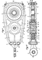
- the adapter shown comprises a first rigid element 1 intended to be connected to a helicopter blade and a second rigid element 2 intended to be made integral with a rotor.
- the elements are made of light alloy.
- the element 1 is produced in two parts 1a, 1b symmetrical with respect to the horizontal plane and the ribbed shape of which is clearly seen in FIG. 1. These parts of elements 1a and 1b extend in parallel and are connected via of a plurality of bolts 3 to a fixing lug forming part of the element 1 and having a mounting ball 4. Apart from the cracks such as 5, the parts 1a and 1b, connected to each other at the 'other end by bolts 6, have two circular passages one of larger diameter 7 and the other of smaller diameter 8, centrally arranged.
- the element 2 which has, at the center of the passage 7, a mounting ball 9 and, with regard to the passage 8, an oblong passage whose largest diameter, oriented along the longitudinal axis II-II is substantially equal to the diameter of the passage 8 while transversely, the dimension of the oblong passage is less than the diameter of the passage 8 and just slightly greater than the transverse dimension of the empty space which will be mentioned below .
- an elastomeric mass 10 adhered to said surfaces and the peripheral contour of which is seen in broken lines 11 in FIG. 1.
- the elastomeric mass is crossed by an oblong empty space of which we see the trace 12 in broken lines in FIG. 1.
- the dimensions of the oblong empty space 12 are slightly smaller than the dimensions of the oblong passage corresponding to element 2 so that the internal edge of this passage is everywhere covered by the elastomer.
- the oblong space thus created has two concave elastomeric walls 13, 14 aligned along the longitudinal axis II-II or III-III and two transverse walls 15 substantially rectilinear.
- a restriction piece 16 made in fact of two halves 16a, 16b joined by a central bolt 17.
- This piece has two circular flanges 18 which come to adjust , with the interposition of a seal, in the two openings 8 which are thus tightly sealed, the tightening of the bolt ensuring perfect attachment of the part 16 and the part 1.
- the part 16 has a central part cylindrical 19 extending between the two flanges 18 and the section of which in the horizontal plane is clearly seen in FIG. 3.
- This section has two straight edges 20, 21 oriented towards the curved walls 13, 14 and two edges in an arc of a circle 22 oriented towards the wall portions 15 of the oblong space formed in the elastomer. It can be seen that, in this way, two chambers 23, 24 have been formed of equal volumes joined by two narrow passages 25.
- each channel 27 opening out exactly at the tightest location of the corresponding passage 25 and simultaneously supplying two chambers 26.
- the major part of the chambers 26 is occupied each time by a capsule gauge 28 whose volume decreases when the pressure around it increases.
- the device according to the invention is stressed only in the longitudinal direction shown by lines II-II and III-III in FIGS. 2 and 3. Consequently, when under the effect, for example of vibrations, the internal element 2 is moves to the right in the figures, it carries with it the elastomer which works in shear and the wall 13 comes closer to the edge 20 of the part 16 while the wall 14 moves away from the edge 19, the reduction in volume of the chamber 23 thus being exactly compensated by the increase in volume of the chamber 24.
- a viscous fluid for example an oil or a grease
- a viscous fluid which has been introduced into the space available through a passage closed by a plug 29 and which occupies all the space available inside the chambers, passages, channels and internal chambers, is discharged out of the chamber 23 towards room 24 by the passa 25.
- damping effect the characteristics of which are determined by the viscosity of the fluid and the dimensions of the passages 25. It is thus possible to be satisfied with using an elastomeric material having damping capacities.
Landscapes
- Engineering & Computer Science (AREA)
- Mechanical Engineering (AREA)
- General Engineering & Computer Science (AREA)
- Aviation & Aerospace Engineering (AREA)
- Combined Devices Of Dampers And Springs (AREA)
Applications Claiming Priority (2)
| Application Number | Priority Date | Filing Date | Title |
|---|---|---|---|
| FR8210198A FR2528382A1 (fr) | 1982-06-11 | 1982-06-11 | Amortisseur de vibrations et notamment adaptateur de frequence pour pale d'helicoptere |
| FR8210198 | 1982-06-11 |
Publications (2)
| Publication Number | Publication Date |
|---|---|
| EP0097091A1 true EP0097091A1 (de) | 1983-12-28 |
| EP0097091B1 EP0097091B1 (de) | 1987-09-30 |
Family
ID=9274889
Family Applications (1)
| Application Number | Title | Priority Date | Filing Date |
|---|---|---|---|
| EP83401153A Expired EP0097091B1 (de) | 1982-06-11 | 1983-06-07 | Schwingungsdämpfer und insbesondere Frequenzanpassvorrichtung für Hubschrauberblätter |
Country Status (4)
| Country | Link |
|---|---|
| US (1) | US4566677A (de) |
| EP (1) | EP0097091B1 (de) |
| DE (1) | DE3373887D1 (de) |
| FR (1) | FR2528382A1 (de) |
Cited By (3)
| Publication number | Priority date | Publication date | Assignee | Title |
|---|---|---|---|---|
| EP0334716A1 (de) * | 1988-03-24 | 1989-09-27 | AEROSPATIALE Société Nationale Industrielle | Elastohydraulische Blattrückholvorrichtung mit linearer Dämpfung durch die Drosselung einer viskosen Flüssigkeit |
| FR2680845A1 (fr) * | 1991-09-04 | 1993-03-05 | Vibrachoc Sa | Absorbeur d'energie vibratoire. |
| EP0636810A1 (de) * | 1993-07-29 | 1995-02-01 | Hutchinson | Verbesserung an den Gegenschwingungslagern von Hubschrauberrotorflügeln, und Hubschrauberrotor mit solchen Lagern |
Families Citing this family (11)
| Publication number | Priority date | Publication date | Assignee | Title |
|---|---|---|---|---|
| FR2616122B1 (fr) * | 1987-06-04 | 1990-11-30 | Aerospatiale | Bras de liaison torsible et flexible avec amortissement de flexion integre, en particulier pour la liaison d'une pale de rotor a son moyeu, et rotor et moyeu equipes de tels bras |
| US5374039A (en) * | 1992-08-24 | 1994-12-20 | Lord Corporation | Fluid-and-elastomer support device |
| CA2149673C (en) * | 1992-12-23 | 1998-08-18 | Francis E. Byrnes | Tubular elastomer damper |
| US5913659A (en) * | 1993-11-22 | 1999-06-22 | United Technologies Corporation | Apparatus and method for adjusting rotor blade tracking |
| US5501434A (en) * | 1994-05-10 | 1996-03-26 | Lord Corporation | Hybrid fluid and elastomer damper |
| US5540549A (en) * | 1994-08-05 | 1996-07-30 | Lord Corporation | Fluid damping devices |
| US6293532B2 (en) | 1997-08-04 | 2001-09-25 | Lord Corporation | Fluid and elastomer apparatus |
| US6092795A (en) * | 1997-08-04 | 2000-07-25 | Lord Corporation | Fluid and elastomer damper |
| US6045328A (en) * | 1998-09-23 | 2000-04-04 | Lord Corporation | Fluid damper including flexible damping plate |
| US20110307018A1 (en) * | 2010-06-10 | 2011-12-15 | Spartek Medical, Inc. | Adaptive spinal rod and methods for stabilization of the spine |
| FR3057541B1 (fr) * | 2016-10-14 | 2019-03-29 | Airbus Helicopters | Amortisseur de trainee integre a l'interieur d'une pale d'un rotor |
Citations (5)
| Publication number | Priority date | Publication date | Assignee | Title |
|---|---|---|---|---|
| US3361216A (en) * | 1964-04-24 | 1968-01-02 | Westland Aircraft Ltd | Damping devices |
| FR2063969A1 (de) * | 1969-10-16 | 1971-07-16 | Sud Aviation | |
| FR2111845A1 (de) * | 1970-10-26 | 1972-06-09 | Lord Corp | |
| FR2242605A1 (en) * | 1973-08-31 | 1975-03-28 | Lochner Kaspar | Vibration damper and shock absorber |
| FR2449826A1 (fr) * | 1979-02-26 | 1980-09-19 | Textron Inc | Dispositif et procede pour empecher la transmission de vibrations d'un corps a un autre |
Family Cites Families (8)
| Publication number | Priority date | Publication date | Assignee | Title |
|---|---|---|---|---|
| US1304311A (en) * | 1918-05-15 | 1919-05-20 | Andrew Heldrich | Shock-absorber. |
| US1983259A (en) * | 1932-05-06 | 1934-12-04 | Weiland Alfred | Control mechanism for vehicles |
| US2514140A (en) * | 1947-06-17 | 1950-07-04 | Houdaille Hershey Corp | Combination linear and rotary vibration damper |
| US3403899A (en) * | 1966-04-29 | 1968-10-01 | Gen Motors Corp | Viscous damped bushing |
| US3658314A (en) * | 1969-08-18 | 1972-04-25 | Clevite Corp | Elastomeric fluid shock absorber |
| US3842945A (en) * | 1971-05-13 | 1974-10-22 | J Potter | Viscoelastic damper |
| GB1445373A (en) * | 1973-09-11 | 1976-08-11 | Arfina Anstalt Finanz | Frequency adapter particularly for a helicopter with rigid blades |
| FR2298737A1 (fr) * | 1975-01-24 | 1976-08-20 | Airlex | Dispositif pour l'amortissement d'un mouvement oscillatoire |
-
1982
- 1982-06-11 FR FR8210198A patent/FR2528382A1/fr active Granted
-
1983
- 1983-06-07 EP EP83401153A patent/EP0097091B1/de not_active Expired
- 1983-06-07 DE DE8383401153T patent/DE3373887D1/de not_active Expired
- 1983-06-08 US US06/502,236 patent/US4566677A/en not_active Expired - Fee Related
Patent Citations (5)
| Publication number | Priority date | Publication date | Assignee | Title |
|---|---|---|---|---|
| US3361216A (en) * | 1964-04-24 | 1968-01-02 | Westland Aircraft Ltd | Damping devices |
| FR2063969A1 (de) * | 1969-10-16 | 1971-07-16 | Sud Aviation | |
| FR2111845A1 (de) * | 1970-10-26 | 1972-06-09 | Lord Corp | |
| FR2242605A1 (en) * | 1973-08-31 | 1975-03-28 | Lochner Kaspar | Vibration damper and shock absorber |
| FR2449826A1 (fr) * | 1979-02-26 | 1980-09-19 | Textron Inc | Dispositif et procede pour empecher la transmission de vibrations d'un corps a un autre |
Cited By (7)
| Publication number | Priority date | Publication date | Assignee | Title |
|---|---|---|---|---|
| EP0334716A1 (de) * | 1988-03-24 | 1989-09-27 | AEROSPATIALE Société Nationale Industrielle | Elastohydraulische Blattrückholvorrichtung mit linearer Dämpfung durch die Drosselung einer viskosen Flüssigkeit |
| FR2629163A1 (fr) * | 1988-03-24 | 1989-09-29 | Aerospatiale | Contre-fiche de rappel elastique de type elasto-hydraulique a amortissement lineaire incorpore par laminage d'un fluide de viscosite elevee |
| US5004215A (en) * | 1988-03-24 | 1991-04-02 | Societe Nationale Industrielle Et Aerospatiale | Resilient return strut of the elastic-hydraulic type with incorporated linear damping by throttling a high-viscosity fluid |
| FR2680845A1 (fr) * | 1991-09-04 | 1993-03-05 | Vibrachoc Sa | Absorbeur d'energie vibratoire. |
| EP0636810A1 (de) * | 1993-07-29 | 1995-02-01 | Hutchinson | Verbesserung an den Gegenschwingungslagern von Hubschrauberrotorflügeln, und Hubschrauberrotor mit solchen Lagern |
| FR2708694A1 (fr) * | 1993-07-29 | 1995-02-10 | Hutchinson | Perfectionnement aux supports antivibratoires. |
| US5489193A (en) * | 1993-07-29 | 1996-02-06 | Hutchinson | Antivibration supports for helicopter blades, and a helicopter rotor including such supports |
Also Published As
| Publication number | Publication date |
|---|---|
| DE3373887D1 (en) | 1987-11-05 |
| FR2528382B1 (de) | 1985-01-04 |
| US4566677A (en) | 1986-01-28 |
| FR2528382A1 (fr) | 1983-12-16 |
| EP0097091B1 (de) | 1987-09-30 |
Similar Documents
| Publication | Publication Date | Title |
|---|---|---|
| EP0335786B1 (de) | Elastischer Streben mit integriertem, hydro-mechanischem Resonator, insbesondere für die Aufhängung eines Getriebes an einen Drehflügler und eine Aufhängevorrichtung mit einer solchen Verwendungsmöglichkeit | |
| FR2601098A1 (fr) | Structure de manchonnage elastique a remplissage de fluide | |
| EP0097091B1 (de) | Schwingungsdämpfer und insbesondere Frequenzanpassvorrichtung für Hubschrauberblätter | |
| FR2600738A1 (fr) | Manchonnage elastique a remplissage de fluide comportant des moyens d'amortissement dans les chambres de fluide. | |
| FR2615260A1 (fr) | Dispositif, rempli de fluide, isolant aux vibrations | |
| EP0709594B1 (de) | Verbesserungen an vibrationsdämpfenden, hydraulischen Stützen | |
| FR2492026A1 (fr) | Dispositif porteur en caoutchouc possedant une capacite d'amortissement pneumatique | |
| FR2600737A1 (fr) | Manchonnage elastique a remplissage de fluide ayant d'excellentes caracteristiques d'amortissement des vibrations axiales. | |
| EP1136719A1 (de) | Schwingungsdämpfer, insbesondere für Hubschrauberrotor | |
| FR2624235A1 (fr) | Manchonnage elastique a remplissage de fluide comportant des moyens de limitation de la deformation elastique des extremites axiales de l'element elastique definissant la chambre de reception de pression | |
| FR2524951A1 (fr) | Support amortissant | |
| EP0437137B1 (de) | Hydraulisch gedämpfte Lagerbuchsen | |
| FR2628805A1 (fr) | Structure de montage elastique a remplissage de fluide a elements mobiles et a orifices | |
| FR2495718A1 (fr) | Support amortisseur, notamment pour moteur a combustion interne de vehicule automobile | |
| EP1489335B1 (de) | Hydraulisches, schwingungsdämpfendes Lager | |
| EP0636810B1 (de) | Verbesserung an den Gegenschwingungslagern von Hubschrauberrotorflügeln, und Hubschrauberrotor mit solchen Lagern | |
| EP1645773B1 (de) | Hydraulisches schwingungsdämpfendes Lager für ein Kraftfahrzeug und Herstellungsverfahren einer solchen Vorrichtung | |
| FR2973463A1 (fr) | Dispositif d'amortissement de vibration rempli de fluide du type a amortissement de vibration multidirectionnel | |
| EP1387111B1 (de) | Hydraulisch gedämpftes elastisches Lager | |
| FR2914716A1 (fr) | Butee de compression hydraulique, notamment pour amortisseur hydraulique de suspension de vehicule automobile | |
| FR2655113A1 (fr) | Dispositif d'amortissement en elastomere rempli d'un fluide. | |
| EP3781835B1 (de) | Fluiddämpfer mit flüssigkeitsbasierter trägheitsdämpfung für eine fahrzeugfederung | |
| FR2736890A1 (fr) | Amortisseur hydroelastique de trainee pour rotor de giravion | |
| FR2739424A1 (fr) | Support elastique cylindrique rempli de fluide comprenant un manchon intermediaire en resine synthetique comportant des butees formees d'un seul tenant avec le manchon | |
| FR2739668A1 (fr) | Dispositif perfectionne d'obturation a guide centreur lubrifie pour tube d'amortisseur hydraulique pressurise |
Legal Events
| Date | Code | Title | Description |
|---|---|---|---|
| PUAI | Public reference made under article 153(3) epc to a published international application that has entered the european phase |
Free format text: ORIGINAL CODE: 0009012 |
|
| AK | Designated contracting states |
Designated state(s): DE GB IT |
|
| 17P | Request for examination filed |
Effective date: 19840403 |
|
| GRAA | (expected) grant |
Free format text: ORIGINAL CODE: 0009210 |
|
| AK | Designated contracting states |
Kind code of ref document: B1 Designated state(s): DE GB IT |
|
| ITF | It: translation for a ep patent filed | ||
| REF | Corresponds to: |
Ref document number: 3373887 Country of ref document: DE Date of ref document: 19871105 |
|
| GBT | Gb: translation of ep patent filed (gb section 77(6)(a)/1977) | ||
| PLBE | No opposition filed within time limit |
Free format text: ORIGINAL CODE: 0009261 |
|
| STAA | Information on the status of an ep patent application or granted ep patent |
Free format text: STATUS: NO OPPOSITION FILED WITHIN TIME LIMIT |
|
| 26N | No opposition filed | ||
| ITTA | It: last paid annual fee | ||
| PGFP | Annual fee paid to national office [announced via postgrant information from national office to epo] |
Ref country code: GB Payment date: 19950502 Year of fee payment: 13 |
|
| PGFP | Annual fee paid to national office [announced via postgrant information from national office to epo] |
Ref country code: DE Payment date: 19950529 Year of fee payment: 13 |
|
| PG25 | Lapsed in a contracting state [announced via postgrant information from national office to epo] |
Ref country code: GB Effective date: 19960607 |
|
| GBPC | Gb: european patent ceased through non-payment of renewal fee |
Effective date: 19960607 |
|
| PG25 | Lapsed in a contracting state [announced via postgrant information from national office to epo] |
Ref country code: DE Effective date: 19970301 |