EP0097123A2 - Relais électromagnétique miniaturisé - Google Patents
Relais électromagnétique miniaturisé Download PDFInfo
- Publication number
- EP0097123A2 EP0097123A2 EP83810249A EP83810249A EP0097123A2 EP 0097123 A2 EP0097123 A2 EP 0097123A2 EP 83810249 A EP83810249 A EP 83810249A EP 83810249 A EP83810249 A EP 83810249A EP 0097123 A2 EP0097123 A2 EP 0097123A2
- Authority
- EP
- European Patent Office
- Prior art keywords
- contact
- pole
- magnetically
- relay
- poles
- Prior art date
- Legal status (The legal status is an assumption and is not a legal conclusion. Google has not performed a legal analysis and makes no representation as to the accuracy of the status listed.)
- Withdrawn
Links
- 239000012528 membrane Substances 0.000 claims abstract description 44
- 230000005291 magnetic effect Effects 0.000 claims abstract description 36
- 230000004907 flux Effects 0.000 claims abstract description 19
- 239000003302 ferromagnetic material Substances 0.000 claims description 9
- 230000005294 ferromagnetic effect Effects 0.000 claims description 8
- 239000000696 magnetic material Substances 0.000 claims 1
- 239000006187 pill Substances 0.000 abstract description 16
- 239000004020 conductor Substances 0.000 abstract description 2
- 230000000694 effects Effects 0.000 abstract description 2
- 210000004379 membrane Anatomy 0.000 description 41
- 229910052751 metal Inorganic materials 0.000 description 4
- 239000002184 metal Substances 0.000 description 4
- 230000004927 fusion Effects 0.000 description 3
- 239000011521 glass Substances 0.000 description 3
- 238000000034 method Methods 0.000 description 3
- 230000035945 sensitivity Effects 0.000 description 3
- 230000008878 coupling Effects 0.000 description 2
- 238000010168 coupling process Methods 0.000 description 2
- 238000005859 coupling reaction Methods 0.000 description 2
- 239000000203 mixture Substances 0.000 description 2
- 238000003466 welding Methods 0.000 description 2
- 239000000853 adhesive Substances 0.000 description 1
- 230000001070 adhesive effect Effects 0.000 description 1
- 230000015556 catabolic process Effects 0.000 description 1
- 239000000919 ceramic Substances 0.000 description 1
- 239000011248 coating agent Substances 0.000 description 1
- 238000000576 coating method Methods 0.000 description 1
- 230000007547 defect Effects 0.000 description 1
- 230000001419 dependent effect Effects 0.000 description 1
- 238000011161 development Methods 0.000 description 1
- 230000018109 developmental process Effects 0.000 description 1
- 230000005489 elastic deformation Effects 0.000 description 1
- 238000009434 installation Methods 0.000 description 1
- 238000012544 monitoring process Methods 0.000 description 1
- 229910000510 noble metal Inorganic materials 0.000 description 1
Images

Classifications
-
- H—ELECTRICITY
- H01—ELECTRIC ELEMENTS
- H01H—ELECTRIC SWITCHES; RELAYS; SELECTORS; EMERGENCY PROTECTIVE DEVICES
- H01H51/00—Electromagnetic relays
- H01H51/22—Polarised relays
-
- H—ELECTRICITY
- H01—ELECTRIC ELEMENTS
- H01H—ELECTRIC SWITCHES; RELAYS; SELECTORS; EMERGENCY PROTECTIVE DEVICES
- H01H51/00—Electromagnetic relays
- H01H51/22—Polarised relays
- H01H51/2209—Polarised relays with rectilinearly movable armature
-
- H—ELECTRICITY
- H01—ELECTRIC ELEMENTS
- H01H—ELECTRIC SWITCHES; RELAYS; SELECTORS; EMERGENCY PROTECTIVE DEVICES
- H01H50/00—Details of electromagnetic relays
- H01H50/54—Contact arrangements
- H01H50/56—Contact spring sets
Definitions
- the present invention relates to an electromagnetic miniature relay according to the preamble of the first claim.
- Electromagnetic relays in which membrane contacts are used as contact units, are known and e.g. in CH-Pat.Nr. 455 941 described in detail. Contact units of this type are in particular from CH-Pat.Nr. 452 021, in which different membrane and contact configurations are described with regard to their use for a make, break or changeover contact. It is also known to use permanent magnets in relays in order to achieve magnetic adhesion of the contacts after the control flow has been removed and / or a higher sensitivity of the relay. A relay with magnetic adhesion is e.g. in CH-Pat.Nr. 498 482. Permanent magnets to improve sensitivity have already been used in the polarized relays for telegraphy reception that have been known for decades.
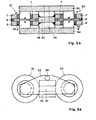
- the contact unit known from the prior art will now be described with reference to FIGS. 1 and 2 to the extent that it appears necessary for an understanding of the present invention.
- the contact unit has a circular membrane 1 made of ferromagnetic, electrically conductive material with an edge zone 2, a spring zone 3 and a contact zone 4.
- the edge zone 2 of the membrane 1 is connected to pole rings 7 and 8 via intermediate rings 9, this connection advantageously being made by welding.
- the membrane 1 forms the movable contact and the two poles 5 and 6 are the fixed contacts of a changeover contact.
- the surfaces of the contacting parts of the membrane and the poles can be designed according to their function, e.g. the contact surfaces can have a noble metal coating.
- the membrane 1 can, as shown in Fig. 1, be arranged in the central position between the two poles, but the intermediate rings can also have different heights, so that the membrane is closer to one or the other pole in the case of a contact unit which is not built into a magnetic circuit , which results in a different spring force in the two contact positions during operation.
- the intermediate rings can also be designed so that the membrane is at rest on a pole with a certain pressure rests so that the normally closed contact of a changeover contact results.
- the welding of the membrane, intermediate rings and pole rings and the glass / metal fusion of the pole rings with the associated poles results in a hermetically sealed contact space that can be made empty or provided with a gas filling of the desired composition.
- the contact unit is referred to in the following for its shape and size as a contact pill.
- 3a and 3b show the basic structure of a bistable relay with two changeover contacts.
- the relay has two contact pills 31 and 32, which have a structure according to FIGS. 1 and 2 and the individual parts of which are designated with the same reference numerals as in this figure for pill 31 and with 'addition for pill 32.
- the contact between membrane 1 and pole 5 is denoted by a and that between membrane 1 and pole 6 is denoted by b, while for pill 32, the corresponding contacts are denoted by a 'and b'.
- the poles 5 and 5 'of the contact pills 31, respectively. 32 are magnetically but not electrically connected to a yoke 33 made of ferromagnetic material.
- the poles 6 and 6 ' are connected to a yoke 34.
- the pole rings 7 and 8 of the contact pill 31 are also magnetically but not electrically conductively connected to the pole rings 7 'and 8' of the contact pill 32 via a ferromagnetic core 37 of a control coil 36.
- a permanent magnet 35 is connected to the yokes 33 and 34 in such a way that one of its poles abuts one of these yokes.
- the flux of the permanent magnet 35 flows from the pole rings 7/8 through the coil core 37 to the pole rings 7 '/ 8'.
- the control coil 36 must therefore generate a flow in the opposite direction, ie from the pole rings 7 '/ 8' to the pole rings 7/8, so that there is a north pole at 7/8 and a south pole at 7 '/ 8'.
- the contact pressure between the membrane 1 and the corresponding pole is at rest, ie when the coil 36 is switched off, determined by the attraction force caused by the flow of the permanent magnet 35 minus the spring force of the membrane 1, because its contact zone 4 with elastic deformation of the spring zone 3 from the middle position between the poles 5 and 6 is deflected.
- the spring force of zone 3 of the diaphragm 1 contributes to increasing the sensitivity of the relay, because the flow of the control coil 36 only has to generate an attractive force that is not much greater than the contact pressure.
- the two contact pills are magnetically connected in series, there is a magnetic coupling of the two changeover contacts, so that one changeover contact can be used to monitor the other, which is sometimes desirable in the case of bistable holding relays. Even if the monitored contact should stick in one of its positions due to a defect, the monitoring contact resumes the position corresponding to the adhesive contact after the control signal has been switched off.
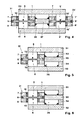
- FIGS. 4-6 each of which shows a section through the relay, the same reference symbols being used for the same parts as in previous figures.
- the floor plan, not shown, can be analogous to that of FIG. 3a.
- Fig. 4 shows a monostable relay with permanent magnet and two changeover contacts.
- This relay has the same structure as that according to FIG. 3, with the exception that the permanent magnet 35 present in FIG. 3 between the yokes 33 and 34 is omitted and that the ferromagnetic yoke 34 is replaced by a permanent magnetic yoke 41.
- contacts b and b ' are closed. If the north pole of the permanent magnet 41 abuts the pole 6, the following magnetic flux results: north pole of the permanent magnet 41, pole 6, membrane 1, pole rings 7/8, coil core 37, pole rings 7 '/ 8', membrane 1 ', pole 6', South pole of magnet 41.
- the two poles 5, 6 are each connected via a yoke 51, 52 made of ferromagnetic material to opposite poles of two permanent magnets 53, 54.
- the other poles of these magnets are connected to the core 55 of the control coil 36 in a magnetically conductive manner. In each of the two contact positions, the magnetic circuit for one of these permanent magnets is closed and open for the other.
- the two permanent magnets 53 and 54 could also be replaced by a single permanent magnet, the center of which is magnetically connected to the core 55, in order to achieve the same effect.
- 6 shows a monostable relay with a permanent magnet and a single changeover contact. The structure is similar to that of FIG. 5, but the yoke 51 in series with the permanent magnet 53 of FIG. 5 is replaced by a single yoke 61 made of ferromagnetic material. When the control coil 36 is not energized, the magnetic circuit for the permanent magnetic flux is exactly the same as that of the relay according to FIG. 5 when its contact b is closed.
- the present relays have very small dimensions and no moving parts, with the exception of the membranes arranged in the hermetically sealed contact pills, they can be poured into integrated DIL housings like integrated circuits, with the current-carrying parts of the contact pills and the connections of the control coil being matched accordingly external connections must be made.
- the relays described result in a relay family which all use the same, completely sealed contact pill, which can be empty or filled with a gas filling of the desired composition.
- the achievable breakdown voltage of the contacts can reach values above 1 kV. Thanks to the use of a permanent magnet, whose magnetic circuit is only closed over the coil core, the relays only need one control power of approx. 30 mW, so that it can be directly controlled by the output signals of standard TTL circuits. Relays with two changeover contacts have a magnetic coupling of the contacts.
- the membranes as the only movable elements have a very low mass, which leads to short switching and bounce times and a long service life.
- the small dimensions that enable the relay to be installed in standard DIL housings that are common in integrated circuits allow space-saving installation of the relays together with integrated circuits on printed circuit boards.
Landscapes
- Physics & Mathematics (AREA)
- Electromagnetism (AREA)
- Electromagnets (AREA)
- Relay Circuits (AREA)
- Switches Operated By Changes In Physical Conditions (AREA)
Applications Claiming Priority (2)
| Application Number | Priority Date | Filing Date | Title |
|---|---|---|---|
| CH357982 | 1982-06-10 | ||
| CH3579/82 | 1982-06-10 |
Publications (2)
| Publication Number | Publication Date |
|---|---|
| EP0097123A2 true EP0097123A2 (fr) | 1983-12-28 |
| EP0097123A3 EP0097123A3 (fr) | 1986-10-01 |
Family
ID=4259035
Family Applications (1)
| Application Number | Title | Priority Date | Filing Date |
|---|---|---|---|
| EP83810249A Withdrawn EP0097123A3 (fr) | 1982-06-10 | 1983-06-08 | Relais électromagnétique miniaturisé |
Country Status (13)
| Country | Link |
|---|---|
| US (1) | US4503410A (fr) |
| EP (1) | EP0097123A3 (fr) |
| JP (1) | JPS5958732A (fr) |
| KR (1) | KR840005268A (fr) |
| AU (1) | AU561444B2 (fr) |
| BE (1) | BE897016A (fr) |
| BR (1) | BR8303039A (fr) |
| CA (1) | CA1203824A (fr) |
| ES (1) | ES281213Y (fr) |
| IT (1) | IT1164271B (fr) |
| MX (1) | MX153537A (fr) |
| NZ (1) | NZ204426A (fr) |
| PH (1) | PH20524A (fr) |
Families Citing this family (2)
| Publication number | Priority date | Publication date | Assignee | Title |
|---|---|---|---|---|
| US7115825B2 (en) * | 2001-02-15 | 2006-10-03 | Integral Technologies, Inc. | Low cost key actuators and other switching device actuators manufactured from conductive loaded resin-based materials |
| US20110024275A1 (en) * | 2001-02-16 | 2011-02-03 | Integral Technologies, Inc. | Low cost key actuators and other switching device actuators manufactured from conductive loaded resin-based materials |
Family Cites Families (8)
| Publication number | Priority date | Publication date | Assignee | Title |
|---|---|---|---|---|
| GB1219556A (en) * | 1969-06-06 | 1971-01-20 | Standard Telephones Cables Ltd | Improvements in or relating to magnetic contact units |
| BE756309R (fr) * | 1969-09-18 | 1971-03-18 | Int Standard Electric Corp | Elektromagnetisch bediend relais |
| US3621419A (en) * | 1970-02-19 | 1971-11-16 | Leach Corp | Polarized latch relay |
| GB1341671A (en) * | 1972-01-06 | 1973-12-25 | Standard Telephones Cables Ltd | Changeover operation contact units |
| DE2258922C3 (de) * | 1972-12-01 | 1980-03-06 | Standard Elektrik Lorenz Ag, 7000 Stuttgart | Magnetisch betätigbarer, abgeschlossener Kontakt mit einem flachen Gehäuse |
| DE2306522B1 (de) * | 1973-02-09 | 1974-06-20 | Standard Elektrik Lorenz Ag, 7000 Stuttgart | Magnetisch betätigbarer, abgeschlossener Kontakt |
| DE7733950U1 (de) * | 1976-11-15 | 1981-04-02 | Iskra ZP Ljubljana o.sub. o., Ljubljana | Elektromagnetisches Umschlagrelais |
| YU40325B (en) * | 1978-02-27 | 1985-12-31 | Iskra | Miniature relay for short switching-over time |
-
1983
- 1983-05-31 NZ NZ204426A patent/NZ204426A/en unknown
- 1983-06-03 PH PH29014A patent/PH20524A/en unknown
- 1983-06-06 AU AU15378/83A patent/AU561444B2/en not_active Expired - Fee Related
- 1983-06-06 MX MX197552A patent/MX153537A/es unknown
- 1983-06-07 US US06/501,934 patent/US4503410A/en not_active Expired - Fee Related
- 1983-06-08 BR BR8303039A patent/BR8303039A/pt unknown
- 1983-06-08 IT IT21525/83A patent/IT1164271B/it active
- 1983-06-08 EP EP83810249A patent/EP0097123A3/fr not_active Withdrawn
- 1983-06-08 JP JP58101041A patent/JPS5958732A/ja active Granted
- 1983-06-09 CA CA000430000A patent/CA1203824A/fr not_active Expired
- 1983-06-10 ES ES1983281213U patent/ES281213Y/es not_active Expired
- 1983-06-10 BE BE2/60127A patent/BE897016A/fr not_active IP Right Cessation
- 1983-06-10 KR KR1019830002583A patent/KR840005268A/ko not_active Withdrawn
Also Published As
| Publication number | Publication date |
|---|---|
| MX153537A (es) | 1986-11-11 |
| NZ204426A (en) | 1986-08-08 |
| IT8321525A0 (it) | 1983-06-08 |
| AU561444B2 (en) | 1987-05-07 |
| ES281213Y (es) | 1986-04-16 |
| BE897016A (fr) | 1983-12-12 |
| ES281213U (es) | 1985-08-01 |
| IT1164271B (it) | 1987-04-08 |
| AU1537883A (en) | 1983-12-15 |
| IT8321525A1 (it) | 1984-12-08 |
| JPS5958732A (ja) | 1984-04-04 |
| JPH0414453B2 (fr) | 1992-03-12 |
| BR8303039A (pt) | 1984-01-31 |
| CA1203824A (fr) | 1986-04-29 |
| PH20524A (en) | 1987-01-30 |
| EP0097123A3 (fr) | 1986-10-01 |
| KR840005268A (ko) | 1984-11-05 |
| US4503410A (en) | 1985-03-05 |
Similar Documents
| Publication | Publication Date | Title |
|---|---|---|
| EP1032941B1 (fr) | Relais miniaturise a bobine plate | |
| DE1154870B (de) | Elektromagnetisch gesteuertes Schaltgeraet | |
| EP0097123A2 (fr) | Relais électromagnétique miniaturisé | |
| DE1194497B (de) | Elektromagnetische Schaltvorrichtung mit Schutzrohrankerkontakt | |
| DE1935955A1 (de) | Elektromagnetisches Relais | |
| DE1046779B (de) | Gepolter Schutzrohrwechselkontakt | |
| DE3149816A1 (de) | Polarisiertes relais | |
| DE2045831A1 (de) | Elektromagnetisches Relais | |
| CH522285A (de) | Stromstoss-Schalter | |
| EP0068391A2 (fr) | Relais electromagnétique polarisé miniaturisé | |
| EP0089973B1 (fr) | Relais electromagnetique bistable a impulsion | |
| DE917135C (de) | Schaltpatrone | |
| DE1951805A1 (de) | Elektromagnetisches Relais | |
| DE640911C (de) | Elektromagnetisch gesteuertes Schauzeichen als Rueckmelder in Fernbedienungsanlagen | |
| DE1104064B (de) | Mehrfachrelais | |
| DE3135360A1 (de) | Elektromagnetisches schaltgeraet | |
| DE2400392A1 (de) | Elektrisch betaetigtes ventil | |
| DE1615975C3 (de) | Bistabiler Quecksilberkontakt für Anordnungen der Fernmelde-, Steuerungsund Informationstechnik, insbesondere für Koppelfeldanordnungen | |
| DE2104258B1 (de) | Elektromagnetisch betätigbare Schalteinrichtung | |
| AT208445B (de) | Gepoltes elektromagnetisches Relais | |
| AT216081B (de) | Elektrischer Schalter | |
| EP0167942B1 (fr) | Relais électromagnétique miniature polarisé | |
| DE212197C (fr) | ||
| DE1764867C (de) | Elektrisches Relais mit quecksilberbenetztem Anker-Kontakt | |
| DE1926786U (de) | Gepoltes relais mit gekapselter kontakteinrichtung. |
Legal Events
| Date | Code | Title | Description |
|---|---|---|---|
| PUAI | Public reference made under article 153(3) epc to a published international application that has entered the european phase |
Free format text: ORIGINAL CODE: 0009012 |
|
| AK | Designated contracting states |
Designated state(s): AT CH FR GB LI NL SE |
|
| RBV | Designated contracting states (corrected) |
Designated state(s): AT CH FR GB LI NL SE |
|
| 17P | Request for examination filed |
Effective date: 19840315 |
|
| PUAL | Search report despatched |
Free format text: ORIGINAL CODE: 0009013 |
|
| AK | Designated contracting states |
Kind code of ref document: A3 Designated state(s): AT CH FR GB LI NL SE |
|
| STAA | Information on the status of an ep patent application or granted ep patent |
Free format text: STATUS: THE APPLICATION IS DEEMED TO BE WITHDRAWN |
|
| 18D | Application deemed to be withdrawn |
Effective date: 19870402 |
|
| RIN1 | Information on inventor provided before grant (corrected) |
Inventor name: HOCHREUTINER, ROGER MAURICE |