EP0097257A2 - Méthode et appareil pour réaliser une source de lumière de forme reguise - Google Patents
Méthode et appareil pour réaliser une source de lumière de forme reguise Download PDFInfo
- Publication number
- EP0097257A2 EP0097257A2 EP83105174A EP83105174A EP0097257A2 EP 0097257 A2 EP0097257 A2 EP 0097257A2 EP 83105174 A EP83105174 A EP 83105174A EP 83105174 A EP83105174 A EP 83105174A EP 0097257 A2 EP0097257 A2 EP 0097257A2
- Authority
- EP
- European Patent Office
- Prior art keywords
- hologram
- light source
- desired shape
- source
- playback
- Prior art date
- Legal status (The legal status is an assumption and is not a legal conclusion. Google has not performed a legal analysis and makes no representation as to the accuracy of the status listed.)
- Granted
Links
Images

Classifications
-
- G—PHYSICS
- G02—OPTICS
- G02B—OPTICAL ELEMENTS, SYSTEMS OR APPARATUS
- G02B5/00—Optical elements other than lenses
- G02B5/32—Holograms used as optical elements
-
- G—PHYSICS
- G03—PHOTOGRAPHY; CINEMATOGRAPHY; ANALOGOUS TECHNIQUES USING WAVES OTHER THAN OPTICAL WAVES; ELECTROGRAPHY; HOLOGRAPHY
- G03F—PHOTOMECHANICAL PRODUCTION OF TEXTURED OR PATTERNED SURFACES, e.g. FOR PRINTING, FOR PROCESSING OF SEMICONDUCTOR DEVICES; MATERIALS THEREFOR; ORIGINALS THEREFOR; APPARATUS SPECIALLY ADAPTED THEREFOR
- G03F7/00—Photomechanical, e.g. photolithographic, production of textured or patterned surfaces, e.g. printing surfaces; Materials therefor, e.g. comprising photoresists; Apparatus specially adapted therefor
- G03F7/70—Microphotolithographic exposure; Apparatus therefor
- G03F7/70058—Mask illumination systems
- G03F7/70091—Illumination settings, i.e. intensity distribution in the pupil plane or angular distribution in the field plane; On-axis or off-axis settings, e.g. annular, dipole or quadrupole settings; Partial coherence control, i.e. sigma or numerical aperture [NA]
-
- G—PHYSICS
- G03—PHOTOGRAPHY; CINEMATOGRAPHY; ANALOGOUS TECHNIQUES USING WAVES OTHER THAN OPTICAL WAVES; ELECTROGRAPHY; HOLOGRAPHY
- G03F—PHOTOMECHANICAL PRODUCTION OF TEXTURED OR PATTERNED SURFACES, e.g. FOR PRINTING, FOR PROCESSING OF SEMICONDUCTOR DEVICES; MATERIALS THEREFOR; ORIGINALS THEREFOR; APPARATUS SPECIALLY ADAPTED THEREFOR
- G03F7/00—Photomechanical, e.g. photolithographic, production of textured or patterned surfaces, e.g. printing surfaces; Materials therefor, e.g. comprising photoresists; Apparatus specially adapted therefor
- G03F7/70—Microphotolithographic exposure; Apparatus therefor
- G03F7/70058—Mask illumination systems
- G03F7/7015—Details of optical elements
-
- G—PHYSICS
- G02—OPTICS
- G02B—OPTICAL ELEMENTS, SYSTEMS OR APPARATUS
- G02B13/00—Optical objectives specially designed for the purposes specified below
- G02B13/22—Telecentric objectives or lens systems
Definitions
- the invention relates to a method and apparatus for producing a light source of requires shape and specifically concerns a holographic illumination system to create a continuous self-luminous source of arbitrary shape and numerical aperture.
- a copending application No. 82102516.0 discloses optical lithography apparatus having a pulsed rare gas halide excimer laser light source. This apparatus is capable of producing uniform exposure of a pattern at very fine resolution in an exposure time substantially faster than prior art systems.
- the pulsed excimer laser light source disclosed in that application produces a nearly collimated beam which is unsuitable for use in prior art projection systems which have been designed to utilize illumination through an arbitrary shape such as a curved slit.
- the principal object of this invention to provide apparatus for transforming a light beam such as a pulsed laser light beam, for example, into an optically equivalent self-luminous source of arbitrary shape and numerical aperture.
- apparatus for producing a line source of a desired shape from a monochromatic light source comprising means for directing the monochromatic light source along a predetermined path, means to position a hologram in a fixed position along the predetermined path so that the monochromatic light beam impinges upon the hologram at a predetermined angle.
- the hologram is formed by interference between a first and a second beam derived from the same source of coherent radiation, the first and second beams being directed by first and second optical means to a photosensitive medium, the second optical means including diffuser means preceded by mask means having a central opening having a continuous aperture of the desired shape, the interference between the first and second beam being recorded in the photosensitive medium to produce the hologram.
- the predetermined angle of the monochromatic light beam is chosen so that playback of the recorded hologram produces a continuous self-luminous source of the desired shape.
- the invention produces the advantage that pulsed laser light sources as well as other monochromatic sources can be easily adapted for use with existing prior art optical lithography systems so that much higher production rates can be achieved from this existing equipment.
- the specific embodiment of the invention shown in FIG. 1A comprises means for directing a beam 10 from a monochromatic light source is directed along a predetermined path as shown by the arrows to impinge on a hologram 12.
- Means fix the hologram in position along the predetermined path so that the beam impinges on the hologram at a selected angle.
- the angle and the beam 10 are selected so that beam 10 is the conjugate of the recording reference beam (shown in dashed line in FIG. lA) used to record the hologram.
- the preferred light source for beam 10 is an excimer laser. In cases where a field lens was used in recording the hologram, a field lens 16 must also be used in the playback system.
- the light pattern 14 of a desired shape and numerical aperture is reconstructed from hologram 10.
- the pattern of the desired shape is defined when the hologram is fabricated as will be described below.
- hologram 12 is a reflection relief hologram.
- the system is also operable when using a transmission hologram 12' as shown in FIG. 1B.
- beam 10 is the conjugate of the recording reference beam which is shown dotted in FIG. 1B.
- the light pattern 14 comprises a continuous self-luminous source, each point of which radiates into a finite numerical aperture defined by the cone of light of cone angle a.
- the curved arc shape of the light pattern in this specific embodiment is chosen to match the shape produced by the light source used for an existing optical apparatus comprising a system designed to utilize and project that shaped light source, e.g. a projection lithography tool.
- FIG. 3 One apparatus and method for fabricating hologram 12 is shown in FIG. 3.
- the apparatus utilizes an input beam 20 which must be temporally and spatially coherent.
- the preferred light source for beam 20 is a cw frequency doubled dye laser chosen so that its operating wavelength is the same as the wavelength of the light source to be used in playback such as beam 10 in FIG. 1.
- Input beam 20 is directed to a conventional beamsplitter 22 which divides beam 20 into a recording reference beam 24 and an object beam 26.
- a suitable substrate 28, upon which hologram 12 is formed, is fixed in position and provided with a coating 30 of a photosensitive material such as a conventional photoresist material, for example.
- a mask member 17 having an aperture 18 to define the desired numerical aperture is mounted adjacent to the coated substrate 28.
- Recording reference beam 24 is directed toward the photoresist covered substrate over a first path which includes a reflective element 32 so that recording reference beam 24 impinges on the substrate at an angle B.
- the object beam 26 is directed over a second optical path which includes reflective element 34 to direct the beam to a diffuser plate 36.
- the diffuser plate (see FIG. 4) is made from a suitable scattering plate 38 such as UV grade quartz with fine scattering centres, for example. Scattering plate 38 is covered with an opaque material in all areas except for the continuous area 40 which defines the desired shape and, in the specific embodiment shown, the desired shape is a curved slit.
- the curved diffusing area defined by area 40 now acts as a self-luminous source radiating into a large solid angle.
- the aperture 18 limits the numerical aperture to the chosen value so that only portion 48 of beam 26 is used in recording the hologram.
- the interference between beams 24 and 48 produces an interference pattern which exposes the photoresist material. After development, the interference pattern acts as a relief hologram.
- a reflective coating such as a thin layer of aluminium, for example, is then deposited on the surface of the hologram to form a reflection relief hologram.
- the hologram can further be protected by an appropriate overcoat such as magnesium fluoride, for example.
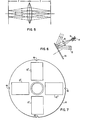
- a field lens 42 is positioned within the path of the object beam substantially midway between diffuser plate 36 and the hologram 12 surface so that the diffuser plate 36 and hologram 12 surface are located in the front and back focal planes of the lens 42.
- the diffuser plate produces a series of point sources, each point of which radiates into a finite numerical aperture. Three points are shown in FIG. 5, each of which radiates a cone of light having its principal ray substantially perpendicular to the diffuser screen surface. The upper point produces a cone of light (shown dotted in the drawing) which is directed by field lens 40 to the hologram at an angle.
- the central point (shown as a dot dashed line in the drawing) has its principal ray unaffected by the field lens and the outer rays are parallel to the principal ray.
- the lower point (shown in dash lines in the drawing) has its principal ray and the outer rays directed at an angle by the field lens so that they are parallel as they approach the hologram surface.
- the reconstructed points produce rays as shown in the drawing so that the rays converge to a point in the plane of the diffuser plate with the principal ray perpendicular to the plane of the diffuser plate. This reconstructed beam is operable with those systems which have a telecentricity requirement for the light source.
- a plurality of holograms 12" are mounted on a rotating disk 44.
- Each of the holograms 12" is preferably recorded with a different numerical aperture.
- Disk 44 (see FIG. 7) is provided with a series of detent notches 46 so that each of the holograms 12" can be selectively positioned as the operative hologram in the system.
- the detent mechanism holds the selected hologram 12" in precise alignment with the input light beam 10.
- apparatus for producing a line source of a desired shape from a light source such as a laser comprising means for directing the light source along a predetermined path as a playback beam to impinge upon a hologram at a predetermined angle to produce a continuous self- luminous source of the desired shape.
- the hologram is recorded upon a substrate coated with a photosensitive material by interference between recording and object beams derived from the same source of coherent radiation.
- the recording beam is directed toward the substrate at an orientation and angle so that the playback beam is a conjugate of the recording beam.
- the object beam is directed to the substrate over a path which includes a diffuser plate covered with an opaque material in all areas except for a continuous area which defines the desired shape.
- the part of the object beam which impinges upon the substrate is limited by an aperture which defines the numerical aperture.
Landscapes
- Physics & Mathematics (AREA)
- General Physics & Mathematics (AREA)
- Optics & Photonics (AREA)
- Holo Graphy (AREA)
- Exposure Of Semiconductors, Excluding Electron Or Ion Beam Exposure (AREA)
Applications Claiming Priority (2)
| Application Number | Priority Date | Filing Date | Title |
|---|---|---|---|
| US06/391,100 US4444456A (en) | 1982-06-23 | 1982-06-23 | Holographic method and apparatus for transformation of a light beam into a line source of required curvature and finite numerical aperture |
| US391100 | 1982-06-23 |
Publications (3)
| Publication Number | Publication Date |
|---|---|
| EP0097257A2 true EP0097257A2 (fr) | 1984-01-04 |
| EP0097257A3 EP0097257A3 (en) | 1987-01-07 |
| EP0097257B1 EP0097257B1 (fr) | 1989-04-12 |
Family
ID=23545241
Family Applications (1)
| Application Number | Title | Priority Date | Filing Date |
|---|---|---|---|
| EP83105174A Expired EP0097257B1 (fr) | 1982-06-23 | 1983-05-25 | Méthode et appareil pour réaliser une source de lumière de forme reguise |
Country Status (4)
| Country | Link |
|---|---|
| US (1) | US4444456A (fr) |
| EP (1) | EP0097257B1 (fr) |
| JP (1) | JPS58224370A (fr) |
| DE (1) | DE3379597D1 (fr) |
Cited By (2)
| Publication number | Priority date | Publication date | Assignee | Title |
|---|---|---|---|---|
| EP0127045A3 (en) * | 1983-05-23 | 1986-10-22 | International Business Machines Corporation | Apparatus for producing a light source of required shape |
| WO1988005181A1 (fr) * | 1987-01-06 | 1988-07-14 | Hughes Aircraft Company | Dispositif holographique desaxe pour l'eclairage d'un tableau de bord |
Families Citing this family (12)
| Publication number | Priority date | Publication date | Assignee | Title |
|---|---|---|---|---|
| US5310624A (en) * | 1988-01-29 | 1994-05-10 | Massachusetts Institute Of Technology | Integrated circuit micro-fabrication using dry lithographic processes |
| US5455850A (en) * | 1991-11-01 | 1995-10-03 | The Regents Of The Univerity Of Calif. | X-ray lithography using holographic images |
| US6144470A (en) * | 1997-02-24 | 2000-11-07 | O. R. Technology, Inc. | Holographic optical element with castellated aperture |
| US6671035B2 (en) * | 1999-09-29 | 2003-12-30 | Asml Netherlands B.V. | Illuminator for a lithography apparatus, a lithography apparatus comprising such an illuminator, and a manufacturing method employing such a lithography apparatus |
| TW546550B (en) * | 1999-12-13 | 2003-08-11 | Asml Netherlands Bv | An illuminator for a lithography apparatus, a lithography apparatus comprising such an illuminator, and a manufacturing method employing such a lithography apparatus |
| US6830877B2 (en) * | 2001-12-31 | 2004-12-14 | Taiwan Semiconductor Manufacturing Co., Ltd. | Method for forming via and contact holes with deep UV photoresist |
| US7911584B2 (en) * | 2003-07-30 | 2011-03-22 | Carl Zeiss Smt Gmbh | Illumination system for microlithography |
| US7081956B1 (en) * | 2003-12-04 | 2006-07-25 | Advanced Micro Devices, Inc. | Method and device for determining reflection lens pupil transmission distribution and illumination intensity distribution in reflective imaging system |
| US20050275841A1 (en) * | 2004-06-09 | 2005-12-15 | Asml Netherlands B.V. | Alignment marker and lithographic apparatus and device manufacturing method using the same |
| JP7191504B2 (ja) * | 2017-07-14 | 2022-12-19 | 株式会社Screenホールディングス | 熱処理装置 |
| JP2019021828A (ja) * | 2017-07-20 | 2019-02-07 | 株式会社Screenホールディングス | 熱処理装置 |
| US10930075B2 (en) | 2017-10-16 | 2021-02-23 | Microsoft Technology Licensing, Llc | User interface discovery and interaction for three-dimensional virtual environments |
Family Cites Families (9)
| Publication number | Priority date | Publication date | Assignee | Title |
|---|---|---|---|---|
| US3578845A (en) * | 1968-02-12 | 1971-05-18 | Trw Inc | Holographic focusing diffraction gratings for spectroscopes and method of making same |
| US3630593A (en) * | 1970-05-08 | 1971-12-28 | Bell Telephone Labor Inc | Holographically produced image arrays for photolithography |
| US3652144A (en) * | 1970-09-09 | 1972-03-28 | Radiation Inc | Amplitude weighting in holography |
| US3689129A (en) * | 1971-04-14 | 1972-09-05 | Michael Jay Lurie | High resolution, redundant coherent wave imaging apparatus employing pinhole array |
| US3708217A (en) * | 1971-04-28 | 1973-01-02 | Sperry Rand Corp | Holographic non-isotropic diffusing screen |
| US4012150A (en) * | 1975-08-18 | 1977-03-15 | Environmental Research Institute Of Michigan | Holographic light line sight |
| GB1579214A (en) * | 1978-05-26 | 1980-11-12 | Central Electr Generat Board | Screens for optical imaging systems |
| JPS5545074A (en) * | 1978-09-28 | 1980-03-29 | Ricoh Co Ltd | Hologram lens |
| JPS5781986A (en) * | 1980-11-12 | 1982-05-22 | Hitachi Ltd | Method and device for laser working |
-
1982
- 1982-06-23 US US06/391,100 patent/US4444456A/en not_active Expired - Lifetime
-
1983
- 1983-03-16 JP JP58042499A patent/JPS58224370A/ja active Pending
- 1983-05-25 EP EP83105174A patent/EP0097257B1/fr not_active Expired
- 1983-05-25 DE DE8383105174T patent/DE3379597D1/de not_active Expired
Cited By (3)
| Publication number | Priority date | Publication date | Assignee | Title |
|---|---|---|---|---|
| EP0127045A3 (en) * | 1983-05-23 | 1986-10-22 | International Business Machines Corporation | Apparatus for producing a light source of required shape |
| WO1988005181A1 (fr) * | 1987-01-06 | 1988-07-14 | Hughes Aircraft Company | Dispositif holographique desaxe pour l'eclairage d'un tableau de bord |
| US4830442A (en) * | 1987-01-06 | 1989-05-16 | Hughes Aircraft Company | Off-axis holographic instrument illuminator |
Also Published As
| Publication number | Publication date |
|---|---|
| US4444456A (en) | 1984-04-24 |
| JPS58224370A (ja) | 1983-12-26 |
| EP0097257B1 (fr) | 1989-04-12 |
| DE3379597D1 (en) | 1989-05-18 |
| EP0097257A3 (en) | 1987-01-07 |
Similar Documents
| Publication | Publication Date | Title |
|---|---|---|
| EP0097257B1 (fr) | Méthode et appareil pour réaliser une source de lumière de forme reguise | |
| EP0092395B1 (fr) | Procédé pour la fabrication de réseaux de diffraction | |
| US5699185A (en) | Use of fresnel zone plates for material processing | |
| JP3291849B2 (ja) | 露光方法、デバイス形成方法、及び露光装置 | |
| US4469407A (en) | Laser apodizing filter | |
| JP3387888B2 (ja) | リソグラフ方法及び装置 | |
| US7170588B2 (en) | Reduction Smith-Talbot interferometer prism for micropatterning | |
| EP0127045B1 (fr) | Dispositif de fabrication d'une source de lumière d'une forme demandée | |
| US4231657A (en) | Light-reflection type pattern forming system | |
| US3584948A (en) | Apparatus and method for producing multiple images | |
| US4148549A (en) | Diffraction gratings | |
| US3526505A (en) | Holographic method of forming and aligning patterns on a photosensitive workpiece | |
| KR20010043419A (ko) | 인코히어런트 광을 이용한 광학 마스터 제작법 | |
| EP0469026A1 (fr) | Realisation de visualisations sur ecran plat. | |
| JP3148818B2 (ja) | 投影型露光装置 | |
| US5367358A (en) | Projection exposing apparatus and projection exposing method | |
| JP3255168B2 (ja) | 露光方法及びその露光方法を用いたデバイス製造方法、及び露光装置 | |
| JPH01114035A (ja) | 露光装置 | |
| JP3303322B2 (ja) | 投影露光装置及び方法、並びに素子製造方法 | |
| JP3275269B2 (ja) | 露光装置、デバイス製造方法、及び該方法で製造されたデバイス | |
| JP2803434B2 (ja) | 回折格子プロッター | |
| US6106139A (en) | Illumination optical apparatus and semiconductor device manufacturing method | |
| WO1994001240A1 (fr) | Utilisation de plaques zonales de fresnel poue usiner des materiaux | |
| JPH07201697A (ja) | 露光装置 | |
| JP3209220B2 (ja) | 露光方法及び半導体素子の製造方法 |
Legal Events
| Date | Code | Title | Description |
|---|---|---|---|
| PUAI | Public reference made under article 153(3) epc to a published international application that has entered the european phase |
Free format text: ORIGINAL CODE: 0009012 |
|
| AK | Designated contracting states |
Designated state(s): DE FR GB IT |
|
| 17P | Request for examination filed |
Effective date: 19840426 |
|
| PUAL | Search report despatched |
Free format text: ORIGINAL CODE: 0009013 |
|
| AK | Designated contracting states |
Kind code of ref document: A3 Designated state(s): DE FR GB IT |
|
| 17Q | First examination report despatched |
Effective date: 19880203 |
|
| GRAA | (expected) grant |
Free format text: ORIGINAL CODE: 0009210 |
|
| AK | Designated contracting states |
Kind code of ref document: B1 Designated state(s): DE FR GB IT |
|
| REF | Corresponds to: |
Ref document number: 3379597 Country of ref document: DE Date of ref document: 19890518 |
|
| ET | Fr: translation filed | ||
| ITF | It: translation for a ep patent filed | ||
| PLBE | No opposition filed within time limit |
Free format text: ORIGINAL CODE: 0009261 |
|
| STAA | Information on the status of an ep patent application or granted ep patent |
Free format text: STATUS: NO OPPOSITION FILED WITHIN TIME LIMIT |
|
| 26N | No opposition filed | ||
| ITTA | It: last paid annual fee | ||
| PGFP | Annual fee paid to national office [announced via postgrant information from national office to epo] |
Ref country code: GB Payment date: 19930427 Year of fee payment: 11 |
|
| PGFP | Annual fee paid to national office [announced via postgrant information from national office to epo] |
Ref country code: DE Payment date: 19930525 Year of fee payment: 11 |
|
| PGFP | Annual fee paid to national office [announced via postgrant information from national office to epo] |
Ref country code: FR Payment date: 19940427 Year of fee payment: 12 |
|
| PG25 | Lapsed in a contracting state [announced via postgrant information from national office to epo] |
Ref country code: GB Effective date: 19940525 |
|
| GBPC | Gb: european patent ceased through non-payment of renewal fee |
Effective date: 19940525 |
|
| PG25 | Lapsed in a contracting state [announced via postgrant information from national office to epo] |
Ref country code: DE Effective date: 19950201 |
|
| PG25 | Lapsed in a contracting state [announced via postgrant information from national office to epo] |
Ref country code: FR Effective date: 19960229 |
|
| REG | Reference to a national code |
Ref country code: FR Ref legal event code: ST |
|
| REG | Reference to a national code |
Ref country code: FR Ref legal event code: ST |