EP0097309A2 - Méthode et système d'accès multiple - Google Patents
Méthode et système d'accès multiple Download PDFInfo
- Publication number
- EP0097309A2 EP0097309A2 EP83105809A EP83105809A EP0097309A2 EP 0097309 A2 EP0097309 A2 EP 0097309A2 EP 83105809 A EP83105809 A EP 83105809A EP 83105809 A EP83105809 A EP 83105809A EP 0097309 A2 EP0097309 A2 EP 0097309A2
- Authority
- EP
- European Patent Office
- Prior art keywords
- packet
- parameter data
- data
- receiving
- circuit
- Prior art date
- Legal status (The legal status is an assumption and is not a legal conclusion. Google has not performed a legal analysis and makes no representation as to the accuracy of the status listed.)
- Granted
Links
Images


Classifications
-
- H—ELECTRICITY
- H04—ELECTRIC COMMUNICATION TECHNIQUE
- H04B—TRANSMISSION
- H04B7/00—Radio transmission systems, i.e. using radiation field
- H04B7/14—Relay systems
- H04B7/15—Active relay systems
- H04B7/204—Multiple access
- H04B7/212—Time-division multiple access [TDMA]
-
- H—ELECTRICITY
- H04—ELECTRIC COMMUNICATION TECHNIQUE
- H04B—TRANSMISSION
- H04B7/00—Radio transmission systems, i.e. using radiation field
- H04B7/14—Relay systems
- H04B7/15—Active relay systems
- H04B7/185—Space-based or airborne stations; Stations for satellite systems
- H04B7/1853—Satellite systems for providing telephony service to a mobile station, i.e. mobile satellite service
- H04B7/18539—Arrangements for managing radio, resources, i.e. for establishing or releasing a connection
-
- H—ELECTRICITY
- H04—ELECTRIC COMMUNICATION TECHNIQUE
- H04L—TRANSMISSION OF DIGITAL INFORMATION, e.g. TELEGRAPHIC COMMUNICATION
- H04L1/00—Arrangements for detecting or preventing errors in the information received
- H04L1/12—Arrangements for detecting or preventing errors in the information received by using return channel
- H04L1/16—Arrangements for detecting or preventing errors in the information received by using return channel in which the return channel carries supervisory signals, e.g. repetition request signals
- H04L1/18—Automatic repetition systems, e.g. Van Duuren systems
-
- H—ELECTRICITY
- H04—ELECTRIC COMMUNICATION TECHNIQUE
- H04W—WIRELESS COMMUNICATION NETWORKS
- H04W74/00—Wireless channel access
- H04W74/08—Non-scheduled access, e.g. ALOHA
-
- Y—GENERAL TAGGING OF NEW TECHNOLOGICAL DEVELOPMENTS; GENERAL TAGGING OF CROSS-SECTIONAL TECHNOLOGIES SPANNING OVER SEVERAL SECTIONS OF THE IPC; TECHNICAL SUBJECTS COVERED BY FORMER USPC CROSS-REFERENCE ART COLLECTIONS [XRACs] AND DIGESTS
- Y10—TECHNICAL SUBJECTS COVERED BY FORMER USPC
- Y10S—TECHNICAL SUBJECTS COVERED BY FORMER USPC CROSS-REFERENCE ART COLLECTIONS [XRACs] AND DIGESTS
- Y10S370/00—Multiplex communications
- Y10S370/912—Packet communications
- Y10S370/913—Wireless or radio
Definitions
- the present invention relates to multiple access system and method of packet communication involving the sharing of a single communication medium such as a single satellite by a plurality of users.
- T D MA time division multiple access
- ALOHA are well-known as multiple access systems using a shared communication medium such as a satellite shown in F ig. 1.
- the TDMA scheme divides a channel into time slots at intervals comprising one-packet transmission time. When the number of users is N (positive integer), N slots are given as one frame. Each slot of the frame is permanently assigned to each user.
- the TDMA scheme is very effective when the number of users is small and a heavy traffic load occurs. However, when the number of users is large and only a light traffic load occurs, the utilization efficienty of the channel is degraded, and an average delay time is increased, -resulting in inconvenience. Furthermore, the TDMA scheme is not suitable when changes in the traffic load are great.
- the ALOHA system includes a basic ALOHA scheme and a slotted ALOHA scheme.
- the slotted ALOHA scheme is an improvement upon the basic one and will be described hereinafter.
- a channel is divided into time slots in the same manner as in the TDMA scheme. If a user wants to transmit a packet, he immediately transmits a packet in synchronism with the given time slot. If packets from the plurality.of users collide with each other, retransmissions are performed at random.
- the slotted ALOHA scheme is very effectively utilized when the number of users is great and a traffic load is light (i.e., a low load is imposed). However, a maximum throughput of this scheme is as low as 0.368 with respect to a channel capacity defined as 1. When a number of packets which exceeds the maximum throughput is transmitted, collisions frequently occur, resulting in a deadlocked condition.
- the conventional schemes i.e., the TDMA and slotted ALOHA schemes
- an optimal adaptive scheme for multiple access broadcast communication is proposed to automatically select one of the ALOHA and TDMA modes as needed, as described by L. Kleinrock and Y. Yemini, "An Optimal Adaptive Scheme for Multiple Access Broadcast Communication", ICC Conf. Proc., Chicago, IL., June 1977.
- the ALOHA mode is adopted in the case of a light traffic load, while the TDMA mode is adopted in the case of a heavy traffic load.
- a subchannel is not required in the above-mentioned scheme.
- a few users frequently transmit packets to render the channel busy, even if the ALOHA mode is switched to the TDMA mode, the remaining users- cannot transmit packets.
- predetermined time slots must be allotted to those users who most frequently transmit packets.
- an additional allocation operation is requred. Therefore, this conventional scheme is difficult to update in accordance with a change in the number of users. In fact, practical implementations for this scheme have not yet been proposed.
- Another object of the present invention is to provide a multiple access system capable of performing an ALOHA mode during a light traffic and assigning time slots to each user in accordance with a TDMA mode during a heavy traffic.
- Still another object of the present invention is to provide a multiple access system capable of preventing shutout of the user.
- Still another object of the present invention is to provide a multiple access system capable of properly assigning time slots to each user even in the case of an irregular, high traffic.
- a method for performing packet communication in a multiple access system comprising:
- a multiple access system for performing packet communication involving sharing of a single communication medium by plurality of users through a plurality of channels such that each user monitors a state of each'channel and probability of packet transmission is controlled in accordance with a monitored result, comprising:
- time is divided into slots of duration equal to a single packet I transmission time.
- Consecutive L slots form a frame as in TDMA.
- a retransmission algorithm identical to that of slotted ALOHA is employed.
- Pij's a new parameter set, Pij's, is introduced.
- the slotted ALOHA throughput is given by the well-known formula where Gj is tne probability that j-th user wants to i transmit a packet in some slot (see N. Abramson, "The throughput of packet broadcasting channels", IEEE Trans. Commun., vol. COM-25, pp. 117-128, Jan. 1977). Applying (1) to each slot of all users, the system throughput taking Pij's into account is obtained as
- Equation (4) implies that the gradient can be expressed in terms of the probability of two events.
- a ln be the event "the l-th slot is open for the n-th user” and let B be the event "only one user other than the n-th transmits a packet at the l-th slot”.
- the first term in the brace of (4) is Prob [A l n ] and the second is Prob [B l n ]. It is to be noted here that those two events are not common to all users but-they are defined on each user. Also noteworthy is that the frame need not be synchronized among users, in other words, the l-th slot of the n-th user need not be the l-th slot of the m-th user.
- each user can observe or monitor whether the events defined to its own occur or not.
- the probability of these events and consequently the gradient can be estimated from repeated observations or more practically by the stochastic gradient method.
- a natural definition of the stochastic gradient ⁇ n is as follows: where C ln denotes the event "more than two users, except for the n-th, transmit at the l-th slot", i.e., A ln U B l n .
- the behavior of 5 the algorithm can be predicted without resorting to a computer simulation.
- channel empty is more frequently encounterd than the other events.
- all the Pij's keep on increasing until they reach unity making the system converge to the ALOHA mode.
- constraints should not always be rigid. Because, if the algorithm tries to keep satisfying the constraints even when there exists heavy traffic ' beyond the channel capacity, throughput decreases and the channel capacity cannot be attained. Avoiding this is done by limiting ⁇ n's not to exceed unity.
- An input/output terminal 51 is connected to a data terminal device.
- An interface section 52 processes data transmitted from the data terminal device to the terminal 51 so as to link data together as a packet.
- the packet is then supplied to a network control section 53.
- the interface section 52 also decomposes the pocket from the network control section 53 and sends it to the data terminal device through the terminal 51.
- the network control section 53 mainly performs access control.
- a modem section 54 performs modulation and demodulation.
- An RF section 55 increases a frequency of an IF signal to a transmission frequency. The signal having the transmission frequency propagates through a transmitting antenna. The RF section 55 also decreases the frequency of a signal received at a receiving antenna to produce an IF signal. The IF signal is then supplied to the modem 54.
- the basic configuration of the apparatus is the same as that of the slotted ALOHA scheme, but the internal arrangements of the network control section 53 and the modem 54 greatly differ from those of the slotted ALOHA scheme.
- Fig. 6 is a block diagram of the modem section 54 shown in Fig. 5.
- An input terminal 61 and output terminals 62, 63 and 64 of the modem section 54 are connected to the network control section 53.
- Input and output terminals 66 and 65 of the modem section 54 are connected to the RF section 55.
- a modulator 67 receives and modulates the packet transmitted through the input terminal 61 and produces the modulated data from the output terminal 65.
- a demodulator 68 receives and demodulates the modulated signal from the input terminal 66 and produces a demodulated signal to the output terminal 64.
- a carrier detector 69 detects whether or not the channel is busy. More particularly, the carrier detector 69 detects a level of the modulated signal to be.supplied to the demodulator 68. If the signal level exceeds a predetermined threshold, the carrier detector 69 determines that the channel is busy and then generates a busy signal. Otherwise, the carrier detector 69 ' determines that the channel is empty and then generates an empty signal. The busy or empty signal is supplied to the network control section 53 through the output terminal 62.
- a slot sync signal detector 600 extracts a slot sync signal which continuously propagates along the channel and supplies a sync pulse to the network control section 53 through the terminal 63.
- the modulator 67, the demodulator 68 and the slot sync signal detector 600 are arranged in an apparatus for performing the slotted ALOHA scheme.
- the modem section 54 also has the carrier detector 69, as described above.
- Fig. 7 is a block diagram of a first embodiment of the network control section 53.
- Input and output terminals 71 and 72 of the network control section 53 are connected to the interface section 52.
- An output terminal 73 and input terminals 74 to 76 of the network control section 53 are connected to the modem section 54.
- the packet supplied to the input terminal 71 is temporarily stored in a buffer 77.
- a gate circuit 78 When a gate circuit 78 is turned on, the packet is supplied to the modem section 54 through the output terminal 73.
- the gate circuit 78 is turned ON/OFF in accordance with a gate control signal from a control circuit 79.
- the packet is also supplied from the gate circuit 78 to a delay circuit 700.
- the delay circuit 700 delays the packet from the gate circuit 78 by a propagation delay time.
- the delay signal is then supplied to a collision i detector 701.
- the collision detector 701 serves to detect whether or not the received packet collides with a packet from any other user station. It is here noted that each channel is assumed to be a broadcast channel, so that a packet transmitted from a given user station can be received by the same.
- the collision detector 701 compares the packet received at the terminal 76 with the packet from the delay circuit 700. If the collision detector 701 detects a coincidence between these packets, it generates a success signal. Otherwise, the collision detector 701 geneates a collision signal.
- a retransmitter 702 generates a collision signal.
- a retransmitter 702 temporarily receives the packet from the delay circuit 700.
- the retransmitter 702 delays the packet from the delay circuit 700 in accordance with a given distribution.
- the delayed packet is returned to the buffer 77.
- the retransmitter 702 removes the packet.
- An address filter 703 only extracts a packet (among the packets supplied to the terminal 76) which is addressed thereto. The selected packet is then supplied from the address filter 703 to the interface section 52.
- the control circuit 79 receives the busy or empty signal from the terminal 74, the slot sync pulse from the terminal 75, an arrival pulse from the buffer 77, and the success or collision signal from the collision detector 701. The control circuit 79 then controls the gate circuit 78 in accordance with the above-mentioned input signals.
- terminals 61, 62, 63 and 64 of the modem section 54 are connected to termials 73, 74, 75 and 76 of the network control section 53, respectively.
- the control circuit 79 will be described in detail-hereinafter.
- F ig. 8 is a block diagram of one embodiment of the control circuit 79.
- the control circuit 79 receives the slot sync pulse, the busy or empty signal, the success or collision signal, and the packet arrival pulse at input terminals 704, 705, 706 and 707, respectively, and generates a control signal from its output terminal 708 so as to control the ON/OFF operation of the gate circuit 78.
- a counter 709 counts slot sync pulses in units of L (one frame).
- Present count data I (corresponding to a given slot number l) of the counter 709 is decreased by the number of slots corresponding to the transmission delay time in units of L so as to obtain data I' (corresponding to a slot number
- the counter 709 supplies only the data I' to an arithmetic and logic circuit 81 through a selector 800. This is because two slot numbers are required when a packet is transmitted during a given slot and is received during a different lot under the conditions of a lengthy transmission delay.
- the selector 800 reads out a parameter Pi corresponding to the slot number and a parameter Pl' corresponding to the slot number l'.
- the parameter Pl is supplied to a pattern generator 83, and the parameter Pl' is supplied to the arithmetic and logic unit 81.
- the arithmetic operation unit 81 updates the parameter P which is then stored in a memory 82.
- the pattern generaotr 83 uses as the probability data the parameter from the selector 800 and supplies the control signal to the gate circuit 78 through a terminal 708.
- the gate circuit 78 is then turned on.
- Fig. 9 is a block diagram of the arithmetic operation unit 81.
- the arithmetic operation'unit 81 receives the busy or empty signal, the success or collision signal, the packet arrival pulse, and the slot number (l') data at input terminals 84, 85, 86 and 87 thereof, respectively.
- the arithmetic operation unit 81 then generates/receives the parameter Pl' through the terminal 88.
- terminals 84, 85 and 86 in Fig. 9 correspond to terminals 705, 706 and 707, respectively, and that terminals 87 and 88 in Fig. 9 are respectively connected to counter 709 and selector 800 in Fig. 8.
- a functon generator 89 generates function data ⁇ in response to the signals supplied to the terminals 84 and 85 as follows:
- the function data is then supplied to an arithmetic operation circuit 90.
- the arithmetic operation circuit 90 performs the following operation in accordance with the function data ⁇ from the function generator 89 and the Lagrangean constant updated by an arithmetic operation circuit 91 through an arithmetic operation circuit 93: and subsequent where ⁇ is a small positive number.
- the parameter P obtained from expression (28) is supplied as the updated parameter Pl' from the terminal 88 to the memory 82 and is stored therein. At the same time, the following operation is performed: where Q is P l and the obtained Q is retained.
- An averaging circuit 92 averages the number of input pulses from the terminal 86 so as to obtain an arrival frequency ⁇ .
- the arrival frequency is multiplied by L which is the number of channels.
- Product or resultant data ⁇ L corresponds to the number of slots required by the user.
- the arithmetic operation circuit 91 receives the constant hand the data Q from the arithmetic operation circuit 90 at the terminal 87 thereof and performs the following operation; and subsequent here ⁇ is a small positive number. The computed Q and are returned to the arithmetic operation circuit 90.
- the arithmetic operation circuit 93 computes data obtained from the arithmetic operation circuit 91 as follows: The computed result is supplied to the arithmetic operation circuit 90. The data q obtained from the arithmetic operation circuit 91 is also supplied per se to the arithmetic operation circuit 90.
- the arrival frequency â of the transmitted packet is used in the above embodiment.
- an arrival frequency â which includes the retransmitted packets may alternatively be used.
- L O may be given instead of â L.
- the number of packets stored in the buffer 77 may be used to determine the degree of communication necessity.
- the degree of communication necessity may be determined in accordance with a priority order of received packets.
- Figs. 10 is a block diagram of another embodiment of the control circuit 79 shown in Fig. 7.
- the slot sync pulse, the busy or empty signal, the success or collision signal and the packet arrival pulse are also received at input terminals 704, 705 and 706, respectively, as in Fig. 8.
- the control circuit then generats a gate control signal to control the ON/OF F operation of the gate circuit 78 through the output terminal 708.
- a counter 709 counts slot sync pulses in units of L (one frame). Present count data (corresponding to a given slot number of the counter 709 is decreased by the number of slots corresponding to the transmission delay time in units of L so as to obtain (modified count) data l'.
- the counter 709 supplies only the data l' to an arithmetic operation unit 1000 through a selector 800. This is because two slot numbers are requried when a packet is transmitted during a given slot and is received during a different slot under the conditions of a great transmission delay.
- the selector 800 selects parameter data Pl corresponding to the slot number l and probability data Pl' (to be also referred to as a parameter) corresponding to the slot number l' from a memory 82 which stores L parameters.
- the parameter P l is supplied to a multiplier 1001, and the parameter P l ' is supplied to an arithmetic operation unit 1000.
- the arithmetic operation unit 1000 updates the parameter Pl', and updated data is returned to the selector 800.
- the selector 800 serves to store the updated data in the memory 82.
- the arithmetic operation circuit 1000 updates the parameter Pi in accordance with T an algorithm (e.g., or -1, where T is the unit time corresponding to L slots, and ⁇ is a small positive number called a correction coefficient).
- T an algorithm
- ⁇ a small positive number
- a selector 1002 reads out the parameter p from a memory 1003 and supplies this data to the multiplier 1001 and to an arithmetic and logic unit 1004.
- the parameter updated by the arithmetic and logic unit 1004 is stored in the memory 1003.
- the multiplier 1001 multiplies the parameter P i l from the selector 800 with the parameter p from the selector 1002.
- Product data is then supplied to a pattern generator 83.
- the pattern generator 83 the product data supplied from the multiplier 1001 is detected as a probability and generates a gate control signal which is supplied to the gate circuit 78 through the output terminal 707 in accordance with the obtained probability.
- Fig. 11 is a block diagram of the arithmetic operation unit 1004 shown in Fig. 10.
- the arithmetic operation unit 1004 receives the success or collision signal from its input terminal 1005 (corresponding to terminal 706 in Fig. 10) and generates or receives a parameter p from its terminal 1006.
- a function generator 1007 generates a function value ⁇ as follows: The function value ⁇ is supplied to an arithmetic operation circuit 1008.
- the arithmetic operation circuit 1008 updates the parameter p supplied to the terminal 1006 in accordance with the function value tas follows: and subsequent where r is a positive constant.
- the function value can be precisely set using the output signal from the carrier detector 69 (Fig. 6).
- the updated parameter is returned to the selector 1002 through the terminal 1006.
- F ig. 12 is a block diagram of a second embodiment of the network control section 53.
- This network is substantially the same as that shown in Fig. 7, except that a channel collision detector 1020 is added, and that an output signal from the detector 1020 is supplied to a control circuit 1021 in place of the control circuit 79.
- the channel collision detector 1020 serves to detect errors in all received packets. When the channel collision detector 1020 detects a packet error, it determines that this packet is in collision with another packet. As a result, the channel collision detector 1020 generates a collision signal.
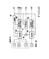
- Fig. 13 is a block diagram of the control circuit 1021 shown in Fig 12.
- the control circuit 1021 is substantially the same as the first embodiment of the control circuit 79 (Fig. 10), except that the control circuit 1021 receives the collision signal from the channel collision detector 1020 through a terminal 1021.
- a plurality of channels are formed along the time base.
- the present invention can also be applied to a plurality of channels formed with respect to the frequency bandwidth.
Landscapes
- Engineering & Computer Science (AREA)
- Computer Networks & Wireless Communication (AREA)
- Signal Processing (AREA)
- Physics & Mathematics (AREA)
- Astronomy & Astrophysics (AREA)
- Aviation & Aerospace Engineering (AREA)
- General Physics & Mathematics (AREA)
- Radio Relay Systems (AREA)
- Time-Division Multiplex Systems (AREA)
Applications Claiming Priority (6)
| Application Number | Priority Date | Filing Date | Title |
|---|---|---|---|
| JP57101913A JPS58219838A (ja) | 1982-06-14 | 1982-06-14 | マルチアクセス方式 |
| JP101913/82 | 1982-06-14 | ||
| JP58029741A JPS59154844A (ja) | 1983-02-24 | 1983-02-24 | パケツト通信装置 |
| JP29741/83 | 1983-02-24 | ||
| JP40057/83 | 1983-03-11 | ||
| JP58040057A JPS59167150A (ja) | 1983-03-11 | 1983-03-11 | パケツト通信装置 |
Publications (3)
| Publication Number | Publication Date |
|---|---|
| EP0097309A2 true EP0097309A2 (fr) | 1984-01-04 |
| EP0097309A3 EP0097309A3 (en) | 1985-05-22 |
| EP0097309B1 EP0097309B1 (fr) | 1987-11-11 |
Family
ID=27286704
Family Applications (1)
| Application Number | Title | Priority Date | Filing Date |
|---|---|---|---|
| EP83105809A Expired EP0097309B1 (fr) | 1982-06-14 | 1983-06-14 | Méthode et système d'accès multiple |
Country Status (4)
| Country | Link |
|---|---|
| US (1) | US4574378A (fr) |
| EP (1) | EP0097309B1 (fr) |
| CA (1) | CA1200933A (fr) |
| DE (1) | DE3374507D1 (fr) |
Cited By (4)
| Publication number | Priority date | Publication date | Assignee | Title |
|---|---|---|---|---|
| GB2310978B (en) * | 1994-12-20 | 2000-02-02 | 3Com Corp | Radio based collision detection for wireless communication system |
| US6847626B1 (en) | 1998-07-21 | 2005-01-25 | Tachyon, Inc. | Method and apparatus for multiple access in a communication system |
| US6982969B1 (en) | 1999-09-28 | 2006-01-03 | Tachyon, Inc. | Method and system for frequency spectrum resource allocation |
| US8451732B2 (en) | 2006-08-09 | 2013-05-28 | Denso Corporation | Inter-vehicle communication apparatus and method capable of detecting packet collision |
Families Citing this family (41)
| Publication number | Priority date | Publication date | Assignee | Title |
|---|---|---|---|---|
| JPS60239131A (ja) * | 1984-05-14 | 1985-11-28 | Nec Corp | Tdma衛星通信システムにおける状態情報伝送方式 |
| GB2165127B (en) * | 1984-09-26 | 1988-04-07 | Philips Electronic Associated | Multiple access communications system |
| US4665519A (en) * | 1985-11-04 | 1987-05-12 | Electronic Systems Technology, Inc. | Wireless computer modem |
| JPS62147822A (ja) * | 1985-12-23 | 1987-07-01 | Nec Corp | 時分割多元接続通信装置 |
| US5012469A (en) * | 1988-07-29 | 1991-04-30 | Karamvir Sardana | Adaptive hybrid multiple access protocols |
| JPH0817345B2 (ja) * | 1989-02-03 | 1996-02-21 | 日本電気株式会社 | 衛星通信方式 |
| CA2094710C (fr) * | 1990-10-23 | 1998-12-01 | Robert Clyde Dixon | Methode et appareil pour etablir des communications a etalement du spectre |
| US5917629A (en) * | 1990-10-29 | 1999-06-29 | International Business Machines Corporation | Transceiver for extending a CSMA/CD network for wireless communication |
| FR2669164B1 (fr) * | 1990-11-14 | 1993-02-05 | Thomson Csf | Procede de transmission de donnees entre mobiles ou vehicules autonomes. |
| JPH06284085A (ja) * | 1993-03-25 | 1994-10-07 | Toshiba Corp | ディジタル無線通信装置 |
| FR2708124B1 (fr) * | 1993-07-20 | 1995-09-01 | Thomson Csf | Procédé d'optimisation du débit d'un canal de communication en partage de temps. |
| US5581553A (en) * | 1993-08-18 | 1996-12-03 | Intervoice Limited Partnership | Distributed switching architecture |
| FI107575B (fi) * | 1994-06-20 | 2001-08-31 | Nokia Mobile Phones Ltd | Tiedonsiirtomenetelmä, tukiasema sekä tilaajapäätelaite |
| US5835711A (en) * | 1995-02-01 | 1998-11-10 | International Business Machines Corporation | Method and system for implementing multiple leaky bucket checkers using a hybrid synchronous/asynchronous update mechanism |
| US5812545A (en) * | 1996-01-04 | 1998-09-22 | Orion Atlantic, L.P. | Full mesh satellite-based multimedia networking system |
| DE69735476T2 (de) * | 1996-03-18 | 2006-10-19 | Koninklijke Philips Electronics N.V. | Nachrichten-kollisionsarbitrierung unter verwendung von mini-schlitzen |
| US5796726A (en) * | 1996-04-08 | 1998-08-18 | Ericsson Inc. | Systems and methods for random access in time division multiple access satellite radiotelephone communications |
| US5850392A (en) * | 1996-04-10 | 1998-12-15 | Ericsson Inc. | Spread spectrum random access systems and methods for time division multiple access radiotelephone communication systems |
| US5995805A (en) * | 1997-10-17 | 1999-11-30 | Lockheed Martin Missiles & Space | Decision-theoretic satellite communications system |
| US6006271A (en) * | 1998-02-27 | 1999-12-21 | 3Com Corporation | Method and protocol for complete collision avoidance contention resolution in local area networks |
| US6674730B1 (en) | 1998-08-04 | 2004-01-06 | Tachyon, Inc. | Method of and apparatus for time synchronization in a communication system |
| US6256483B1 (en) | 1998-10-28 | 2001-07-03 | Tachyon, Inc. | Method and apparatus for calibration of a wireless transmitter |
| US6411800B1 (en) | 1999-01-07 | 2002-06-25 | Surfernetwork.Com, Inc | Enhanced radio data system |
| US6735188B1 (en) | 1999-08-27 | 2004-05-11 | Tachyon, Inc. | Channel encoding and decoding method and apparatus |
| US6218896B1 (en) | 1999-08-27 | 2001-04-17 | Tachyon, Inc. | Vectored demodulation and frequency estimation apparatus and method |
| US6650636B1 (en) | 1999-08-27 | 2003-11-18 | Tachyon, Inc. | Transmission and reception of TCP/IP data over a wireless communication channel |
| US6532220B1 (en) | 1999-08-27 | 2003-03-11 | Tachyon, Inc. | System and method for efficient channel assignment |
| US6665292B1 (en) | 1999-08-27 | 2003-12-16 | Tachyon, Inc. | Transmission and reception of TCP/IP data over a wireless communication channel |
| US6674731B1 (en) | 1999-08-27 | 2004-01-06 | Tachyon, Inc. | Transmission and reception of TCP/IP data over a wireless communication channel |
| US20030193924A1 (en) * | 1999-09-10 | 2003-10-16 | Stephan Gehring | Medium access control protocol for centralized wireless network communication management |
| US20040090983A1 (en) * | 1999-09-10 | 2004-05-13 | Gehring Stephan W. | Apparatus and method for managing variable-sized data slots within a time division multiple access frame |
| US7023833B1 (en) | 1999-09-10 | 2006-04-04 | Pulse-Link, Inc. | Baseband wireless network for isochronous communication |
| US7088795B1 (en) * | 1999-11-03 | 2006-08-08 | Pulse-Link, Inc. | Ultra wide band base band receiver |
| US6970448B1 (en) | 2000-06-21 | 2005-11-29 | Pulse-Link, Inc. | Wireless TDMA system and method for network communications |
| US6952456B1 (en) | 2000-06-21 | 2005-10-04 | Pulse-Link, Inc. | Ultra wide band transmitter |
| US7313635B1 (en) * | 2002-03-21 | 2007-12-25 | Cisco Technology | Method and apparatus for simulating a load on an application server in a network |
| US20040228282A1 (en) * | 2003-05-16 | 2004-11-18 | Qi Bao | Method and apparatus for determining a quality measure of a channel within a communication system |
| US7639663B1 (en) | 2005-03-04 | 2009-12-29 | Itt Manufacturing Enterprises, Inc. | Method and apparatus for dynamic channel access within wireless networks |
| US7502360B2 (en) * | 2005-03-04 | 2009-03-10 | Itt Manufacturing Enterprises, Inc. | Method and apparatus for dynamic neighbor discovery within wireless networks using time division multiple access (TDMA) |
| US7768989B2 (en) * | 2005-03-04 | 2010-08-03 | Itt Manufacturing Enterprises, Inc. | Method and apparatus for multipoint voice operation in a wireless, Ad-Hoc environment |
| DE102009031839B4 (de) * | 2009-07-03 | 2011-06-09 | Ingmar Kruse | Verfahren zur Überwachung einzelner Photovoltaikmodule in einer Anordnung, die mehrere Photovoltaikmodule umfasst sowie eine Einrichtung zur Durchführung des vorgenannten Verfahrens |
Family Cites Families (8)
| Publication number | Priority date | Publication date | Assignee | Title |
|---|---|---|---|---|
| US4161786A (en) * | 1978-02-27 | 1979-07-17 | The Mitre Corporation | Digital bus communications system |
| US4210780A (en) * | 1978-03-27 | 1980-07-01 | The Mitre Corporation | Multiple access digital communications system |
| US4199662A (en) * | 1978-07-17 | 1980-04-22 | Lowe Charles S Jr | Hybrid control of time division multiplexing |
| US4281380A (en) * | 1978-12-27 | 1981-07-28 | Harris Corporation | Bus collision avoidance system for distributed network data processing communications system |
| US4409592A (en) * | 1981-04-20 | 1983-10-11 | Hunt V Bruce | Multipoint packet data communication system using random access and collision detection techniques |
| US4439763A (en) * | 1981-09-03 | 1984-03-27 | Bell Telephone Laboratories, Incorporated | Collision avoiding system and protocol for a multiple access digital communications system |
| US4439856A (en) * | 1982-02-24 | 1984-03-27 | General Electric Company | Bimodal bus accessing system |
| US4464749A (en) * | 1982-02-24 | 1984-08-07 | General Electric Company | Bi-directional token flow system |
-
1983
- 1983-06-10 US US06/503,264 patent/US4574378A/en not_active Expired - Lifetime
- 1983-06-14 EP EP83105809A patent/EP0097309B1/fr not_active Expired
- 1983-06-14 DE DE8383105809T patent/DE3374507D1/de not_active Expired
- 1983-06-14 CA CA000430342A patent/CA1200933A/fr not_active Expired
Non-Patent Citations (3)
| Title |
|---|
| AFIPS Conference Proceedings 1975 National Computer Conference May 19-22, 1975 Anaheim, California AFIPS Press, Montvale, New Jersey (US). pages 143-153. S.S. LAM et al.: "Dynamic Control Schemes for a Packet Switched Multiaccess Broadcast Channel". * |
| IEEE fifth International Conference on Digital Satellite Communications March 2 3-26, 1981, Genoa, (IT) New York, (US). pages 397-401. G.D. DILL: "Low-Cost TDMA for the Intelsat System". * |
| IEEE Transactions on Communications Vol. COM-23, No. 4, April 1975 New York, (US). pages 410-423 L. KLEINROCK et al.: "Packet Switching in a Multiaccess Broadcast Channel: Performance Evaluation". * |
Cited By (5)
| Publication number | Priority date | Publication date | Assignee | Title |
|---|---|---|---|---|
| GB2310978B (en) * | 1994-12-20 | 2000-02-02 | 3Com Corp | Radio based collision detection for wireless communication system |
| US6847626B1 (en) | 1998-07-21 | 2005-01-25 | Tachyon, Inc. | Method and apparatus for multiple access in a communication system |
| US7203204B2 (en) | 1998-07-21 | 2007-04-10 | Tachyon Networks Incorporated | Method and apparatus for multiple access in a communication system |
| US6982969B1 (en) | 1999-09-28 | 2006-01-03 | Tachyon, Inc. | Method and system for frequency spectrum resource allocation |
| US8451732B2 (en) | 2006-08-09 | 2013-05-28 | Denso Corporation | Inter-vehicle communication apparatus and method capable of detecting packet collision |
Also Published As
| Publication number | Publication date |
|---|---|
| CA1200933A (fr) | 1986-02-18 |
| EP0097309A3 (en) | 1985-05-22 |
| DE3374507D1 (en) | 1987-12-17 |
| US4574378A (en) | 1986-03-04 |
| EP0097309B1 (fr) | 1987-11-11 |
Similar Documents
| Publication | Publication Date | Title |
|---|---|---|
| EP0097309B1 (fr) | Méthode et système d'accès multiple | |
| US6347236B1 (en) | Remote wireless unit having reduced power operating mode for a discrete multitone spread spectrum communications system | |
| US5394433A (en) | Frequency hopping pattern assignment and control in multiple autonomous collocated radio networks | |
| EP0680159B1 (fr) | Procédé et dispositif de commande de la puissance de transmission pour différents types de dispositifs sans fil dans un système AMDC | |
| US5805586A (en) | Method, device and data communication system for multilink polling | |
| DE60126121T2 (de) | Übertragungs-ablaufsteuerung für ein zellulares drahtloses netzwerk mit mehreren antennen | |
| US6236662B1 (en) | Multirate time reservation multi-access protocol | |
| Gitman | On the capacity of slotted ALOHA networks and some design problems | |
| GB2069799A (en) | Method for the transmission of data packets | |
| CN1060899C (zh) | 通信系统信道有效优化通过量和延迟最小化的方法和系统 | |
| CN1084120C (zh) | 实现无线通信信道时间共享的装置 | |
| US20050054288A1 (en) | Method for dynamic load management of random access shared communications channels | |
| US6728257B1 (en) | Fluid flow fair scheduling emulation in wireless shared channel packet communication network | |
| EP1021893B1 (fr) | Commutation par paquets dans un systeme de radiocommunication cellulaire | |
| US20020183067A1 (en) | Method and system for wirelessly transmitting data between a base transceiver station and a subscriber unit | |
| US20050180377A1 (en) | Radio communication system time slot allocation method | |
| WO1998035473A2 (fr) | Unite sans fil a distance presentant un mode de fonctionnement a courant limite | |
| Lam | Multiple access protocols | |
| Raychaudhuri | Selective reject ALOHA/FCFS: an advanced VSAT channel access protocol | |
| EP1082665A1 (fr) | Estimation de trafic offert et applications permettant de l'utiliser dans un reseau de communication | |
| JP2621776B2 (ja) | パケット衛星通信方式 | |
| Al‐Mosawi et al. | Rain granularity effects on bandwidth demand for faded DVB‐RCS systems | |
| WO1998037653A2 (fr) | Unite eloignee sans fil a mode de fonctionnement avec consommation electrique reduite pour systeme de telecommunications multivoies discret a spectre disperse | |
| Courtois et al. | Channel-access protocols and routing strategies for mobile packet radio networks | |
| Celandroni et al. | FEEDERS-TDMA |
Legal Events
| Date | Code | Title | Description |
|---|---|---|---|
| PUAI | Public reference made under article 153(3) epc to a published international application that has entered the european phase |
Free format text: ORIGINAL CODE: 0009012 |
|
| AK | Designated contracting states |
Designated state(s): DE FR GB IT NL |
|
| 17P | Request for examination filed |
Effective date: 19840418 |
|
| PUAL | Search report despatched |
Free format text: ORIGINAL CODE: 0009013 |
|
| AK | Designated contracting states |
Designated state(s): DE FR GB IT NL |
|
| 17Q | First examination report despatched |
Effective date: 19860502 |
|
| GRAA | (expected) grant |
Free format text: ORIGINAL CODE: 0009210 |
|
| AK | Designated contracting states |
Kind code of ref document: B1 Designated state(s): DE FR GB IT NL |
|
| REF | Corresponds to: |
Ref document number: 3374507 Country of ref document: DE Date of ref document: 19871217 |
|
| ET | Fr: translation filed | ||
| ITF | It: translation for a ep patent filed | ||
| PLBE | No opposition filed within time limit |
Free format text: ORIGINAL CODE: 0009261 |
|
| STAA | Information on the status of an ep patent application or granted ep patent |
Free format text: STATUS: NO OPPOSITION FILED WITHIN TIME LIMIT |
|
| 26N | No opposition filed | ||
| PGFP | Annual fee paid to national office [announced via postgrant information from national office to epo] |
Ref country code: GB Payment date: 19910603 Year of fee payment: 9 |
|
| PGFP | Annual fee paid to national office [announced via postgrant information from national office to epo] |
Ref country code: FR Payment date: 19910621 Year of fee payment: 9 |
|
| ITTA | It: last paid annual fee | ||
| PGFP | Annual fee paid to national office [announced via postgrant information from national office to epo] |
Ref country code: NL Payment date: 19910630 Year of fee payment: 9 |
|
| PGFP | Annual fee paid to national office [announced via postgrant information from national office to epo] |
Ref country code: DE Payment date: 19910803 Year of fee payment: 9 |
|
| PG25 | Lapsed in a contracting state [announced via postgrant information from national office to epo] |
Ref country code: GB Effective date: 19920614 |
|
| PG25 | Lapsed in a contracting state [announced via postgrant information from national office to epo] |
Ref country code: NL Effective date: 19930101 |
|
| GBPC | Gb: european patent ceased through non-payment of renewal fee |
Effective date: 19920614 |
|
| NLV4 | Nl: lapsed or anulled due to non-payment of the annual fee | ||
| PG25 | Lapsed in a contracting state [announced via postgrant information from national office to epo] |
Ref country code: FR Effective date: 19930226 |
|
| PG25 | Lapsed in a contracting state [announced via postgrant information from national office to epo] |
Ref country code: DE Effective date: 19930302 |
|
| REG | Reference to a national code |
Ref country code: FR Ref legal event code: ST |