EP0097315A2 - Dispositif de brûleur à fuel pour fourneaux roulants - Google Patents
Dispositif de brûleur à fuel pour fourneaux roulants Download PDFInfo
- Publication number
- EP0097315A2 EP0097315A2 EP83105830A EP83105830A EP0097315A2 EP 0097315 A2 EP0097315 A2 EP 0097315A2 EP 83105830 A EP83105830 A EP 83105830A EP 83105830 A EP83105830 A EP 83105830A EP 0097315 A2 EP0097315 A2 EP 0097315A2
- Authority
- EP
- European Patent Office
- Prior art keywords
- fuel
- nozzle
- evaporator
- burner
- fuel supply
- Prior art date
- Legal status (The legal status is an assumption and is not a legal conclusion. Google has not performed a legal analysis and makes no representation as to the accuracy of the status listed.)
- Granted
Links
Images


Classifications
-
- F—MECHANICAL ENGINEERING; LIGHTING; HEATING; WEAPONS; BLASTING
- F23—COMBUSTION APPARATUS; COMBUSTION PROCESSES
- F23K—FEEDING FUEL TO COMBUSTION APPARATUS
- F23K5/00—Feeding or distributing other fuel to combustion apparatus
- F23K5/02—Liquid fuel
- F23K5/14—Details thereof
- F23K5/147—Valves
-
- F—MECHANICAL ENGINEERING; LIGHTING; HEATING; WEAPONS; BLASTING
- F23—COMBUSTION APPARATUS; COMBUSTION PROCESSES
- F23D—BURNERS
- F23D11/00—Burners using a direct spraying action of liquid droplets or vaporised liquid into the combustion space
- F23D11/36—Details
- F23D11/44—Preheating devices; Vaporising devices
- F23D11/441—Vaporising devices incorporated with burners
- F23D11/443—Vaporising devices incorporated with burners heated by the main burner flame
-
- F—MECHANICAL ENGINEERING; LIGHTING; HEATING; WEAPONS; BLASTING
- F23—COMBUSTION APPARATUS; COMBUSTION PROCESSES
- F23D—BURNERS
- F23D11/00—Burners using a direct spraying action of liquid droplets or vaporised liquid into the combustion space
- F23D11/36—Details
- F23D11/42—Starting devices
-
- F—MECHANICAL ENGINEERING; LIGHTING; HEATING; WEAPONS; BLASTING
- F24—HEATING; RANGES; VENTILATING
- F24C—DOMESTIC STOVES OR RANGES ; DETAILS OF DOMESTIC STOVES OR RANGES, OF GENERAL APPLICATION
- F24C5/00—Stoves or ranges for liquid fuels
- F24C5/02—Stoves or ranges for liquid fuels with evaporation burners, e.g. dish type
-
- F—MECHANICAL ENGINEERING; LIGHTING; HEATING; WEAPONS; BLASTING
- F24—HEATING; RANGES; VENTILATING
- F24C—DOMESTIC STOVES OR RANGES ; DETAILS OF DOMESTIC STOVES OR RANGES, OF GENERAL APPLICATION
- F24C5/00—Stoves or ranges for liquid fuels
- F24C5/20—Stoves or ranges for liquid fuels with special adaptation for travelling, e.g. collapsible
Definitions
- the invention relates to an oil burner arrangement for field cookers with a fuel container, with a fuel supply supplying the fuel to a burner nozzle and with an evaporator which is arranged in the fuel supply and heated by the burner, a spray nozzle bringing the oil in the form of an oil mist being arranged at the inlet end of the evaporator.
- An oil burner arrangement of the type mentioned is known (DE-OS 31 18 644), in which the evaporator must be heated from an open shell before the burner is operated. With such a burner arrangement, practically residue-free combustion of the fuel, preferably diesel oil, can be achieved.
- the burner arrangement achieves excellent fire performance values, such as a high CO 2 content in the fuel gases of, for example, 13% and a soot number 0.
- the structure of the burner arrangement means that the gasified fuel tends to have an intermittent pressure behavior. This pressure behavior may be increased if the pressure build-up temporarily prevents the inflow of fuel. For this reason, it is expedient to use a throttle in the fuel feed line immediately before the evaporator. This throttle acts on the one hand as an attenuator and on the other hand as a flow limiter.
- a throttle in the form of a nozzle a nozzle bore with a very small inner diameter (e.g. 0.25 mm) is required. It is difficult to make such a hole. There is also a risk of constipation. In the cleaning work required as a result, the bore diameter is inevitably increased, so that the damping behavior and the flow rate change.
- a complex filter must be installed upstream of this nozzle in practice.
- the present invention consists in that an oil burner arrangement of the type mentioned at the outset, in which the evaporator is also associated with a starter mixing nozzle which heats it up at the start of operation and is connected to an air supply and a fuel supply.
- This starter mixing nozzle preferably consists of a burner nozzle, a fuel chamber arranged in front of the inlet to the burner nozzle, an air nozzle arranged centrally to the burner nozzle and opening into the fuel chamber, and a perforated burner tube surrounding the burner nozzle.
- This starter mixing nozzle can be easily ignited with a lighter or a match or with the help of a fuse, and it achieves a stable, powerful flame that can heat the evaporator to a temperature of over 360 ° C within a short time (3 - 4 minutes) .
- a central distributor control valve which controls the air supply and the fuel supply to the starter mixing nozzle is expediently provided.
- the evaporator is expediently provided with a double jacket which forms a jacket cavity surrounding the evaporator chamber, a heating tube which is connected to this and which is acted upon by the flame of the main nozzle and which is filled with an evaporable liquid being arranged at the lowest point of the jacket cavity.
- the vaporizable liquid can be water.
- the evaporator is expediently arranged so that the condensing liquid runs back into the heating tube.
- the jacket cavity is preferably evacuated.
- the distributor control valve according to the invention achieves an efficient oil burner arrangement for field cookers which can be put into operation easily.
- the special design of the evaporator results in a largely uniform temperature over the entire evaporator surface.
- the invention is further seen in the fact that the supply line to the evaporator and / or the fuel supply line to the starter mixing nozzle as a capillary tube with an inner diameter of 0.6-0.8 mm, preferably 0.8 mm, and with the fuel admission pressure and the volume flow of the fuel adapted length trained.
- a filter is not required due to the arrangement according to the invention.
- the volume flow can be set exactly through the length of the capillary tube. This volume flow then remains unchanged at a given pressure difference.
- the arrangement requires very little technical effort, and it enables very simple assembly.
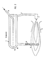
- the combustion chamber of a field cooker is designated 1.
- 2 is the main burner nozzle
- 6 is a venturi tube which is penetrated by the flame of the main burner nozzle.
- Above the burner 5 is the evaporator 2, which is heated by the flame of the main burner nozzle during operation.
- the evaporator 2 receives fuel from a fuel tank 14 via a fuel line 16, a central distributor control valve 8 and a further fuel line 20 fed. This fuel is evaporated in the evaporator 2, and this fuel vapor is supplied to the main burner nozzle 5.
- 10 is an air tank with a pressure limiter 11 with a pressure indicator.
- 12 is a pressure reducing valve with pressure indicator for the fuel tank. The fuel is conveyed from the fuel tank 14 into the evaporator 2 or into the starter mixing nozzle by this compressed air.
- 13 is a pressure reducing valve with a pressure indicator for the starter mixing nozzle 7, which fuel is supplied via the fuel lines 16 and 19 and via the central distributor control valve 8 and air via the lines 17 and 18 and also via the distributor control valve 8.
- Fig. 2 shows a special design of the evaporator 2, which is provided here with a double jacket, which surrounds the actual evaporator chamber 2a and forms a jacket cavity 2b, at the lowest point of which a heating tube 2c is connected, which is filled with an evaporable liquid 2d, for example Water is filled.
- the heating tube 2c is guided to the area of the heating flame of the main burner nozzle 5. Its cavity forms a closed system with the jacket cavity 2b of the evaporator.
- the water 2d evaporates, the temperature in the system is uniform at constant pressure.
- the heat transport is - as long as there is still liquid in the heating tube 2c - very intensive because the high condensate heat is given off to the colder parts of the system when the steam condenses.
- the system must be designed so that the condensate that forms can flow back down into the heating pipe 2c.
- the heat transfer stops i.e. the system is balanced and there are neither overheated nor too cold spots in the evaporator. If the heating pipe 2c is heated even further, it does get a higher temperature, but the evaporator does not, because heat is no longer transported.
- the system must be designed so that the temperature of approx. 400 ° C is reached with a minimum output. This largely eliminates the dreaded cracking of diesel oil or kerosene.
- Fig. 3 shows the starter mixing nozzle on a larger scale.
- 30 is a burner body with an air connection 35 for the air line 18, from which an air supply 33 leads to an air nozzle 34.
- 36 is a fuel connection for the fuel line 19.
- This fuel connection 36 is connected via a fuel supply bore 37 to a fuel chamber 38 which is directly adjacent to a burner nozzle 39a in a nozzle nut 39.
- the air nozzle 34 borders - opposite the fuel nozzle 39a - the fuel chamber.
- This fuel mist to which additional combustion air is fed through the air holes 32 in the burner tube 31, can easily be ignited with the aid of a match, a lighter, a fuse or the like.
- the flame that is produced is stable and powerful enough to heat the evaporator 2 to a temperature of over 360 ° C. in a relatively short time (3-4 minutes).
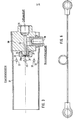
- Fig. 4 shows the central manifold control valve 8 in one Intersection.
- the valve consists of a fixed base 22 with bores and control slots, a rotatable control disc 23 with a shaft 23a to which an operating lever 9 is attached, an upper part 24 and a spring 25 which urges the rotatable disc 23 against the base 22.
- the bores or control slots in the base 22 are shown with solid lines, while the bores and control slots in the rotatable control disk 23 are shown in dashed lines.
- fuel is via the control channel 27 defined in its width and milled in the rotatable control disk 23 - shown in dashed lines - in position I bore 28 for the starter mixing nozzle 7, in the positions II and III until shortly before the position IV in the control channel 29, which is incorporated in the base 22, passed via the fuel line 20 into the evaporator 2.
- control channel 27 connects the air inlet bore 30 with the control channel 29 and the fuel inlet bore 26.
- the second control channel 31 milled in the rotatable control disk 23 connects the air inlet bore 30 to the air outlet bore 32 in position I and releases air for the starter mixing nozzle 7.
- the control channel 31 connects the air inlet port 30 with the air outlet hole 32 and with the bore 28 and thus promotes the air g 19 located in the starting fuel-mixing nozzle 7 and do in the LEI.
- control channel 31 no longer has any influence.
- valve 8 is turned to position II.
- the air lines 17 and 18 remain connected to one another, i.e. air is still applied to the starter mixing nozzle 7.
- the air line 17 is connected to the fuel line 19 at the same time, so that the starter mixing nozzle is supplied with fuel (approx. 20 seconds) until the fuel line and starter mixing nozzle are blown empty and cleaned of fuel residues.
- the fuel lines 16 and 20 are also connected to one another, so that fuel immediately enters the preheated evaporator at the time of the switchover and evaporates there.
- the fuel vapor reaches the main nozzle 5 directly via the steam line 21.
- the fuel steam jet emerging from this main nozzle conveys the necessary combustion air via the venturi tube 6, mixes with it and ignites on the still burning flame of the starter mixing nozzle.
- the maximum power is not supplied to the evaporator in position II because the combustion chamber would be overloaded at the moment when the main flame was full, which would result in a brief formation of soot and smoke.
- the central distributor control valve 8 is designed in such a way that the position of the burner can be regulated continuously from position c "full load” to shortly before position b "minimum load". Only the fuel lines 16 and 20 are connected to one another over the entire control range.
- the fuel line 20 (FIG. 1) is designed as a capillary tube with an inner diameter of 0.6-0.8 mm, preferably 0.8 mm, the length of the capillary tube 30 being adapted to the fuel pressure and the required volume volume of the fuel .
- a capillary tube is shown in Fig. 2.
- the inlet end is designated with 31 and the outlet end with 32.
- the fuel feed line 21 (FIG. 1) to the starter mixing nozzle 5 can also be designed as a capillary tube with an inner diameter of 0.6-0.8 mm, preferably 0.8 mm, likewise the Length of the capillary tube is adapted to the fuel pressure and the desired volume flow of the fuel.
Landscapes
- Engineering & Computer Science (AREA)
- Chemical & Material Sciences (AREA)
- Combustion & Propulsion (AREA)
- Mechanical Engineering (AREA)
- General Engineering & Computer Science (AREA)
- Spray-Type Burners (AREA)
Priority Applications (1)
| Application Number | Priority Date | Filing Date | Title |
|---|---|---|---|
| AT83105830T ATE26013T1 (de) | 1982-06-21 | 1983-06-14 | Oelbrenneranordnung fuer feldkochherde. |
Applications Claiming Priority (4)
| Application Number | Priority Date | Filing Date | Title |
|---|---|---|---|
| DE3223108A DE3223108C2 (de) | 1982-06-21 | 1982-06-21 | Verdampfungsölbrenner |
| DE3223108 | 1982-06-21 | ||
| DE3238722A DE3238722C2 (de) | 1982-10-19 | 1982-10-19 | Verdampfungsölbrenner für Feldkochherde |
| DE3238722 | 1982-10-19 |
Publications (3)
| Publication Number | Publication Date |
|---|---|
| EP0097315A2 true EP0097315A2 (fr) | 1984-01-04 |
| EP0097315A3 EP0097315A3 (en) | 1984-05-16 |
| EP0097315B1 EP0097315B1 (fr) | 1987-03-18 |
Family
ID=25802536
Family Applications (1)
| Application Number | Title | Priority Date | Filing Date |
|---|---|---|---|
| EP83105830A Expired EP0097315B1 (fr) | 1982-06-21 | 1983-06-14 | Dispositif de brûleur à fuel pour fourneaux roulants |
Country Status (2)
| Country | Link |
|---|---|
| EP (1) | EP0097315B1 (fr) |
| SG (1) | SG75288G (fr) |
Cited By (4)
| Publication number | Priority date | Publication date | Assignee | Title |
|---|---|---|---|---|
| EP0413214A3 (en) * | 1989-08-17 | 1991-05-15 | Alfred Kaercher Gmbh & Co. | Pressurized vaporising burner, particularly for field ranges |
| EP0612941A1 (fr) * | 1993-02-26 | 1994-08-31 | A.M. DI VANINI GIUSEPPE & C. S.n.c. | Robinet à disque pour régler l'écoulement de gaz |
| DE10360009A1 (de) * | 2003-12-19 | 2005-07-28 | J. Eberspächer GmbH & Co. KG | Brennstoffzuführleitungssystem bei einem Heizgerät, insbesondere Fahrzeugheizgerät |
| DE102006034479B4 (de) * | 2006-07-26 | 2010-08-19 | Holger Dr. Meyer | Verfahren zur Verdampfung und Verbrennung von Flüssigbrennstoff |
Family Cites Families (2)
| Publication number | Priority date | Publication date | Assignee | Title |
|---|---|---|---|---|
| GB715578A (en) * | 1951-08-09 | 1954-09-15 | Heizmotoren Ges Mit Beschraenk | Improvements in or relating to heating apparatus incorporating a reso-jet tube |
| DE3118644C2 (de) * | 1981-05-11 | 1985-05-02 | Progress-Werk Oberkirch Ag, 7602 Oberkirch | Verdampfungsölbrenner für Feldkochherde |
-
1983
- 1983-06-14 EP EP83105830A patent/EP0097315B1/fr not_active Expired
-
1988
- 1988-11-02 SG SG752/88A patent/SG75288G/en unknown
Cited By (5)
| Publication number | Priority date | Publication date | Assignee | Title |
|---|---|---|---|---|
| EP0413214A3 (en) * | 1989-08-17 | 1991-05-15 | Alfred Kaercher Gmbh & Co. | Pressurized vaporising burner, particularly for field ranges |
| EP0612941A1 (fr) * | 1993-02-26 | 1994-08-31 | A.M. DI VANINI GIUSEPPE & C. S.n.c. | Robinet à disque pour régler l'écoulement de gaz |
| DE10360009A1 (de) * | 2003-12-19 | 2005-07-28 | J. Eberspächer GmbH & Co. KG | Brennstoffzuführleitungssystem bei einem Heizgerät, insbesondere Fahrzeugheizgerät |
| EP1544543A3 (fr) * | 2003-12-19 | 2008-12-31 | J. Eberspächer GmbH & Co. KG | Système de conduite d'alimentation en carburant pour un dispositif de chauffage, en particulier dispositif de chauffage pour voiture |
| DE102006034479B4 (de) * | 2006-07-26 | 2010-08-19 | Holger Dr. Meyer | Verfahren zur Verdampfung und Verbrennung von Flüssigbrennstoff |
Also Published As
| Publication number | Publication date |
|---|---|
| EP0097315B1 (fr) | 1987-03-18 |
| SG75288G (en) | 1991-01-04 |
| EP0097315A3 (en) | 1984-05-16 |
Similar Documents
| Publication | Publication Date | Title |
|---|---|---|
| DE2539993C2 (de) | Brenner für flüssigen oder gasförmigen Brennstoff | |
| DE3036841C2 (de) | Verdampfungsbrenner für flüssigen Brennstoff, insbesondere Kerosin | |
| DE2700671C2 (de) | Blaubrennender Ölbrenner | |
| DE3010078C2 (de) | Mit flüssigem Brennstoff betriebener Brenner für Heizvorrichtungen | |
| DE2060158B2 (de) | Brennstoffeinspritzvorrichtung für ein Gasturbinenstrahltriebwerk | |
| EP0843083B1 (fr) | Préevaporateur de combustible | |
| DE4032582C2 (de) | Gasbrenner, insbesondere für Glasschmelzöfen | |
| EP0283435B1 (fr) | Brûleur | |
| EP0097315B1 (fr) | Dispositif de brûleur à fuel pour fourneaux roulants | |
| DE3223108C2 (de) | Verdampfungsölbrenner | |
| DE3122770C2 (de) | Einrichtung zur Erzeugung eines Brennstoff-Luft-Gemisches durch Verdunsten von Brennstoff in vorgewärmte Verbrennungsluft | |
| DE3743205A1 (de) | Brenneinrichtung | |
| DE19822336C2 (de) | Vorrichtung zum Betreiben eines atmosphärischen, insbesondere vollvormischenden Gasbrenners | |
| DE3238722C2 (de) | Verdampfungsölbrenner für Feldkochherde | |
| EP0445393B1 (fr) | Brûleur avec récirculation des gaz d'échappement, notamment brûleur à air soufflé | |
| DE2453469A1 (de) | Verdampferoelbrenner | |
| DE2924012C2 (de) | Flüssiggasbrenner | |
| EP1664630A1 (fr) | Bruleur pour du combustible liquide | |
| DE2748743C2 (de) | Gasheizgerät | |
| DE3043698A1 (de) | Doppelbrennstoffsystem fuer gasturbinentriebwerke | |
| AT141343B (de) | Brenner für schwerflüssige Brennstoffe. | |
| DE695735C (de) | Benzinbrenner | |
| DE19810750A1 (de) | Verfahren und Vorrichtung zum Betreiben eines atmosphärischen Gasbrenners | |
| DE3148172A1 (de) | "druckverdampferbrenner" | |
| AT397565B (de) | Gasdüse |
Legal Events
| Date | Code | Title | Description |
|---|---|---|---|
| PUAI | Public reference made under article 153(3) epc to a published international application that has entered the european phase |
Free format text: ORIGINAL CODE: 0009012 |
|
| AK | Designated contracting states |
Designated state(s): AT BE CH FR GB IT LI NL |
|
| PUAL | Search report despatched |
Free format text: ORIGINAL CODE: 0009013 |
|
| AK | Designated contracting states |
Designated state(s): AT BE CH FR GB IT LI NL |
|
| RHK1 | Main classification (correction) |
Ipc: F23D 11/44 |
|
| 17P | Request for examination filed |
Effective date: 19841106 |
|
| ITF | It: translation for a ep patent filed | ||
| GRAA | (expected) grant |
Free format text: ORIGINAL CODE: 0009210 |
|
| AK | Designated contracting states |
Kind code of ref document: B1 Designated state(s): AT BE CH FR GB IT LI NL |
|
| REF | Corresponds to: |
Ref document number: 26013 Country of ref document: AT Date of ref document: 19870415 Kind code of ref document: T |
|
| ET | Fr: translation filed | ||
| PLBE | No opposition filed within time limit |
Free format text: ORIGINAL CODE: 0009261 |
|
| STAA | Information on the status of an ep patent application or granted ep patent |
Free format text: STATUS: NO OPPOSITION FILED WITHIN TIME LIMIT |
|
| 26N | No opposition filed | ||
| PGFP | Annual fee paid to national office [announced via postgrant information from national office to epo] |
Ref country code: GB Payment date: 19900522 Year of fee payment: 8 |
|
| PGFP | Annual fee paid to national office [announced via postgrant information from national office to epo] |
Ref country code: CH Payment date: 19900523 Year of fee payment: 8 |
|
| PGFP | Annual fee paid to national office [announced via postgrant information from national office to epo] |
Ref country code: BE Payment date: 19900531 Year of fee payment: 8 |
|
| PGFP | Annual fee paid to national office [announced via postgrant information from national office to epo] |
Ref country code: FR Payment date: 19900629 Year of fee payment: 8 Ref country code: AT Payment date: 19900629 Year of fee payment: 8 |
|
| ITTA | It: last paid annual fee | ||
| PGFP | Annual fee paid to national office [announced via postgrant information from national office to epo] |
Ref country code: NL Payment date: 19900630 Year of fee payment: 8 |
|
| PG25 | Lapsed in a contracting state [announced via postgrant information from national office to epo] |
Ref country code: GB Effective date: 19910614 Ref country code: AT Effective date: 19910614 |
|
| PG25 | Lapsed in a contracting state [announced via postgrant information from national office to epo] |
Ref country code: LI Effective date: 19910630 Ref country code: CH Effective date: 19910630 Ref country code: BE Effective date: 19910630 |
|
| BERE | Be: lapsed |
Owner name: PROGRESS-WERK OBERKIRCH A.G. Effective date: 19910630 |
|
| PG25 | Lapsed in a contracting state [announced via postgrant information from national office to epo] |
Ref country code: NL Effective date: 19920101 |
|
| GBPC | Gb: european patent ceased through non-payment of renewal fee | ||
| NLV4 | Nl: lapsed or anulled due to non-payment of the annual fee | ||
| PG25 | Lapsed in a contracting state [announced via postgrant information from national office to epo] |
Ref country code: FR Effective date: 19920228 |
|
| REG | Reference to a national code |
Ref country code: CH Ref legal event code: PL |