EP0097324A2 - Clamping assembly for heat exchanger tube plates - Google Patents
Clamping assembly for heat exchanger tube plates Download PDFInfo
- Publication number
- EP0097324A2 EP0097324A2 EP83105860A EP83105860A EP0097324A2 EP 0097324 A2 EP0097324 A2 EP 0097324A2 EP 83105860 A EP83105860 A EP 83105860A EP 83105860 A EP83105860 A EP 83105860A EP 0097324 A2 EP0097324 A2 EP 0097324A2
- Authority
- EP
- European Patent Office
- Prior art keywords
- tube plate
- segments
- ring
- circumferential
- segmented ring
- Prior art date
- Legal status (The legal status is an assumption and is not a legal conclusion. Google has not performed a legal analysis and makes no representation as to the accuracy of the status listed.)
- Granted
Links
Images


Classifications
-
- F—MECHANICAL ENGINEERING; LIGHTING; HEATING; WEAPONS; BLASTING
- F28—HEAT EXCHANGE IN GENERAL
- F28F—DETAILS OF HEAT-EXCHANGE AND HEAT-TRANSFER APPARATUS, OF GENERAL APPLICATION
- F28F9/00—Casings; Header boxes; Auxiliary supports for elements; Auxiliary members within casings
- F28F9/02—Header boxes; End plates
- F28F9/0219—Arrangements for sealing end plates into casing or header box; Header box sub-elements
-
- F—MECHANICAL ENGINEERING; LIGHTING; HEATING; WEAPONS; BLASTING
- F28—HEAT EXCHANGE IN GENERAL
- F28F—DETAILS OF HEAT-EXCHANGE AND HEAT-TRANSFER APPARATUS, OF GENERAL APPLICATION
- F28F2275/00—Fastening; Joining
- F28F2275/08—Fastening; Joining by clamping or clipping
- F28F2275/085—Fastening; Joining by clamping or clipping with snap connection
Definitions
- This invention relates to an assembly for clamping tube plates in heat exchangers.
- the technical field of heat exchangers is known to comprise a large variety-of designs wherein a tube plate is arranged to bear, with the interposition of a gasket, on a surface suitably formed on the shell end, and is clamped in that position to sealingly separate the fluid flown through the tube interiors and the fluid which sweeps the tube exteriors in flowing through the space portion enclosed by the shen.
- the devices for clamping the tube plate are quite numerous in the art, such as, to name but a few, a device which includes a plurality of stud bolts arranged around the gasket and adapted to be engaged with holes provided in the tube plate which is tightened down by means of nuts, or the one including a ring which is inserted into a peripheral groove of the tube plate, wherewith braces are associated which engage with a second ring overlying the peripheral area of said tube plate so as to compress it onto said gasket by tightening nuts provided at the brace ends.
- the ring For its insertion into the circumferential groove, the ring is fabricated in plural segments which, of course, must be held in place, and this problem is solved, in the cited device,through the use of a unitary construction retaining ring which is inserted within the segmented ring on the opposite side to that facing the tube plate.
- the task of this invention is to provide an improved device for clamping tube plates in heat exchangers, which affords the possibility of maximizing the diameter of the circumference containing the centers of the tube plate holes relating to the outermost tubes in the tube nest, thereby providing savings which, in view of the dimensions involved, may be of determining importance to the exchanger economy.
- Yet another object of this invention is to provide a clamping device, wherein the divider diaphragm, as required with exchangers having a number of passageways at the tube side which is a multiple of two, such as those comprising U-like tubes, can be fabricated in a simpler manner.
- a clamping assembly for tube plates in heat exchangers comprising a ring made up of a number of segments and effective to be inserted into a circumferential groove formed in the exchanger header chamber portion and having, in the radial direction, such dimensions as to include, in the reach of the annular portion thereof projecting beyond said groove, means effective to press against the peripheral area of the tube plate, bearing with the interposition of a sealing gasket, on a surface of said header portion, characterized in that it comprises within the header chamber a circumferential formation adapted to be associated, above said tube plate, with the inside diameter periphery of said segmented ring.
- said circumferential member is formed by a lug formation on the tube plate, and may also be formed by alug formation on a plate connected to one end of a circumferential sleeve which is in contact with said tube plate with its other end.
- header chamber portion of the exchanger indicated at 1 is the header chamber portion of the exchanger, and at 2 the tube plate which is to be secured relatively to said header portion with the interposition of a gasket 3 which provides a seal at the area enclosed by the shell 4 for the fluid contained therein.
- a circumferential groove 5 is formed, wherein there is inserted, in accordance with a prior technique developed by this Applicant, a ring 6, which is fabricated, for fitting it in place, from a number of segments.
- the ring 6 carries, at the annular portion projecting beyond the groove 5, means effective to press the plate 2 against the gasket 3 , which means comprise, also according to developments by this same Applicant, a plurality of small cylinders 7 guided in equally spaced holes extending substantially parallel to the longitudinal axis of the exchanger, each of them being urged with one end against the tube plate 2 by the action of a screw 8.
- the segments which make up the ring 6 are held in place by the circumferential member comprising the lug 2a on the tube plate 2, associated at the inside diameter of said ring 6, and finally, indicated at 9 is a second segmented ring, also inserted into the groove 5, which enables the segments of the ring 6 to be fitted and disassembled, and also transfers the force developed by the pressing means 7,8 cooperating with said ring 6 to the crown or ceiling of said groove 5.
- Figures 2 and 3 illustrate a first modified embodiment of the invention; indicated at 6 therein is again the segmented ring which is inserted into the circumferential groove 5 and comprises a plurality of segments, such as 6a,6b,6c,6d,6e, which include small cylinders 7 urged by screws 8 inserted through threaded holes, such as 8a and 8b, in the segment 6d.
- segmented ring which is inserted into the circumferential groove 5 and comprises a plurality of segments, such as 6a,6b,6c,6d,6e, which include small cylinders 7 urged by screws 8 inserted through threaded holes, such as 8a and 8b, in the segment 6d.
- the assembling sequence of the segments provides for the initial positioning of the segments in the arc extending between the segment 6c and segment 6d, these latter being excluded, and of the segments in the diametrically opposite arc, all segments being matingly limited by radial end surfaces; then, there are assembled the segments 6c and 6d and their symmetrical counterparts with respect to the diametrical plane 12, which are bordered by a radial surface and a surface parallel to said plane 12, and finally the segments 6a and 6b are inserted which have both their end surfaces parallel to the plane 12, without encountering interference problems.
- the segments with their end surfaces parallel to the diametrical plane may differ in number from that above specified, the provision of just one of them being sufficient, although two would be preferred, as in the solution described, or four, arranged diametrically opposite.
- segmented ring 6' is formed, as is customary, from a forged single workpiece, the various segments being obtained by cutting separating surfaces, then it would be necessary, in order to achieve a correct positioning of the various segments, to insert therebetween play compensating pins, such as 13, to take up the play between the segments 6a and 6c.
- the embodiment just described is highly compact, which ensures minimum axial space requirements, with favorable reflections on the size of the whole header portion of the exchanger.
- a second modified embodiment is shown in Figure 4, and again indicated at 6'is the ring inserted into the groove 5 and being formed by several segments including the small cylinders 7 urged by the screws 8.
- the segments of the ring 6' which are inserted thanks to the provision of the tapering portion described hereinabove, are held in place by a circumferential member which comprises the lug 14a of the plate 14 connected to the sleeve 15 which contacts with its other end the tube plate 2 at a minimum peripheral area, thus being allowed the obtainment of a very high value for the maximum drilling circumference diameter for the passage of tubes such as 16.
- the divider diaphragm Formed in the sleeve 15 is the divider diaphragm, which is made necessary by this being an exchanger with two passageways at the tube side, simply with the provision of the cover 17, secured by stud bolts such as 18, and of a longitudinal partition or baffle, not shown in the figure, which extends from said cover to contact the tube plate 2; moreover, indicated at 19 is an opening in the wall of the sleeve 15 and aligned with the fluid passage hole 20, and a similar opening will, of course, be present at the other fluid passage hole formed in the header portion, with suitable seals, which are not shown in the drawing for simplicity.
- the segments of the ring 6' may lack the tapering region, and in that case, the slipping thereof in place would require a second segmented ring overlying the former, as shown in Figure 1.
- a peripheral cutout in the lug 2a of the tube plate is indicated at 21 in full lines is the position taken by one ring segment 22a inside said cutout 21 by mere insertion with a movement in a substantially perpendicular direction to the plane of the tube plate 2.
- the segment will face the circumferential groove 5, and may thus be pushed into it with a movement in a substantially radial direction until it occupies the position 22b shown in dash-and-dot lines, to be finally pushed, as indicated by the position 22c shown in dash lines, along said circumferential groove 5 to occupy its final assembly position within the ring.
- the last segment to be inserted for completing the ring is the one indicated at 27 which has, purposely to enable its insertion, the end surfaces 27a and 27b substantially parallel to its diametrical symmetry plane, and the segments 28 and 29 contiguous to the segment 27 also have their end surfaces 28a and 29a of the same pattern, whereas the other end surfaces 28b and 29b follow a radial pattern similarly to those of all the other segments in the ring.
- the cutout or recess 21 in the lug of the tube plate is formed at an area, as normally provided in heat exchangers, which is unoccupied by the tubes of the tube nest because it is located at the protective screen for said tubes at the inlet of the fluid at the shell side.
- a highly favorable feature of all the embodiments described hereinabove is the considerable stiffening effect applied to the segmented ring by the provision of the circumferential member comprising the lug 2a of the tube plate or 14a of the plate 14, and this enables said ring to be dimensioned with a limited thickness, and accordingly, greater compactness of the device.
- the screws 8 may react, rather than against as many small cylinders as are the screws themselves, against a single ring, possibly fabricated in plural segments, in contact with the tube plate.
Landscapes
- Engineering & Computer Science (AREA)
- Physics & Mathematics (AREA)
- Thermal Sciences (AREA)
- Mechanical Engineering (AREA)
- General Engineering & Computer Science (AREA)
- Heat-Exchange Devices With Radiators And Conduit Assemblies (AREA)
Abstract
Description
- This invention relates to an assembly for clamping tube plates in heat exchangers.
- The technical field of heat exchangers is known to comprise a large variety-of designs wherein a tube plate is arranged to bear, with the interposition of a gasket, on a surface suitably formed on the shell end, and is clamped in that position to sealingly separate the fluid flown through the tube interiors and the fluid which sweeps the tube exteriors in flowing through the space portion enclosed by the shen.
- The devices for clamping the tube plate are quite numerous in the art, such as, to name but a few, a device which includes a plurality of stud bolts arranged around the gasket and adapted to be engaged with holes provided in the tube plate which is tightened down by means of nuts, or the one including a ring which is inserted into a peripheral groove of the tube plate, wherewith braces are associated which engage with a second ring overlying the peripheral area of said tube plate so as to compress it onto said gasket by tightening nuts provided at the brace ends.
- The disadvantages of prior devices, among which the not negligible one of excessive space requirements in the radial direction as is evidenced by the cited examples, have induced the Applicant to provide a device which comprises a ring inserted into a circumferential groove formed in the thickness of the header portion at a position overlying the tube plate, and being provided, within the reach of the annular portion thereof projecting beyond said groove, with a means effective to press the underlying tube plate against the sealing gasket.
- For its insertion into the circumferential groove, the ring is fabricated in plural segments which, of course, must be held in place, and this problem is solved, in the cited device,through the use of a unitary construction retaining ring which is inserted within the segmented ring on the opposite side to that facing the tube plate.
- The device just described has shown to be of considerable value and advantageous; however, the actual experience made with the device and continued study directed to impart it with increasingly better characteristics have enabled the provision of the improvements which this patent aims to protect.
- Thus, the task of this invention is to provide an improved device for clamping tube plates in heat exchangers, which affords the possibility of maximizing the diameter of the circumference containing the centers of the tube plate holes relating to the outermost tubes in the tube nest, thereby providing savings which, in view of the dimensions involved, may be of determining importance to the exchanger economy.
- Within that task it is an object of the invention to provide a clamping device, whereby the segmented ring can be greatly stiffened, so as to enable it to be of moderate size.
- It is a further object of the invention to provide a device which is specially compact, thus enabling a significant decrease of its axial overall dimension, and which can be very convenient to assemble, so as to bring about savings in its operation.
- Yet another object of this invention is to provide a clamping device, wherein the divider diaphragm, as required with exchangers having a number of passageways at the tube side which is a multiple of two, such as those comprising U-like tubes, can be fabricated in a simpler manner.
- According to one aspect of the invention the above task and objects are achieved by a clamping assembly for tube plates in heat exchangers, comprising a ring made up of a number of segments and effective to be inserted into a circumferential groove formed in the exchanger header chamber portion and having, in the radial direction, such dimensions as to include, in the reach of the annular portion thereof projecting beyond said groove, means effective to press against the peripheral area of the tube plate, bearing with the interposition of a sealing gasket, on a surface of said header portion, characterized in that it comprises within the header chamber a circumferential formation adapted to be associated, above said tube plate, with the inside diameter periphery of said segmented ring.
- Advantageously, said circumferential member is formed by a lug formation on the tube plate, and may also be formed by alug formation on a plate connected to one end of a circumferential sleeve which is in contact with said tube plate with its other end.
- Further features and advantages will be more readily apparent from the following description of some preferred, though not exclusive, embodiments of the invention, as illustrated by way of example and not of limitation in the accompanying drawings, where:
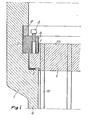
- Figure 1 is a fragmentary sectional view through a first embodiment of the invention, taken on a plane containing the longitudinal axis of the exchanger;
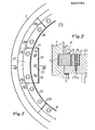
- Figure 2 is a similar sectional view through a first modified embodiment of the invention;
- Figure 3 is a plan view of one half of the segmented ring of Figure 2;
- Figure 4 is a fragmentary sectional view through a second modified embodiment of the invention, taken on a plane containing the longitudinal axis of an exchanger having two passageways at the tube side;
- Figure 5 is a fragmentary plan view of a third modified embodiment of the invention;
- Figure 6 is a sectional view taken along the line VI-VI of Figure 5;
- Figure 7 is a fragmentary plan view of the embodiment according to Figures 5 and 6, after completion of formation of the segmented ring; and
- Figure 8 is a sectional view taken along the line VIII-VIII of Figure 7.
- Throughout the cited figures, indicated at 1 is the header chamber portion of the exchanger, and at 2 the tube plate which is to be secured relatively to said header portion with the interposition of a
gasket 3 which provides a seal at the area enclosed by theshell 4 for the fluid contained therein. - With reference to Figure 1, a first embodiment of the invention will be now described; in this embodiment in the inner wall portion of the header portion 1 a
circumferential groove 5 is formed, wherein there is inserted, in accordance with a prior technique developed by this Applicant, aring 6, which is fabricated, for fitting it in place, from a number of segments. Thering 6 carries, at the annular portion projecting beyond thegroove 5, means effective to press theplate 2 against thegasket 3 , which means comprise, also according to developments by this same Applicant, a plurality ofsmall cylinders 7 guided in equally spaced holes extending substantially parallel to the longitudinal axis of the exchanger, each of them being urged with one end against thetube plate 2 by the action of ascrew 8. - The segments which make up the
ring 6 are held in place by the circumferential member comprising thelug 2a on thetube plate 2, associated at the inside diameter of saidring 6, and finally, indicated at 9 is a second segmented ring, also inserted into thegroove 5, which enables the segments of thering 6 to be fitted and disassembled, and also transfers the force developed by thepressing means ring 6 to the crown or ceiling of saidgroove 5. - From the foregoing description of this first embodiment of the invention, it should be appreciated that the absence of any retaining rings within the segmented
ring 6 enables the arrangement in the tube plate of tubes such as the one indicated at 10, which would be impossible to install where such a ring is provided, with a considerable saving in the economy of the construction. - Figures 2 and 3 illustrate a first modified embodiment of the invention; indicated at 6 therein is again the segmented ring which is inserted into the
circumferential groove 5 and comprises a plurality of segments, such as 6a,6b,6c,6d,6e, which includesmall cylinders 7 urged byscrews 8 inserted through threaded holes, such as 8a and 8b, in thesegment 6d. - The insertion in place of the individual segments, with their inside diameter mating the
lug 2a on the tube plate, is allowed, with this embodiment, by the provision of a tapering region 11 on the external surfaces thereof, as clearly visible in Figure 2,where the dash-and-dot outline shows an intermediate position of the insertion step. In other words each segment is assembled by merely slipping it in, utilizing the clearance afforded by the cutout resulting from the provision of said tapering surface. - The assembling sequence of the segments provides for the initial positioning of the segments in the arc extending between the
segment 6c andsegment 6d, these latter being excluded, and of the segments in the diametrically opposite arc, all segments being matingly limited by radial end surfaces; then, there are assembled thesegments diametrical plane 12, which are bordered by a radial surface and a surface parallel to saidplane 12, and finally the segments 6a and 6b are inserted which have both their end surfaces parallel to theplane 12, without encountering interference problems. - Of course, the segments with their end surfaces parallel to the diametrical plane may differ in number from that above specified, the provision of just one of them being sufficient, although two would be preferred, as in the solution described, or four, arranged diametrically opposite.
- If the segmented ring 6'is formed, as is customary, from a forged single workpiece, the various segments being obtained by cutting separating surfaces, then it would be necessary, in order to achieve a correct positioning of the various segments, to insert therebetween play compensating pins, such as 13, to take up the play between the
segments 6a and 6c. - The embodiment just described is highly compact, which ensures minimum axial space requirements, with favorable reflections on the size of the whole header portion of the exchanger.
- A second modified embodiment is shown in Figure 4, and again indicated at 6'is the ring inserted into the
groove 5 and being formed by several segments including thesmall cylinders 7 urged by thescrews 8. - In this case, the segments of the ring 6', which are inserted thanks to the provision of the tapering portion described hereinabove, are held in place by a circumferential member which comprises the lug 14a of the
plate 14 connected to thesleeve 15 which contacts with its other end thetube plate 2 at a minimum peripheral area, thus being allowed the obtainment of a very high value for the maximum drilling circumference diameter for the passage of tubes such as 16. - Formed in the
sleeve 15 is the divider diaphragm, which is made necessary by this being an exchanger with two passageways at the tube side, simply with the provision of thecover 17, secured by stud bolts such as 18, and of a longitudinal partition or baffle, not shown in the figure, which extends from said cover to contact thetube plate 2; moreover, indicated at 19 is an opening in the wall of thesleeve 15 and aligned with thefluid passage hole 20, and a similar opening will, of course, be present at the other fluid passage hole formed in the header portion, with suitable seals, which are not shown in the drawing for simplicity. - Should the device be used with an eacharlger having a single passageway at the tube side, the presence of the divider diaphragm is no longer necessary, thereby both the
cover 17 and partition or baffle would be omitted. - It should be noted that in the embodiment just described, the segments of the ring 6'may lack the tapering region, and in that case, the slipping thereof in place would require a second segmented ring overlying the former, as shown in Figure 1.
- With reference to Figures 5,6,7,8, a third modified embodiment of the invention is illustrated, in which the segmented ring inserted into the
circumferential groove 5, associated for holding in place thelug 2a of thetube plate 2 and provided withscrews 8 which urge small cylinders(not shown in said figures)against saidtube plate 2, is positioned in accordance with the procedure which will be presently explained with reference to Figures 5 and 6. - In said figures, indicated at 21 is a peripheral cutout in the
lug 2a of the tube plate, and shown in full lines is the position taken by one ring segment 22a inside saidcutout 21 by mere insertion with a movement in a substantially perpendicular direction to the plane of thetube plate 2. - At the position 22a, the segment will face the
circumferential groove 5, and may thus be pushed into it with a movement in a substantially radial direction until it occupies theposition 22b shown in dash-and-dot lines, to be finally pushed, as indicated by the position 22c shown in dash lines, along saidcircumferential groove 5 to occupy its final assembly position within the ring. - The segments are progressively inserted one after the other in accordance to the procedure described, and in Figures 7 and 8 the final situation is depicted, with the fully assembled ring inserted into the
groove 5 and associated with thelug 2a of the tube plate, and with thecutout 21 shut by theplug 23 secured to theplate 2 by means of thescrews - In Figure 7, it may be seen that the last segment to be inserted for completing the ring is the one indicated at 27 which has, purposely to enable its insertion, the end surfaces 27a and 27b substantially parallel to its diametrical symmetry plane, and the
segments segment 27 also have their end surfaces 28a and 29a of the same pattern, whereas theother end surfaces 28b and 29b follow a radial pattern similarly to those of all the other segments in the ring. - It is important to observe that in the invention, which achieves the greatest possible reduction in axial space requirements, the cutout or
recess 21 in the lug of the tube plate is formed at an area, as normally provided in heat exchangers, which is unoccupied by the tubes of the tube nest because it is located at the protective screen for said tubes at the inlet of the fluid at the shell side. - A highly favorable feature of all the embodiments described hereinabove is the considerable stiffening effect applied to the segmented ring by the provision of the circumferential member comprising the
lug 2a of the tube plate or 14a of theplate 14, and this enables said ring to be dimensioned with a limited thickness, and accordingly, greater compactness of the device. - All of the embodiments described further make the assembling of the segmented ring quite easy, with good reflections on the shortening of the processing time.
- The invention as described is susceptible to many modifications and variations, in addition to those described, without departing from the scope of the instant inventive concept: thus, as an example, the
screws 8 may react, rather than against as many small cylinders as are the screws themselves, against a single ring, possibly fabricated in plural segments, in contact with the tube plate. - In practicing the invention, all of the parts may be replaced with other, technically equivalent, elements; furthermore, the materials used, and the shapes and dimensions, may be any selected ones to meet individual requirements.
Claims (12)
Applications Claiming Priority (8)
| Application Number | Priority Date | Filing Date | Title |
|---|---|---|---|
| IT21968/82A IT1152977B (en) | 1982-06-21 | 1982-06-21 | PERFECTED TIGHTENING PLATE TIGHTENING DEVICE IN HEAT EXCHANGERS |
| IT2196882 | 1982-06-21 | ||
| IT2320482 | 1982-09-10 | ||
| ITMI1982U23204U IT8223204U1 (en) | 1982-10-15 | 1982-10-15 | IMPROVED TUBE PLATE TIGHTENING DEVICE IN HEAT EXCHANGERS. |
| IT23890/82A IT1152947B (en) | 1982-10-22 | 1982-10-22 | TUBE PLATE TIGHTENING DEVICE IN HEAT EXCHANGERS |
| IT2389082 | 1982-10-22 | ||
| ITMI1983U21112U IT8321112U1 (en) | 1983-03-15 | 1983-03-15 | IMPROVED TUBE PLATE TIGHTENING DEVICE IN HEAT EXCHANGERS. |
| IT2111283U | 1983-03-15 |
Publications (3)
| Publication Number | Publication Date |
|---|---|
| EP0097324A2 true EP0097324A2 (en) | 1984-01-04 |
| EP0097324A3 EP0097324A3 (en) | 1984-05-02 |
| EP0097324B1 EP0097324B1 (en) | 1988-01-27 |
Family
ID=27452833
Family Applications (1)
| Application Number | Title | Priority Date | Filing Date |
|---|---|---|---|
| EP83105860A Expired EP0097324B1 (en) | 1982-06-21 | 1983-06-15 | Clamping assembly for heat exchanger tube plates |
Country Status (3)
| Country | Link |
|---|---|
| US (1) | US4630673A (en) |
| EP (1) | EP0097324B1 (en) |
| DE (1) | DE3375505D1 (en) |
Cited By (4)
| Publication number | Priority date | Publication date | Assignee | Title |
|---|---|---|---|---|
| US4750555A (en) * | 1985-01-03 | 1988-06-14 | Alfa-Laval Thermal Ab | Device in a frame plate for a plate heat exchanger |
| EP0614064A3 (en) * | 1993-03-03 | 1995-05-10 | Nuovo Pignone Spa | Improved closure system for a heat exchanger distributor. |
| WO2007122631A3 (en) * | 2006-04-21 | 2008-09-04 | Larsen & Toubro Ltd | Sealing arrangement for internal tubesheet for tubular heat exchangers |
| WO2019183176A1 (en) | 2018-03-20 | 2019-09-26 | Lummus Technology Inc. | Heat exchanger closure assemblies and methods of using and installing the same |
Families Citing this family (6)
| Publication number | Priority date | Publication date | Assignee | Title |
|---|---|---|---|---|
| US4750554A (en) * | 1984-12-12 | 1988-06-14 | Lummus Crest, Inc. | Internal tube sheet sealing apparatus assembly for tubular heat exchangers |
| US4846262A (en) * | 1987-01-30 | 1989-07-11 | Connell Limited Partnership | Head closure apparatus for heat exchanger |
| US5362454A (en) * | 1993-06-28 | 1994-11-08 | The M. W. Kellogg Company | High temperature heat exchanger |
| PL2013559T3 (en) * | 2006-04-24 | 2013-02-28 | Larsen & Toubro Ltd | Seal for tubular heat exchanger |
| ATE495419T1 (en) * | 2006-05-09 | 2011-01-15 | Larsen & Toubro Ltd | CLOSURE FOR A THREADED CHANNEL FOR A TUBE BUNDLE HEAT EXCHANGER |
| DE102014208093A1 (en) | 2014-04-29 | 2015-10-29 | Mahle Lnternational Gmbh | Heat exchanger |
Family Cites Families (15)
| Publication number | Priority date | Publication date | Assignee | Title |
|---|---|---|---|---|
| CA615451A (en) * | 1961-02-28 | Frank Boni, Jr. | Removable tube sheet construction for heat exchangers | |
| US2009877A (en) * | 1931-03-04 | 1935-07-30 | Foster Whecler Corp | Closure for pressure vessels |
| US2060078A (en) * | 1936-02-07 | 1936-11-10 | James C Hobbs | Heat exchanger |
| US2237029A (en) * | 1938-04-09 | 1941-04-01 | Westinghouse Electric & Mfg Co | High pressure head |
| US2239912A (en) * | 1938-04-21 | 1941-04-29 | Westinghouse Electric & Mfg Co | Closure member for high pressure heads |
| US2296710A (en) * | 1938-04-23 | 1942-09-22 | Westinghouse Electric & Mfg Co | High pressure sealing head |
| GB520961A (en) * | 1938-11-04 | 1940-05-08 | Lummus Co | Improvements in or relating to tubular heat exchangers |
| US2213410A (en) * | 1938-12-15 | 1940-09-03 | Westinghouse Electric & Mfg Co | High pressure closure for pressure vessels |
| US2223320A (en) * | 1939-11-30 | 1940-11-26 | Lummus Co | Heat exchanger |
| US2290528A (en) * | 1940-05-01 | 1942-07-21 | Lummus Co | Heat exchanger |
| US2340756A (en) * | 1941-12-06 | 1944-02-01 | Heat Transfer Products Inc | Heat exchanger |
| US2956704A (en) * | 1957-05-15 | 1960-10-18 | Griscom Russell Co | Removable tube sheet construction for heat exchangers |
| GB1250566A (en) * | 1969-02-25 | 1971-10-20 | ||
| US3721291A (en) * | 1971-08-18 | 1973-03-20 | Westinghouse Electric Corp | End closure for a heat exchanger |
| NL182749C (en) * | 1979-01-30 | 1988-05-02 | Shell Int Research | HEAT EXCHANGER. |
-
1983
- 1983-06-14 US US06/504,344 patent/US4630673A/en not_active Expired - Fee Related
- 1983-06-15 DE DE8383105860T patent/DE3375505D1/en not_active Expired
- 1983-06-15 EP EP83105860A patent/EP0097324B1/en not_active Expired
Cited By (12)
| Publication number | Priority date | Publication date | Assignee | Title |
|---|---|---|---|---|
| US4750555A (en) * | 1985-01-03 | 1988-06-14 | Alfa-Laval Thermal Ab | Device in a frame plate for a plate heat exchanger |
| EP0614064A3 (en) * | 1993-03-03 | 1995-05-10 | Nuovo Pignone Spa | Improved closure system for a heat exchanger distributor. |
| WO2007122631A3 (en) * | 2006-04-21 | 2008-09-04 | Larsen & Toubro Ltd | Sealing arrangement for internal tubesheet for tubular heat exchangers |
| US8006748B2 (en) | 2006-04-21 | 2011-08-30 | Larsen & Toubro Limited | Sealing arrangement for internal tubesheet for tubular heat exchangers |
| WO2019183176A1 (en) | 2018-03-20 | 2019-09-26 | Lummus Technology Inc. | Heat exchanger closure assemblies and methods of using and installing the same |
| EP3759412A4 (en) * | 2018-03-20 | 2021-11-24 | Lummus Technology Inc. | HEAT EXCHANGER CLOSURE ASSEMBLIES AND METHODS FOR USING AND INSTALLING THE LATTER |
| CN114739227A (en) * | 2018-03-20 | 2022-07-12 | 鲁姆斯科技公司 | Heat exchanger closure assembly and method of use and installation |
| EP4276400A2 (en) | 2018-03-20 | 2023-11-15 | Lummus Technology LLC | Heat exchanger closure assemblies and methods of using and installing the same |
| US11852424B2 (en) | 2018-03-20 | 2023-12-26 | Lummus Technology Llc | Heat exchanger closure assemblies and methods of using and installing the same |
| EP4276400A3 (en) * | 2018-03-20 | 2024-03-06 | Lummus Technology LLC | Heat exchanger closure assemblies and methods of using and installing the same |
| US11971229B2 (en) | 2018-03-20 | 2024-04-30 | Lummus Technology Llc | Heat exchanger closure assemblies and methods of using and installing the same |
| US12455123B2 (en) | 2018-03-20 | 2025-10-28 | Lummus Technology Llc | Heat exchanger closure assemblies and methods of using and installing the same |
Also Published As
| Publication number | Publication date |
|---|---|
| EP0097324A3 (en) | 1984-05-02 |
| US4630673A (en) | 1986-12-23 |
| EP0097324B1 (en) | 1988-01-27 |
| DE3375505D1 (en) | 1988-03-03 |
Similar Documents
| Publication | Publication Date | Title |
|---|---|---|
| EP0097324A2 (en) | Clamping assembly for heat exchanger tube plates | |
| US5171025A (en) | Sealing arrangement for a valve and more particularly one in the form of a multi-way valve | |
| EP3695155B1 (en) | Multiple passage rotary union | |
| US3767234A (en) | Devices for interconnecting hydraulic or pneumatic conduits | |
| US4648631A (en) | Reducing coupling | |
| US3948315A (en) | Closure for heat exchanger | |
| US3305249A (en) | Quick-connect device for multiple fluid lines | |
| US5040828A (en) | Tapping sleeve | |
| US5163712A (en) | Rotatable vacuum flange | |
| US3331238A (en) | Sealing and clamping head for an end of a tube to be pressure-tested | |
| US3377087A (en) | Union for connecting conduits | |
| WO2012067760A1 (en) | Tube plug for a heat exchanger tube | |
| US2664109A (en) | Fluid circuit resistor construction | |
| US3438657A (en) | Swaged ferrule type flexible coupling | |
| JPS62159876A (en) | Fixture for thermostat | |
| US4120352A (en) | Device for connecting exchanger tubes to perforated plates | |
| SE450408B (en) | CHOOSING WITH AN OUTER COAT AND AN INTERNAL COAT BETWEEN A VERMEVEXLARVETIC FLOW | |
| US2273186A (en) | Closure for high pressure heads | |
| GB2111172A (en) | Frictional releasable shaft-hub connexion | |
| US4512496A (en) | High pressure feedwater heater closure assembly | |
| EP0033303A1 (en) | Sealing device in valve casings | |
| US4242987A (en) | Connecting arrangement for a heating boiler | |
| US4919246A (en) | Assembly of two generally annular members, in particular a diaphragm and securing member for a clutch mechanism, particularly for an automobile | |
| US4378123A (en) | Seal means for underwater connectors | |
| US1908804A (en) | Shaft packing |
Legal Events
| Date | Code | Title | Description |
|---|---|---|---|
| PUAI | Public reference made under article 153(3) epc to a published international application that has entered the european phase |
Free format text: ORIGINAL CODE: 0009012 |
|
| AK | Designated contracting states |
Designated state(s): BE CH DE FR GB LI NL SE |
|
| PUAL | Search report despatched |
Free format text: ORIGINAL CODE: 0009013 |
|
| AK | Designated contracting states |
Designated state(s): BE CH DE FR GB LI NL SE |
|
| 17P | Request for examination filed |
Effective date: 19841022 |
|
| GRAA | (expected) grant |
Free format text: ORIGINAL CODE: 0009210 |
|
| AK | Designated contracting states |
Kind code of ref document: B1 Designated state(s): BE CH DE FR GB LI NL SE |
|
| PG25 | Lapsed in a contracting state [announced via postgrant information from national office to epo] |
Ref country code: LI Effective date: 19880127 Ref country code: CH Effective date: 19880127 Ref country code: BE Effective date: 19880127 |
|
| PG25 | Lapsed in a contracting state [announced via postgrant information from national office to epo] |
Ref country code: SE Effective date: 19880131 |
|
| REF | Corresponds to: |
Ref document number: 3375505 Country of ref document: DE Date of ref document: 19880303 |
|
| ET | Fr: translation filed | ||
| REG | Reference to a national code |
Ref country code: CH Ref legal event code: PL |
|
| PLBE | No opposition filed within time limit |
Free format text: ORIGINAL CODE: 0009261 |
|
| STAA | Information on the status of an ep patent application or granted ep patent |
Free format text: STATUS: NO OPPOSITION FILED WITHIN TIME LIMIT |
|
| 26N | No opposition filed | ||
| PGFP | Annual fee paid to national office [announced via postgrant information from national office to epo] |
Ref country code: FR Payment date: 19910628 Year of fee payment: 9 |
|
| PGFP | Annual fee paid to national office [announced via postgrant information from national office to epo] |
Ref country code: NL Payment date: 19910630 Year of fee payment: 9 |
|
| PGFP | Annual fee paid to national office [announced via postgrant information from national office to epo] |
Ref country code: GB Payment date: 19910705 Year of fee payment: 9 |
|
| PGFP | Annual fee paid to national office [announced via postgrant information from national office to epo] |
Ref country code: DE Payment date: 19910726 Year of fee payment: 9 |
|
| PG25 | Lapsed in a contracting state [announced via postgrant information from national office to epo] |
Ref country code: GB Effective date: 19920615 |
|
| PG25 | Lapsed in a contracting state [announced via postgrant information from national office to epo] |
Ref country code: NL Effective date: 19930101 |
|
| GBPC | Gb: european patent ceased through non-payment of renewal fee |
Effective date: 19920615 |
|
| NLV4 | Nl: lapsed or anulled due to non-payment of the annual fee | ||
| PG25 | Lapsed in a contracting state [announced via postgrant information from national office to epo] |
Ref country code: FR Effective date: 19930226 |
|
| PG25 | Lapsed in a contracting state [announced via postgrant information from national office to epo] |
Ref country code: DE Effective date: 19930302 |
|
| REG | Reference to a national code |
Ref country code: FR Ref legal event code: ST |