EP0097324B1 - Befestigungsvorrichtung für Röhrenplatten in Wärmetauschern - Google Patents
Befestigungsvorrichtung für Röhrenplatten in Wärmetauschern Download PDFInfo
- Publication number
- EP0097324B1 EP0097324B1 EP83105860A EP83105860A EP0097324B1 EP 0097324 B1 EP0097324 B1 EP 0097324B1 EP 83105860 A EP83105860 A EP 83105860A EP 83105860 A EP83105860 A EP 83105860A EP 0097324 B1 EP0097324 B1 EP 0097324B1
- Authority
- EP
- European Patent Office
- Prior art keywords
- segmented ring
- surface portion
- groove
- lug
- circumferential
- Prior art date
- Legal status (The legal status is an assumption and is not a legal conclusion. Google has not performed a legal analysis and makes no representation as to the accuracy of the status listed.)
- Expired
Links
Images



Classifications
-
- F—MECHANICAL ENGINEERING; LIGHTING; HEATING; WEAPONS; BLASTING
- F28—HEAT EXCHANGE IN GENERAL
- F28F—DETAILS OF HEAT-EXCHANGE AND HEAT-TRANSFER APPARATUS, OF GENERAL APPLICATION
- F28F9/00—Casings; Header boxes; Auxiliary supports for elements; Auxiliary members within casings
- F28F9/02—Header boxes; End plates
- F28F9/0219—Arrangements for sealing end plates into casing or header box; Header box sub-elements
-
- F—MECHANICAL ENGINEERING; LIGHTING; HEATING; WEAPONS; BLASTING
- F28—HEAT EXCHANGE IN GENERAL
- F28F—DETAILS OF HEAT-EXCHANGE AND HEAT-TRANSFER APPARATUS, OF GENERAL APPLICATION
- F28F2275/00—Fastening; Joining
- F28F2275/08—Fastening; Joining by clamping or clipping
- F28F2275/085—Fastening; Joining by clamping or clipping with snap connection
Definitions
- This invention relates to a heat exchanger with an assembly for damping tube plates.
- the technical field of heat exchangers is known to comprise a large variety of designs wherein a tube plate is arranged to bear, with the interposition of a gasket, on a surface suitably formed on the shell end, and is clamped in that position to sealingly separate the fluid flown through the tube interiors and the fluid which sweeps the tube exteriors in flowing through the space portion enclosed by the shell.
- the devices for clamping the tube plate are quite numerous in the art, such as, to name but a few, a device which includes a plurality of stud bolts arranged around the gasket and adapted to be engaged with holes provided in the tube plate which is tightened down by means of nuts, or the one including a ring which is inserted into a peripheral groove of the tube plate, wherewith braces are associated which engage with a second ring overlying the peripheral area of said tube plate so as to compress it onto said gasket by tightening nuts provided at the brace ends.
- the ring For its insertion into the circumferential groove, the ring is fabricated in plural segments which, of course, must be held in place, and this problem is solved, in the cited device, through the use of a unitary construction retaining ring which is inserted within the segmented ring on the opposite side to that facing the tube plate.
- the task of this invention is to provide an improved device for clamping tube plates in heat exchangers, which reduces local stresses and affords the possibility of maximizing the diameter of the circumference containing the centers of the tube plate holes relating to the outermost tubes in the tube nest, thereby providing savings which, in view of the dimensions involved, may be of determining importance to the exchanger economy.
- Yet another object of this invention is to provide a clamping device, wherein the divider diaphragm, as required with exchangers having a number of passageways at the tube side which is a multiple of two, such as those comprising U-like tubes, can be fabricated in a simpler manner.
- said circumferential member is formed by a lug formation on the tube plate, and may also be formed by a lug formation on a plate connected to one end of a circumferential sleeve which is in contact with said tube plate with its other end.
- header chamber portion of the exchanger indicated at 1 is the header chamber portion of the exchanger, and at 2 the tube plate which is to be secured relatively to said header portion with the interposition of a gasket 3 onto a flat lying supporting surface 4a of the chamber portion 1 and which provides a seat at the area enclosed by the shell 4 for the fluid contained therein.
- a circumferential groove 5 is formed, having a circumferential bottom wall 5b and a shoulder defining side wall 5a both coaxial with the shell 4 of the heat exchanger.
- a ring 6 which is fabricated, for fitting it in place (i.e. for mating engagement of its surface portions 62b, 62 with contiguous surface portions 5b and 2b, 2c of the groove 5 and the lug 2a, respectively), from a number of segments.
- the ring 6 has a radial surface portion 60 penetrating the groove 5 and carries, at the annular portion 61 projecting beyond the groove 5, means effective to press the plate 2 against the gasket 3, which means comprise a plurality of small cylinders 7 guided in equally spaced holes extending substantially parallel to the longitudinal axis of the exchanger, each of them being urged with one end against the tube plate 2 by the action of a screw 8.
- the segments which make up the ring 6 are held in place by the circumferential member comprising the lug 2a on the tube plate 2, associated at the inside diameter of said ring 6.
- the association between the inside diameter of the ring 6 and the lug 2a means engagement of a lateral surface 62 defined by the inside diameter of ring 6 and a lateral surface 2b of the lug 2a.
- indicated at 9 is a second segmented ring, also inserted into the groove 5, which enables the segments of the ring 6 to be fitted and disassembled, and also transfers the force developed by the pressing means 7, 8 cooperating with said ring 6 to the crown or ceiling of said groove 5.
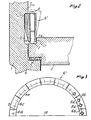
- Figures 2 and 3 illustrate a first modified embodiment of the invention; indicated at 6 therein is again the segmented ring which is inserted into the circumferential groove 5 and comprises a plurality of segments, such as 6a, 6b, 6c, 6d, 6e, which include small cylinders 7 urged by screws 8 inserted through threaded holes, such as 8a and 8b, in the segment 6d.
- segmented ring which is inserted into the circumferential groove 5 and comprises a plurality of segments, such as 6a, 6b, 6c, 6d, 6e, which include small cylinders 7 urged by screws 8 inserted through threaded holes, such as 8a and 8b, in the segment 6d.
- the assembling sequence of the segments provides for the initial positioning of the segments in the arc extending between the segment 6c and segment 6d, these latter being excluded, and of the segments in the diametrically opposite arc, all segments being matingly limited by radial end surfaces; then, there are assembled the segments 6c and 6d and their symmetrical counterparts with respect to the diametrical plane 12, which are bordered by a radial surface and a surface parallel to said plane 12, and finally the segments 6a and 6b are inserted which have both their end surfaces parallel to the plane 12, without encountering interference problems.
- the segments with their end surfaces parallel to the diametrical plane may differ in number from that above specified, the provision of just one of them being sufficient, although two would be preferred, as in the solution described, of four, arranged diametrically opposite.
- segmented ring 6' is formed, as is customary, from a forged single workpiece, the various segments being obtained by cutting separating surfaces, then it would be necessary, in order to achieve a correct positioning of the various segments, to insert therebetween play compensating pins, such as 13, to take up the play between the segments 6a and 6c.
- the embodiment just described is highly compact, which ensures minimum axial space requirements, with favorable reflections on the size of the whole header portion of the exchanger.
- a peripheral cutout in the lug 2a of the tube plate is indicated at 21 in full lines is the position taken by one ring segment inside said cutout 21 by mere insertion with a movement in a substantially perpendicular direction to the plane of the tube plate 2.
- the segment will face the circumferential groove 5, and may thus be pushed into it with a movement in a substantially radial direction until it occupies the position 22b shown in dash-and-dot lines, to be finally pushed, as indicated by the position 22c shown in dash lines, along said circumferential groove 5 to occupy its final assembly position within the ring.
- the last segment to be inserted for completing the ring is the one indicated at 27 which has, purposely to enable its insertion, the end surfaces 27a and 27b substantially parallel to its diametrical symmetry plane, and the segments 28 and 29 contiguous to the segment 27 also have their end surfaces 28a and 29a of the same pattern, whereas the other end surfaces 28b and 29b follow a radial pattern similarly to those of all the other segments in the ring.
- the cutout or recess 21 in the lug of the tube plate is formed at an area, as normally provided in heat exchangers, which is unoccupied by the tubes of the tube nest because it is located at the protective screen for said tubes at the inlet of the fluid at the shell side.
- a highly favorable feature of all the embodiments described hereinabove is the considerable stiffening effect applied to the segmented ring by the provision of the circumferential member comprising the lug 2a of the tube plate 2, and this enables said ring to be dimensionsed with a limited thickness, and accordingly, greater compactness of the device.
Landscapes
- Engineering & Computer Science (AREA)
- Physics & Mathematics (AREA)
- Thermal Sciences (AREA)
- Mechanical Engineering (AREA)
- General Engineering & Computer Science (AREA)
- Heat-Exchange Devices With Radiators And Conduit Assemblies (AREA)
Claims (10)
Applications Claiming Priority (8)
| Application Number | Priority Date | Filing Date | Title |
|---|---|---|---|
| IT21968/82A IT1152977B (it) | 1982-06-21 | 1982-06-21 | Dispositivo perfezionato di serraggio della piastra tubiera negli scambiatori di calore |
| IT2196882 | 1982-06-21 | ||
| IT2320482 | 1982-09-10 | ||
| ITMI1982U23204U IT8223204U1 (it) | 1982-10-15 | 1982-10-15 | Dispositivo perfezionato di serraggio della piastra tubiera negli scambiatori di calore. |
| IT23890/82A IT1152947B (it) | 1982-10-22 | 1982-10-22 | Dispositivo di serraggio della piastra tubiera negli scambiatori di calore |
| IT2389082 | 1982-10-22 | ||
| ITMI1983U21112U IT8321112U1 (it) | 1983-03-15 | 1983-03-15 | Dispositivo perfezionato di serraggio della piastra tubiera negli scambiatori di calore. |
| IT2111283U | 1983-03-15 |
Publications (3)
| Publication Number | Publication Date |
|---|---|
| EP0097324A2 EP0097324A2 (de) | 1984-01-04 |
| EP0097324A3 EP0097324A3 (en) | 1984-05-02 |
| EP0097324B1 true EP0097324B1 (de) | 1988-01-27 |
Family
ID=27452833
Family Applications (1)
| Application Number | Title | Priority Date | Filing Date |
|---|---|---|---|
| EP83105860A Expired EP0097324B1 (de) | 1982-06-21 | 1983-06-15 | Befestigungsvorrichtung für Röhrenplatten in Wärmetauschern |
Country Status (3)
| Country | Link |
|---|---|
| US (1) | US4630673A (de) |
| EP (1) | EP0097324B1 (de) |
| DE (1) | DE3375505D1 (de) |
Families Citing this family (10)
| Publication number | Priority date | Publication date | Assignee | Title |
|---|---|---|---|---|
| US4750554A (en) * | 1984-12-12 | 1988-06-14 | Lummus Crest, Inc. | Internal tube sheet sealing apparatus assembly for tubular heat exchangers |
| SE8500016D0 (sv) * | 1985-01-03 | 1985-01-03 | Alfa Laval Thermal Ab | Anordning vid en stativplatta for en plattvermevexlare |
| US4846262A (en) * | 1987-01-30 | 1989-07-11 | Connell Limited Partnership | Head closure apparatus for heat exchanger |
| IT1271957B (it) * | 1993-03-03 | 1997-06-10 | Nuovo Pignone Spa | Chiusura perfezionata per il distrubutore di uno scambiatore di calore |
| US5362454A (en) * | 1993-06-28 | 1994-11-08 | The M. W. Kellogg Company | High temperature heat exchanger |
| EP2013562A2 (de) * | 2006-04-21 | 2009-01-14 | Larsen & Toubro Limited | Abdichtungsanordnung für den inneren rohrboden eines röhrenförmigen wärmetauschers |
| PL2013559T3 (pl) * | 2006-04-24 | 2013-02-28 | Larsen & Toubro Ltd | Uszczelnienie do rurowego wymiennika ciepła |
| ATE495419T1 (de) * | 2006-05-09 | 2011-01-15 | Larsen & Toubro Ltd | Verschluss für einen gewindekanal für ein rohrbündelwärmetauscher |
| DE102014208093A1 (de) | 2014-04-29 | 2015-10-29 | Mahle Lnternational Gmbh | Wärmeübertrager |
| KR102721125B1 (ko) | 2018-03-20 | 2024-10-24 | 러머스 테크놀러지 엘엘씨 | 열교환기 클로저 조립체 및 이를 사용 및 설치하는 방법 |
Family Cites Families (15)
| Publication number | Priority date | Publication date | Assignee | Title |
|---|---|---|---|---|
| CA615451A (en) * | 1961-02-28 | Frank Boni, Jr. | Removable tube sheet construction for heat exchangers | |
| US2009877A (en) * | 1931-03-04 | 1935-07-30 | Foster Whecler Corp | Closure for pressure vessels |
| US2060078A (en) * | 1936-02-07 | 1936-11-10 | James C Hobbs | Heat exchanger |
| US2237029A (en) * | 1938-04-09 | 1941-04-01 | Westinghouse Electric & Mfg Co | High pressure head |
| US2239912A (en) * | 1938-04-21 | 1941-04-29 | Westinghouse Electric & Mfg Co | Closure member for high pressure heads |
| US2296710A (en) * | 1938-04-23 | 1942-09-22 | Westinghouse Electric & Mfg Co | High pressure sealing head |
| GB520961A (en) * | 1938-11-04 | 1940-05-08 | Lummus Co | Improvements in or relating to tubular heat exchangers |
| US2213410A (en) * | 1938-12-15 | 1940-09-03 | Westinghouse Electric & Mfg Co | High pressure closure for pressure vessels |
| US2223320A (en) * | 1939-11-30 | 1940-11-26 | Lummus Co | Heat exchanger |
| US2290528A (en) * | 1940-05-01 | 1942-07-21 | Lummus Co | Heat exchanger |
| US2340756A (en) * | 1941-12-06 | 1944-02-01 | Heat Transfer Products Inc | Heat exchanger |
| US2956704A (en) * | 1957-05-15 | 1960-10-18 | Griscom Russell Co | Removable tube sheet construction for heat exchangers |
| GB1250566A (de) * | 1969-02-25 | 1971-10-20 | ||
| US3721291A (en) * | 1971-08-18 | 1973-03-20 | Westinghouse Electric Corp | End closure for a heat exchanger |
| NL182749C (nl) * | 1979-01-30 | 1988-05-02 | Shell Int Research | Warmteuitwisselaar. |
-
1983
- 1983-06-14 US US06/504,344 patent/US4630673A/en not_active Expired - Fee Related
- 1983-06-15 DE DE8383105860T patent/DE3375505D1/de not_active Expired
- 1983-06-15 EP EP83105860A patent/EP0097324B1/de not_active Expired
Also Published As
| Publication number | Publication date |
|---|---|
| EP0097324A3 (en) | 1984-05-02 |
| US4630673A (en) | 1986-12-23 |
| DE3375505D1 (en) | 1988-03-03 |
| EP0097324A2 (de) | 1984-01-04 |
Similar Documents
| Publication | Publication Date | Title |
|---|---|---|
| EP0097324B1 (de) | Befestigungsvorrichtung für Röhrenplatten in Wärmetauschern | |
| US4697947A (en) | Plug connection for boring tubes | |
| US4146261A (en) | Clamping arrangement | |
| US4378124A (en) | Hydraulic coupling device | |
| US4640534A (en) | Fluid coupling assembly | |
| US4268185A (en) | Mounting attachment | |
| US4665960A (en) | Coded coupling | |
| US4648631A (en) | Reducing coupling | |
| US4040476A (en) | Keel cooler with spiral fluted tubes | |
| CA2074938A1 (en) | Pipe connection particularly on composite pipes | |
| US4889369A (en) | Adapter fitting | |
| JPS5952757B2 (ja) | 熱交換器 | |
| US4905576A (en) | Pressure cylinder | |
| US3438657A (en) | Swaged ferrule type flexible coupling | |
| JPS62159876A (ja) | サーモスタツト弁の取付具 | |
| US5472245A (en) | Warp beam flange assembly and method of manufacture | |
| US4302034A (en) | Hydraulic coupling device | |
| AU652277B2 (en) | Cone-type clamping arrangement | |
| US2903152A (en) | Closure and seal for pressure vessels | |
| GB2031546A (en) | Locking assembly for pressure valve retainers in fuel injection pumps | |
| US8006748B2 (en) | Sealing arrangement for internal tubesheet for tubular heat exchangers | |
| US4215880A (en) | Tube clamp | |
| US4512496A (en) | High pressure feedwater heater closure assembly | |
| US5000490A (en) | Adapter fitting | |
| US4919246A (en) | Assembly of two generally annular members, in particular a diaphragm and securing member for a clutch mechanism, particularly for an automobile |
Legal Events
| Date | Code | Title | Description |
|---|---|---|---|
| PUAI | Public reference made under article 153(3) epc to a published international application that has entered the european phase |
Free format text: ORIGINAL CODE: 0009012 |
|
| AK | Designated contracting states |
Designated state(s): BE CH DE FR GB LI NL SE |
|
| PUAL | Search report despatched |
Free format text: ORIGINAL CODE: 0009013 |
|
| AK | Designated contracting states |
Designated state(s): BE CH DE FR GB LI NL SE |
|
| 17P | Request for examination filed |
Effective date: 19841022 |
|
| GRAA | (expected) grant |
Free format text: ORIGINAL CODE: 0009210 |
|
| AK | Designated contracting states |
Kind code of ref document: B1 Designated state(s): BE CH DE FR GB LI NL SE |
|
| PG25 | Lapsed in a contracting state [announced via postgrant information from national office to epo] |
Ref country code: LI Effective date: 19880127 Ref country code: CH Effective date: 19880127 Ref country code: BE Effective date: 19880127 |
|
| PG25 | Lapsed in a contracting state [announced via postgrant information from national office to epo] |
Ref country code: SE Effective date: 19880131 |
|
| REF | Corresponds to: |
Ref document number: 3375505 Country of ref document: DE Date of ref document: 19880303 |
|
| ET | Fr: translation filed | ||
| REG | Reference to a national code |
Ref country code: CH Ref legal event code: PL |
|
| PLBE | No opposition filed within time limit |
Free format text: ORIGINAL CODE: 0009261 |
|
| STAA | Information on the status of an ep patent application or granted ep patent |
Free format text: STATUS: NO OPPOSITION FILED WITHIN TIME LIMIT |
|
| 26N | No opposition filed | ||
| PGFP | Annual fee paid to national office [announced via postgrant information from national office to epo] |
Ref country code: FR Payment date: 19910628 Year of fee payment: 9 |
|
| PGFP | Annual fee paid to national office [announced via postgrant information from national office to epo] |
Ref country code: NL Payment date: 19910630 Year of fee payment: 9 |
|
| PGFP | Annual fee paid to national office [announced via postgrant information from national office to epo] |
Ref country code: GB Payment date: 19910705 Year of fee payment: 9 |
|
| PGFP | Annual fee paid to national office [announced via postgrant information from national office to epo] |
Ref country code: DE Payment date: 19910726 Year of fee payment: 9 |
|
| PG25 | Lapsed in a contracting state [announced via postgrant information from national office to epo] |
Ref country code: GB Effective date: 19920615 |
|
| PG25 | Lapsed in a contracting state [announced via postgrant information from national office to epo] |
Ref country code: NL Effective date: 19930101 |
|
| GBPC | Gb: european patent ceased through non-payment of renewal fee |
Effective date: 19920615 |
|
| NLV4 | Nl: lapsed or anulled due to non-payment of the annual fee | ||
| PG25 | Lapsed in a contracting state [announced via postgrant information from national office to epo] |
Ref country code: FR Effective date: 19930226 |
|
| PG25 | Lapsed in a contracting state [announced via postgrant information from national office to epo] |
Ref country code: DE Effective date: 19930302 |
|
| REG | Reference to a national code |
Ref country code: FR Ref legal event code: ST |