EP0097327A2 - Clip de fixation en deux pièces pour toiture ou structure de parois isolées - Google Patents
Clip de fixation en deux pièces pour toiture ou structure de parois isolées Download PDFInfo
- Publication number
- EP0097327A2 EP0097327A2 EP83105882A EP83105882A EP0097327A2 EP 0097327 A2 EP0097327 A2 EP 0097327A2 EP 83105882 A EP83105882 A EP 83105882A EP 83105882 A EP83105882 A EP 83105882A EP 0097327 A2 EP0097327 A2 EP 0097327A2
- Authority
- EP
- European Patent Office
- Prior art keywords
- clip
- sidewalls
- insulation
- segment
- bottom wall
- Prior art date
- Legal status (The legal status is an assumption and is not a legal conclusion. Google has not performed a legal analysis and makes no representation as to the accuracy of the status listed.)
- Withdrawn
Links
Images


Classifications
-
- E—FIXED CONSTRUCTIONS
- E04—BUILDING
- E04D—ROOF COVERINGS; SKY-LIGHTS; GUTTERS; ROOF-WORKING TOOLS
- E04D3/00—Roof covering by making use of flat or curved slabs or stiff sheets
- E04D3/36—Connecting; Fastening
- E04D3/3601—Connecting; Fastening of roof covering supported by the roof structure with interposition of a insulating layer
- E04D3/3602—The fastening means comprising elongated profiles installed in or on the insulation layer
-
- E—FIXED CONSTRUCTIONS
- E04—BUILDING
- E04D—ROOF COVERINGS; SKY-LIGHTS; GUTTERS; ROOF-WORKING TOOLS
- E04D3/00—Roof covering by making use of flat or curved slabs or stiff sheets
- E04D3/36—Connecting; Fastening
- E04D3/3607—Connecting; Fastening the fastening means comprising spacer means adapted to the shape of the profiled roof covering
-
- E—FIXED CONSTRUCTIONS
- E04—BUILDING
- E04D—ROOF COVERINGS; SKY-LIGHTS; GUTTERS; ROOF-WORKING TOOLS
- E04D3/00—Roof covering by making use of flat or curved slabs or stiff sheets
- E04D3/36—Connecting; Fastening
- E04D3/3608—Connecting; Fastening for double roof covering or overroofing
-
- E—FIXED CONSTRUCTIONS
- E04—BUILDING
- E04D—ROOF COVERINGS; SKY-LIGHTS; GUTTERS; ROOF-WORKING TOOLS
- E04D3/00—Roof covering by making use of flat or curved slabs or stiff sheets
- E04D3/36—Connecting; Fastening
- E04D3/361—Connecting; Fastening by specially-profiled marginal portions of the slabs or sheets
- E04D2003/3615—Separate fastening elements fixed to the roof structure and consisting of parts permitting relative movement to each other, e.g. for thermal expansion
Definitions
- This invention relates to single-skin insulated roof or wall structures, and more particularly to improvements in a two-piece concealed-type attachment clip for securing panels to the structural elements of a building framework.
- Single-skin roof or wall structures are known wherein lengths of blanket-type or roll-type insulation, arranged in side-by-side relation, span across plural structural elements. Concealed attachment clips overlying and fully compressing the insulation therebeneath, are secured to the subjacent structural elements. Panel members assembled in side-by-side interlocked relation, are secured to the structural elements by the concealed attachment clips. The full compression of the insulation at each clip site reduces the thermal efficiency of the structure. See for example U. S. Pat. No. 4,139,974 (FOX).
- Substantially incompressible thermal spacers have been provided along the structural elements between adjacent clips.
- the thermal spacer provides support for the subsequently installed panels and adds to the thermal efficiency of the structure. See for example U. S. Pat. No. 4,213,282 (HECKELSBERG) and the RIBLOCK system illustrated and described on Page 92 of "Metal Building Review", Volume 16, No. 5, May, 1980.
- the thermal spacers constitute additional elements to be installed thereby increasing the materials cost, the erection time, and consequently the overall cost of the roof or wall structure.
- the principal object of this invention is to provide a two-piece clip assembly for use in and for improving the thermal efficiency of an insulated wall or roof structure.
- Another object of this invention is to provide an improved two-piece clip assembly which eliminates the need for expensive subgirt and stand-off support systems.
- the present invention provides improvements in an insulated roof or wall structure of the type having horizontally extending, spaced-apart structural elements; compressible insulation spanning transversely across the structural elements; plural panel members overlying the insulation, spanning transversely across the structural elements, and being erected in side-by-side relation, the panel members presenting alternating panel webs and upstanding, downwardly opening longitudinal ribs each presenting an entrance opening and spaced-apart latching shoulders on opposite sides of the opening; and two-piece clip assembly securing the ribs to the structural elements.
- Each of the clip assemblies includes a U-base clip having a bottom wall and upstanding sidewalls, and flexible connecting means carried at the upper ends of the sidewalls and interengaged with the latching shoulders of an associated rib, thereby connecting the rib to the structural element.
- the bottom wall of the clip is secured to the subjacent structural element and fully compresses the underlying insulation.
- each of the clip-stabilizing portions includes a horizontal upper segment supporting the overlying panel and, connected thorato, horizontal lower segment which is vertically spaced from the structural element and from the upper segment.
- the lower segments are spaced-apart 'from the adjacent sidewalls and partially compress the underlying insulation.
- the lower segments being widely spaced-apart -- introduce lateral stability into the U-shaped base clip. Therefore the bottom wall may be relatively narrow (less than 7/8") and, as a result, the thermal degradation due to full compression of the insulation is significantly reduced.
- FIGURE 1 illustrates a two-piece clip assembly 20 comprising a U-shaped base clip 22 and flexible connecting means, such as, a top clip 24, positioned in relation to an intermediate panel rib 26.
- the U -shaped base clip 22 comprises a bottom wall 28 provided with a central screw- receiving aperture 30; upstanding sidewalls 32, 34; and integral clip-stabilizing portions 36, 38, one extending laterally outwardly from each of the sidewalls 32, 34.
- Each of the clip-stabilizing portions 36, 38 includes a horizontal upper segment 40, a horizontal lower segment 42 and an intermediate segment 44 connecting the upper segment 40 to the lower segment 42.
- the base clip 22 may be formed from 18 gauge (1.311 mm) galvanized steel.
- the base clip 22 preferably is formed from a single sheet wherein the clip-stabilizing portions are pierced from the sidewalls 32, 34.
- the base clip 22 is similar to that disclosed and claimed in copending application ser. no. 249,062 (BOYER) filed March 30, 1981 and assigned to the assignee of this invention.
- the base clip 22 differs from that of copending application ser. no. 249,062 in two respects. That is, the clip 22 has a greater height, and the clip-stabilizing portions 36, 38 have been added.
- each of the lower segments 42 is outwardly spaced-apart from the adjacent sidewalls 32, 34 and extends outwardly beyond the associated upper segment 40.
- the widely spaced-apart positions of the lower segments 42 enhances the lateral stability of the clip 22, that is, enhances the resistance to rocking of the clip 22 in the plane of the drawing.
- the bottom wall 28 may be relatively narrow.
- the width of the bottom wall 22 is less than 7/8".
- the lower segments 42 are adjacent to but vertically spaced-apart from a plane (dash-dot line P) of the lower face 46 of the bottom wall 28.
- the lower segments preferably lie in a common plane (not illustrated) generally parallel with the plane P.
- insulation is partially compressed between each of the lower segments 42 and a structural element whose upper face corresponds to the plane P. While the insulation is not fully compressed at these locations, it is compressed enough to resist lateral forces and to transfer the same from the lower segments 42 through the clip 22 to the structural element.
- the upper ends of the sidewalls 32, 34 are provided with oppositely extending slots 48 which receive inturned flanges 50 presented by the top clip 24.
- the top clip 24 shown in phantom outline with the inturned flanges 50 thereof engaged in the slots 48.
- the top clip 24 is supported by the flange-to-slot connections for limited movement transversely of the sidewalls 32, 34.
- the panel rib 26 (FIGURE 1) includes a crest 52, depending rib sidewalls 54 and reverse-turned base portions 56 connecting the rib sidewalls 54 to adjacent panel webs 58.
- the base portions 56 define an entrance opening 60 and present latching shoulders 62.
- the top clip 24 presents a downwardly depending clamping wings 64 which terminate in clamping edges 66 extending generally parallel with the length of the rib 26 and are positioned to engage the latching shoulders 62 thereby connecting the rib 26 to the base clip 22.
- the clamping wings 64 are flexed toward each other and thereafter move away from each other such that the clamping edges 66 are resiliently engaged with the latching shoulders 62. Consequently, the top clip 24 preferably is formed from spring steel having a thickness of from 18 gauge (1.214 mm) to about 22 gauge (0.760 mm).
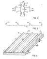
- FIGURE 5 there is illustrated a panel. member 68 presenting two intermediate ribs 26, and male and female partial ribs 70, 72 along the opposite edges thereof.
- Each of the partial ribs 70, 72 is overlappable and interfittable with a complementary partial rib 72, 70 of an adjacent panel member to provide a joint rib such as identified at 74 in FIGURES 6, 7 having a cross-sectional configuration duplicating that of the intermediate ribs 26.
- FIGURE 6 illustrates a roof or wall structure 76 having horizontally extending, spaced-apart structural elements 78 provided by the structural framework of a building.
- Blanket-type or roll-type compressible insulation 80 spans transversely across and between the structural elements 78.
- Plural panel members 68A, 68B overlie the insulation, span transversely across the structural elements 78 and are erected in side-by-side relation and are interlocked at the joint rib 74.
- the intermediate rib 26 is connected to the structural elements 78 by the clip assembly 20 wherein the top clip 24 thereof may undergo limited transverse movement relative to the base clip 22.
- the transverse movement of the top clip 24 is limited by engagement of relatively narrow tabs 82 (only one visible) with the sidewalls of the base clip 22.
- the joint rib 74 is connected to the structural element 78 by a clip assembly 20' wherein the top clip 24 thereof is substantially immovable relative to the base clip 22.
- the top clip 24 is fixed relative to the base clip 22 by relatively wide tabs 84 (only one visible in FIGURE 7) having a width substantially equal to the distance between the upstanding sidewalls 32, 34.
- Each of the base clips 22 is secured to the structural element 78 by a positive fastener 86.
- the horizontal upper segments 40 support the panel webs 58 on opposite sides of each intermediate rib 26 and of the joint rib 74. It will be observed that once each base clip 22 is installed, only that portion of the insulation 80 directly beneath the relatively narrow bottom wall 28 is fully compressed, whereas those portions of the insulation 80 directly beneath the lower horizontal segments 42 are partially compressed. Thus in the regions beneath the lower segments 42, the insulation is not totally compressed but is compressed enough to resist lateral forces applied to the clip assembly 20 and to transfer the same to the structural element 78.
- the arrangement is such that the clip assembly resists lateral forces induced during installation of the panel members; and to resist lateral roof loads such as exist due to dead and live loads.
- the bottom wall 28 of the clip 22 is not a wide element but, instead, is a relatively narrow element. In a commercial embodiment, the width of the bottom wall 28 is less than 7/8".
Landscapes
- Engineering & Computer Science (AREA)
- Mechanical Engineering (AREA)
- Architecture (AREA)
- Civil Engineering (AREA)
- Structural Engineering (AREA)
- Roof Covering Using Slabs Or Stiff Sheets (AREA)
Applications Claiming Priority (2)
| Application Number | Priority Date | Filing Date | Title |
|---|---|---|---|
| US06/389,845 US4466224A (en) | 1982-06-18 | 1982-06-18 | Two-piece attachment clip for insulated roof or wall structure |
| US389845 | 1995-02-17 |
Publications (2)
| Publication Number | Publication Date |
|---|---|
| EP0097327A2 true EP0097327A2 (fr) | 1984-01-04 |
| EP0097327A3 EP0097327A3 (fr) | 1984-08-29 |
Family
ID=23539973
Family Applications (1)
| Application Number | Title | Priority Date | Filing Date |
|---|---|---|---|
| EP83105882A Withdrawn EP0097327A3 (fr) | 1982-06-18 | 1983-06-15 | Clip de fixation en deux pièces pour toiture ou structure de parois isolées |
Country Status (3)
| Country | Link |
|---|---|
| US (1) | US4466224A (fr) |
| EP (1) | EP0097327A3 (fr) |
| DE (1) | DE97327T1 (fr) |
Cited By (5)
| Publication number | Priority date | Publication date | Assignee | Title |
|---|---|---|---|---|
| GB2210646A (en) * | 1987-10-03 | 1989-06-14 | Catnic Ltd | Partition or post fixing clip |
| GB2236547A (en) * | 1989-10-03 | 1991-04-10 | Ward Building Systems Ltd | Sheet cladding system |
| FR2661931A1 (fr) * | 1990-05-14 | 1991-11-15 | Etanco Lr | Element de fixation pour couverture ondulee utilisee dans les batiments divers. |
| EP0476524A1 (fr) * | 1990-09-14 | 1992-03-25 | ISCOM S.r.l. | Procédé de fixation d'une couverture en tôle ondulée, agencement de couverture selon ce procédé et appareil pour sa mise en oeuvre |
| AU700043B2 (en) * | 1994-08-23 | 1998-12-17 | Stramit Corporation Pty Limited | Clip for concealed fixed decks |
Families Citing this family (28)
| Publication number | Priority date | Publication date | Assignee | Title |
|---|---|---|---|---|
| US4597234A (en) * | 1979-11-13 | 1986-07-01 | Harold Simpson, Inc. | Standing seam roof assembly |
| US4594823A (en) * | 1982-09-29 | 1986-06-17 | Hague James G | Panel support assembly for concealed fastener roof structure |
| US4741139A (en) * | 1985-10-02 | 1988-05-03 | Henry Fred Campbell | Prefabricated building panel |
| US4747249A (en) * | 1985-11-01 | 1988-05-31 | Amca International Corporation | Subpurlin and attachment assembly |
| US4676042A (en) * | 1985-11-01 | 1987-06-30 | Amca International Corporation | Subpurlin and attachment assembly |
| US4791770A (en) * | 1985-11-01 | 1988-12-20 | Amca International Corporation | Subpurlin and attachment assembly |
| KR960009276B1 (en) * | 1990-10-18 | 1996-07-16 | Kantan Beauty Ind K K | Double joining roof-structure |
| US5636488A (en) * | 1993-06-23 | 1997-06-10 | Stramit Corporation Limited | Panel and clip arrangement |
| US5321927A (en) * | 1993-06-28 | 1994-06-21 | Butler Manufacturing Company | Mid-roof anchoring system |
| US5524409A (en) * | 1994-12-02 | 1996-06-11 | Kaiser; Heinz W. | Roofing and siding panel construction |
| US5811167A (en) * | 1996-01-25 | 1998-09-22 | W. L. Gore & Associates, Inc. | Packaged insulation and method of making same |
| US6240682B1 (en) | 1998-10-19 | 2001-06-05 | V.P. Buildings, Inc. | Roof bracket |
| US6543197B2 (en) | 2001-08-10 | 2003-04-08 | Arrow Group Industries, Inc. | Snap-fit panel connection apparatus |
| US7712273B2 (en) * | 2005-01-25 | 2010-05-11 | Illinois Tool Works Inc. | Thermal breaker structures for use with roof decking assemblies |
| CN101227988B (zh) * | 2005-06-21 | 2012-01-25 | 布卢斯科普钢铁有限公司 | 屋顶包层板及屋顶包层组件 |
| US8505261B2 (en) * | 2007-08-28 | 2013-08-13 | BlueScope Buildings North America | Sliding roof seam construction |
| GB0900656D0 (en) * | 2009-01-16 | 2009-02-25 | Toy John | Cladding support bracket |
| USD668357S1 (en) | 2011-03-31 | 2012-10-02 | Firestone Building Products Company, Llc | Wall panel |
| USD668353S1 (en) | 2011-03-31 | 2012-10-02 | Firestone Building Products Company, Llc | Wall panel |
| USD668354S1 (en) | 2011-03-31 | 2012-10-02 | Firestone Building Products Company, Llc | Wall panel |
| USD668356S1 (en) | 2011-03-31 | 2012-10-02 | Firestone Building Products Company, Llc | Wall panel |
| USD667963S1 (en) | 2011-03-31 | 2012-09-25 | Firestone Building Products Company, Llc | Wall panel |
| US8875453B2 (en) | 2012-06-15 | 2014-11-04 | Kanzo, Inc. | System for mounting solar modules |
| CN104870729B (zh) * | 2012-11-16 | 2018-07-24 | 蓝野钢铁有限公司 | 用于屋顶包覆板的端部搭接系统 |
| US9664217B2 (en) * | 2013-08-06 | 2017-05-30 | Sukup Manufacturing Co. | Foldable clip |
| JP6632386B2 (ja) * | 2016-01-18 | 2020-01-22 | 三晃金属工業株式会社 | 建築用受具及びその嵌合外囲体 |
| WO2018137001A1 (fr) * | 2017-01-26 | 2018-08-02 | Paul Addison | Agrafe pour feuille de métal |
| US11920355B2 (en) * | 2021-12-23 | 2024-03-05 | 0776425 B.C. Ltd. | Building material attachment devices, systems, and associated methods of manufacture and use |
Family Cites Families (11)
| Publication number | Priority date | Publication date | Assignee | Title |
|---|---|---|---|---|
| US2765887A (en) * | 1952-02-05 | 1956-10-09 | Ontwikkelingmij Polynorm Amers | Profilated covering element of channel shaped cross section for walls, roofs and the like |
| US3387872A (en) * | 1966-07-19 | 1968-06-11 | Nat Gypsum Co | Imitation ceiling beam attachment clip |
| GB1350518A (en) * | 1971-05-26 | 1974-04-18 | Lysaght Australia Ltd | Sheet cladding system |
| GB1387272A (en) * | 1971-10-08 | 1975-03-12 | Cookson Sheet Metal Dev Ltd | Sheet fixing devices |
| US4102105A (en) * | 1975-05-29 | 1978-07-25 | Armco Steel Corporation | Interlocked channel section panels and connectors therefor |
| US3998019A (en) * | 1975-08-18 | 1976-12-21 | Illinois Tool Works Inc. | Roof panel fastener and joint construction |
| US4139974A (en) * | 1976-09-07 | 1979-02-20 | Atlanta Metal Products, Inc. | Standing T-rib roof system |
| US4099356A (en) * | 1976-10-07 | 1978-07-11 | Alcan Aluminum Corporation | Seamed rib panel assembly |
| US4213282A (en) * | 1978-02-06 | 1980-07-22 | Amca International Corporation | Metal panel roofing structure |
| US4269012A (en) * | 1979-02-01 | 1981-05-26 | The Binkley Company | Standing seam roof, panel therefor, and method of installation |
| US4400922A (en) * | 1981-03-30 | 1983-08-30 | H. H. Robertson Company | Panel mounting clip assembly and wall or roof structure utilizing the same |
-
1982
- 1982-06-18 US US06/389,845 patent/US4466224A/en not_active Expired - Lifetime
-
1983
- 1983-06-15 EP EP83105882A patent/EP0097327A3/fr not_active Withdrawn
- 1983-06-15 DE DE198383105882T patent/DE97327T1/de active Pending
Cited By (7)
| Publication number | Priority date | Publication date | Assignee | Title |
|---|---|---|---|---|
| GB2210646A (en) * | 1987-10-03 | 1989-06-14 | Catnic Ltd | Partition or post fixing clip |
| GB2210646B (en) * | 1987-10-03 | 1991-07-31 | Catnic Ltd | Improvements in or relating to fixing devices for hollow structural components |
| GB2236547A (en) * | 1989-10-03 | 1991-04-10 | Ward Building Systems Ltd | Sheet cladding system |
| GB2236547B (en) * | 1989-10-03 | 1993-12-22 | Ward Building Systems Ltd | Sheet cladding system |
| FR2661931A1 (fr) * | 1990-05-14 | 1991-11-15 | Etanco Lr | Element de fixation pour couverture ondulee utilisee dans les batiments divers. |
| EP0476524A1 (fr) * | 1990-09-14 | 1992-03-25 | ISCOM S.r.l. | Procédé de fixation d'une couverture en tôle ondulée, agencement de couverture selon ce procédé et appareil pour sa mise en oeuvre |
| AU700043B2 (en) * | 1994-08-23 | 1998-12-17 | Stramit Corporation Pty Limited | Clip for concealed fixed decks |
Also Published As
| Publication number | Publication date |
|---|---|
| DE97327T1 (de) | 1984-05-10 |
| EP0097327A3 (fr) | 1984-08-29 |
| US4466224A (en) | 1984-08-21 |
Similar Documents
| Publication | Publication Date | Title |
|---|---|---|
| US4466224A (en) | Two-piece attachment clip for insulated roof or wall structure | |
| US4069636A (en) | Insulation supporting strap | |
| US4651489A (en) | Insulated roofing structure | |
| US5557903A (en) | Mounting clip for paneled roof | |
| CA1039919A (fr) | Panneaux de charpente | |
| US5181360A (en) | Standing-seam roof panel system | |
| US3662509A (en) | Insulated roof structure | |
| US4649689A (en) | Insulation fastener system | |
| US4135342A (en) | Insulated metal roofing and siding system | |
| US5911663A (en) | Support clip for roofing panels and associated system | |
| US3513614A (en) | Method for constructing an insulated roof structure | |
| EP0062756A1 (fr) | Dispositif de fixation pour des panneaux et structure de paroi ou de toiture utilisant celui-ci | |
| US4435937A (en) | Concealed fastener support for interlocked channel section panels | |
| GB2122234A (en) | Insulated roof | |
| US4089145A (en) | Metal roof construction | |
| US12320124B2 (en) | Insulated roof systems, support members thereof, and method of installing | |
| US4506479A (en) | Roof or wall covering and mounting member for a gutter bracket | |
| US4138808A (en) | Retainer clip for insulation or the like | |
| US3394519A (en) | Building wall structure | |
| US4747249A (en) | Subpurlin and attachment assembly | |
| US4791770A (en) | Subpurlin and attachment assembly | |
| US4676042A (en) | Subpurlin and attachment assembly | |
| US8453409B2 (en) | Spacer | |
| US4574549A (en) | Adjustable roof insulation system | |
| EP0011202B1 (fr) | Fixation d'éléments de construction pour murs ou toits |
Legal Events
| Date | Code | Title | Description |
|---|---|---|---|
| PUAI | Public reference made under article 153(3) epc to a published international application that has entered the european phase |
Free format text: ORIGINAL CODE: 0009012 |
|
| AK | Designated contracting states |
Designated state(s): AT BE CH DE FR LI LU NL |
|
| TCAT | At: translation of patent claims filed | ||
| EL | Fr: translation of claims filed | ||
| TCNL | Nl: translation of patent claims filed | ||
| RAP1 | Party data changed (applicant data changed or rights of an application transferred) |
Owner name: ROBERTSON BAUELEMENTE GMBH |
|
| DET | De: translation of patent claims | ||
| PUAL | Search report despatched |
Free format text: ORIGINAL CODE: 0009013 |
|
| AK | Designated contracting states |
Designated state(s): AT BE CH DE FR LI LU NL |
|
| 17P | Request for examination filed |
Effective date: 19850222 |
|
| STAA | Information on the status of an ep patent application or granted ep patent |
Free format text: STATUS: THE APPLICATION IS DEEMED TO BE WITHDRAWN |
|
| 18D | Application deemed to be withdrawn |
Effective date: 19851231 |
|
| RIN1 | Information on inventor provided before grant (corrected) |
Inventor name: HAGUE, JAMES G. |