EP0097385B1 - Messgerät - Google Patents
Messgerät Download PDFInfo
- Publication number
- EP0097385B1 EP0097385B1 EP83200716A EP83200716A EP0097385B1 EP 0097385 B1 EP0097385 B1 EP 0097385B1 EP 83200716 A EP83200716 A EP 83200716A EP 83200716 A EP83200716 A EP 83200716A EP 0097385 B1 EP0097385 B1 EP 0097385B1
- Authority
- EP
- European Patent Office
- Prior art keywords
- pendulum
- cable
- situated
- point
- measuring
- Prior art date
- Legal status (The legal status is an assumption and is not a legal conclusion. Google has not performed a legal analysis and makes no representation as to the accuracy of the status listed.)
- Expired
Links
- 239000007788 liquid Substances 0.000 claims description 39
- 230000010355 oscillation Effects 0.000 claims description 19
- 239000012858 resilient material Substances 0.000 claims description 3
- 238000000034 method Methods 0.000 claims description 2
- 229920003002 synthetic resin Polymers 0.000 claims description 2
- 239000000057 synthetic resin Substances 0.000 claims description 2
- 238000005259 measurement Methods 0.000 description 8
- 230000001133 acceleration Effects 0.000 description 4
- 238000000926 separation method Methods 0.000 description 3
- 239000007789 gas Substances 0.000 description 2
- 230000000903 blocking effect Effects 0.000 description 1
- 238000013016 damping Methods 0.000 description 1
- 238000004880 explosion Methods 0.000 description 1
- 238000007654 immersion Methods 0.000 description 1
- 230000001939 inductive effect Effects 0.000 description 1
- 239000000463 material Substances 0.000 description 1
- 230000003449 preventive effect Effects 0.000 description 1
- 238000001228 spectrum Methods 0.000 description 1
- 239000000725 suspension Substances 0.000 description 1
- 238000004804 winding Methods 0.000 description 1
Images


Classifications
-
- G—PHYSICS
- G01—MEASURING; TESTING
- G01F—MEASURING VOLUME, VOLUME FLOW, MASS FLOW OR LIQUID LEVEL; METERING BY VOLUME
- G01F23/00—Indicating or measuring liquid level or level of fluent solid material, e.g. indicating in terms of volume or indicating by means of an alarm
- G01F23/22—Indicating or measuring liquid level or level of fluent solid material, e.g. indicating in terms of volume or indicating by means of an alarm by measuring physical variables, other than linear dimensions, pressure or weight, dependent on the level to be measured, e.g. by difference of heat transfer of steam or water
- G01F23/28—Indicating or measuring liquid level or level of fluent solid material, e.g. indicating in terms of volume or indicating by means of an alarm by measuring physical variables, other than linear dimensions, pressure or weight, dependent on the level to be measured, e.g. by difference of heat transfer of steam or water by measuring the variations of parameters of electromagnetic or acoustic waves applied directly to the liquid or fluent solid material
- G01F23/296—Acoustic waves
- G01F23/2966—Acoustic waves making use of acoustical resonance or standing waves
-
- G—PHYSICS
- G01—MEASURING; TESTING
- G01D—MEASURING NOT SPECIALLY ADAPTED FOR A SPECIFIC VARIABLE; ARRANGEMENTS FOR MEASURING TWO OR MORE VARIABLES NOT COVERED IN A SINGLE OTHER SUBCLASS; TARIFF METERING APPARATUS; MEASURING OR TESTING NOT OTHERWISE PROVIDED FOR
- G01D5/00—Mechanical means for transferring the output of a sensing member; Means for converting the output of a sensing member to another variable where the form or nature of the sensing member does not constrain the means for converting; Transducers not specially adapted for a specific variable
- G01D5/02—Mechanical means for transferring the output of a sensing member; Means for converting the output of a sensing member to another variable where the form or nature of the sensing member does not constrain the means for converting; Transducers not specially adapted for a specific variable using mechanical means
- G01D5/08—Reducing the effects of friction, e.g. by applying vibrations
-
- G—PHYSICS
- G01—MEASURING; TESTING
- G01F—MEASURING VOLUME, VOLUME FLOW, MASS FLOW OR LIQUID LEVEL; METERING BY VOLUME
- G01F23/00—Indicating or measuring liquid level or level of fluent solid material, e.g. indicating in terms of volume or indicating by means of an alarm
- G01F23/0023—Indicating or measuring liquid level or level of fluent solid material, e.g. indicating in terms of volume or indicating by means of an alarm with a probe suspended by a wire or thread
-
- G—PHYSICS
- G01—MEASURING; TESTING
- G01F—MEASURING VOLUME, VOLUME FLOW, MASS FLOW OR LIQUID LEVEL; METERING BY VOLUME
- G01F23/00—Indicating or measuring liquid level or level of fluent solid material, e.g. indicating in terms of volume or indicating by means of an alarm
- G01F23/22—Indicating or measuring liquid level or level of fluent solid material, e.g. indicating in terms of volume or indicating by means of an alarm by measuring physical variables, other than linear dimensions, pressure or weight, dependent on the level to be measured, e.g. by difference of heat transfer of steam or water
- G01F23/28—Indicating or measuring liquid level or level of fluent solid material, e.g. indicating in terms of volume or indicating by means of an alarm by measuring physical variables, other than linear dimensions, pressure or weight, dependent on the level to be measured, e.g. by difference of heat transfer of steam or water by measuring the variations of parameters of electromagnetic or acoustic waves applied directly to the liquid or fluent solid material
- G01F23/296—Acoustic waves
- G01F23/2966—Acoustic waves making use of acoustical resonance or standing waves
- G01F23/2967—Acoustic waves making use of acoustical resonance or standing waves for discrete levels
-
- G—PHYSICS
- G01—MEASURING; TESTING
- G01K—MEASURING TEMPERATURE; MEASURING QUANTITY OF HEAT; THERMALLY-SENSITIVE ELEMENTS NOT OTHERWISE PROVIDED FOR
- G01K5/00—Measuring temperature based on the expansion or contraction of a material
- G01K5/48—Measuring temperature based on the expansion or contraction of a material the material being a solid
- G01K5/50—Measuring temperature based on the expansion or contraction of a material the material being a solid arranged for free expansion or contraction
-
- G—PHYSICS
- G01—MEASURING; TESTING
- G01N—INVESTIGATING OR ANALYSING MATERIALS BY DETERMINING THEIR CHEMICAL OR PHYSICAL PROPERTIES
- G01N11/00—Investigating flow properties of materials, e.g. viscosity, plasticity; Analysing materials by determining flow properties
- G01N11/10—Investigating flow properties of materials, e.g. viscosity, plasticity; Analysing materials by determining flow properties by moving a body within the material
-
- G—PHYSICS
- G01—MEASURING; TESTING
- G01N—INVESTIGATING OR ANALYSING MATERIALS BY DETERMINING THEIR CHEMICAL OR PHYSICAL PROPERTIES
- G01N9/00—Investigating density or specific gravity of materials; Analysing materials by determining density or specific gravity
- G01N9/002—Investigating density or specific gravity of materials; Analysing materials by determining density or specific gravity using variation of the resonant frequency of an element vibrating in contact with the material submitted to analysis
-
- G—PHYSICS
- G01—MEASURING; TESTING
- G01N—INVESTIGATING OR ANALYSING MATERIALS BY DETERMINING THEIR CHEMICAL OR PHYSICAL PROPERTIES
- G01N2291/00—Indexing codes associated with group G01N29/00
- G01N2291/02—Indexing codes associated with the analysed material
- G01N2291/028—Material parameters
- G01N2291/02836—Flow rate, liquid level
Definitions
- This invention relates to a measuring apparatus, more particularly to an apparatus allowing dynamically measuring the properties of a liquid such as the amount, the density, the viscosity and, if desired, the temperature.
- the invention aims: measuring liquid levels with respect to one or several index marks; measuring density separation surfaces in the liquids and determining said surfaces with respect to one or several index marks; measuring densities of liquids at various levels; measuring viscosities of liquids at various levels; measuring temperatures of liquids at various levels; measuring the vertical dimensions of the liquid container or the liquid channels, as well as the height differences with respect to the liquid levels and/or the density separation surfaces.
- the apparatus according to the invention will be advantageously used in any kind of liquid containers or channels, more particularly when vapours and/or gases likely to form an explosion danger and against which preventive steps must be taken, may exist or can occur, momentarily or permanently above the liquid, as well as when storing liquids and/or gases the pressure of which is higher than the atmospheric pressure.
- the apparatus according to the invention allowing the above-mentioned measurements and still others uses a principle known per se, namely the measurement of the tension created in a cable, a rope or similar by means of oscillations induced in the said cable or rope.
- a measuring apparatus comprising a pendulum whose oscillation frequency or/and amplitude variations are determinant for the measurement is known of the German patent application DE-A-2 012 475.
- the frequency or/and amplitude variations are in this case based on the friction of the pendulum with the liquid and not on the tension created in a cable.
- the apparatus which is namely capable of meeting the above mentioned requirements, comprises a pendulum actuating means for causing said pendulum to oscillate continuously; a logic control unit to control said actuating means; a position measuring device; a cable-like element which is secured at one of its ends to the position measuring device; a measuring body secured on the free end of said cable-like element, presenting such a weight that the latter is subjected to a force which is sufficiently high to maintain it in a tight state, said pendulum being forced towards its rest position by the tension in the cable-like element, said logic control unit being also arranged to receive and process a signal representative of the oscillation frequency of the pendulum; means for adjusting the position measuring device in such a way that the measuring body can be shifted in the vessel over the whole measuring range, the position measuring device being adapted to measure the position of the body in the vessel, the pendulum oscillation frequency, which is function of the apparent weight of the body, being indicative of one or more of said liquid properties.
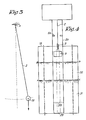
- the apparatus comprises a position measuring device 1 formed by a drum; a cable- like element 2 such as a strand, a rope, a tape, a cable or similar; a measuring body 3; a pendulum 4 and a mechanical filter 5.
- the cable-like element 2 is namely guided between first and second stationary guiding means 6-7 and 8-9, third guiding means 10 and leading means 11-12 secured on the pendulum 4.
- the drum 1 is dimensioned so that it may receive an amount of the cable-like element 2 allowing the shifting of the measuring body 3 on the whole measuring height. It may be provided with a helical groove in order to obtain a high accuracy.
- the cable-like element 2 must be sufficiently thin and flexible to remain tight under the influence of the minimum force being detected, which is the case, e.g. when detecting the lower bottom of a liquid container. It must be also sufficiently strong to resist the maximum force being detected, which is the case, e.g. when detecting the upper bottom of the container.
- the cable-like element 2 must be capable of blocking the winding system without being distorted or broken.
- the aimed accuracy determines the admissible elongation of the strand under a mechanical load, as well as the admissible expansion of the strand under the influence of the room temperature.
- the measuring body 3 will have preferably a cylindrical shape. It is made of a material the specific weight of which is such that, when immerging the said body 3 in a liquid the density of which is the highest one being provided, the latter subjects the said cable-like element to a force which is sufficiently high to maintain the cable-like element 2 in a tight state.
- the said body 3 will be finished so that, when it is removed from the liquid, it carries away the minimum amount of liquid.
- the pendulum 4 allowing to convert the tension in the cable-like element 2 into a measuring signal will be brought to its rest position through the cable-like element 2 with a force which is function of the weight with which the cable-like element is loaded, i.e. the apparent weight of the measuring body 3.
- the oscillation of the pendulum 4 is obtained and held through to a logic control unit which is also capable of recording and treating the resonance signals of the pendulum 4.
- the oscillation of the pendulum 4 is obtained through a permanent magnet (not shown in the drawings) secured on the axis 14 and capable of being actuated through an electromagnet connected with the said logic control unit.
- the said logic control unit consist of a microprocessor controlling both the position of the body 3 and the oscillation of the pendulum 4 and treating the resonance signals of the pendulum 4.
- a control unit can make measuring available to each concerned person and it is capable of receiving controls and possibly parameters valuable for the system.
- the purpose of the mechanical filter 5 is to prevent acceleration forces in the cable-like element 2 resulting from oscillations of the pendulum 4 from acting on the body 3.
- the reasonance frequency of the elements 3-5 must be suitably damped so that it does not influence the function of the pendulum 4 and it must be outside the frequency band which is axially generated by the pendulum 4 in the cable-like element 2.
- the mechanical filter 5 may be of any resilient material such as an artificial or synthetic resin, a spring or similar.
- the pendulum 4 is provided with a measuring body 3 which will influence the said return torque and, accordingly, the frequency.
- the apparatus according to the invention allows to measure various properties of a liquid and it operates as described hereafter.
- the oscillation frequency of the pendulum 4 is determined by the weight of the measuring body 3. In fact, when said body 3 is immerged in a liquid, the apparent weight is lowered, thereby reducing the said frequency.
- FIG. 4 A current application of a measuring apparatus according to the invention is shown in Figure 4.
- This figure shows a vessel 19 provided with an apparatus according to the invention which, in this example, is mounted on the upper end of a tube 20.
- the latter is preferably extended into the vessel 19 in order to form a guiding means for the measuring body 3.
- the inside of said tube 20 is permanently communicating with the content of the vessel, e.g. by means of a slit provided on the whole height of the container 19.
- the said content consists namely of two liquids 21, 22 respectively having different densities, the levels of which are situated on the lines A-A and B-B.
- the said tube 20 comprises preferably two stops 23-24 respectively used as reference points.
- said stops are not necessary because the bottom 25 of the vessel and the lower portion of the apparatus according to the invention may also function as stops.
- the value fr1 of said frequence corresponds to that position of the measuring body 3 and it is sufficient to inform the adjusting system (microprocessor) about this value. Accordingly, said reference point corresponds to a height difference of zero.
- the determination of the lower index point (stop 23 or bottom 25) is carried out in the same manner, except that the contact of the body 3 with the stop 23 or the bottom 25 causes an apparent decrease of the weight of the measuring body 3 and, accordingly, a reduction of the resonance frequency.
- This frequency which is communicated to the adjusting system, corresponds to a maximum height difference.
- the apparent weight of a body depends on the density of the liquid into which it is immerged, it is sufficient to situate successively the measuring body 3 under the levels B-B and A-A in order to be able to determine the density of the liquids 22 and 21 starting from the resonance signals transmitted to the adjusting system.
- the apparatus according to the invention allows also to measure the temperature in a liquid.
- the measuring body 3 will be provided with a temperature sensor 26 interconnected through one of its ends, with the body 3, the other end 27 of said sensor being free.
- the shifting of the end 27 relative to the body 3 gives an indication of the temperature in and/or about the body 3.
- the above-mentioned free end 27 is provided with rods 28 connected, outside the body 3, through a ring 29 forming a stop.
- the arrangement is completed by an element 30 bearing freely on the stop 24.
- the ring 29 contacts the element 30 and raises it, thereby inducing a frequency change in the pendulum 4, so that it is possible to perfectly know the position of the measuring body 3 for a given temperature.
- the latter may be shifted slowly without disturbing the measurement.
- the control of the cable-like element 2 is positive, i.e. the oscillation of this element is obtained through the pendulum 4 which moves it in a well determined plane. It results that the unwanted movements of the cablelike element 2 in other planes are excluded, thereby providing a very accurate measurement.
- the height variation of the point 17 is the square of that of the angular amplitude of the pendulum 4, thereby causing substantial accelerations of said point 17.
- the measuring body 3 is interconnected with the cable-like element 2 through the intermediary of the mechanical filter or spring 5 damping out said accelerations.
- This spring 5 must be designed so that the frequency of the elements 3 and 5 is higher than the double highest frequency of the pendulum 4.
- k is a constant of the spring.
- this frequency of the elements 3 and 5 must be situated outside the frequency spectrum of the pendulum 4 in order to prevent the resonance of the measuring body 3 on the pendulum frequency or on a harmonic of said frequency.
Landscapes
- Physics & Mathematics (AREA)
- General Physics & Mathematics (AREA)
- Fluid Mechanics (AREA)
- Electromagnetism (AREA)
- Biochemistry (AREA)
- General Health & Medical Sciences (AREA)
- Chemical & Material Sciences (AREA)
- Immunology (AREA)
- Pathology (AREA)
- Life Sciences & Earth Sciences (AREA)
- Acoustics & Sound (AREA)
- Health & Medical Sciences (AREA)
- Thermal Sciences (AREA)
- Analytical Chemistry (AREA)
- Measurement Of Levels Of Liquids Or Fluent Solid Materials (AREA)
- Measurement Of Mechanical Vibrations Or Ultrasonic Waves (AREA)
- Measurement Of Radiation (AREA)
- Spectrometry And Color Measurement (AREA)
- Investigating Or Analysing Materials By Optical Means (AREA)
- Preparing Plates And Mask In Photomechanical Process (AREA)
- Electrophonic Musical Instruments (AREA)
- Level Indicators Using A Float (AREA)
- Testing Or Calibration Of Command Recording Devices (AREA)
- Length Measuring Devices With Unspecified Measuring Means (AREA)
- A Measuring Device Byusing Mechanical Method (AREA)
Claims (20)
Priority Applications (2)
| Application Number | Priority Date | Filing Date | Title |
|---|---|---|---|
| AT83200716T ATE22726T1 (de) | 1982-06-07 | 1983-05-20 | Messgeraet. |
| MYPI88001539A MY103950A (en) | 1982-06-07 | 1988-12-24 | Measuring apparatus |
Applications Claiming Priority (2)
| Application Number | Priority Date | Filing Date | Title |
|---|---|---|---|
| LU84185A LU84185A1 (fr) | 1982-06-07 | 1982-06-07 | Appareil de mesure |
| LU84185 | 1982-06-07 |
Publications (2)
| Publication Number | Publication Date |
|---|---|
| EP0097385A1 EP0097385A1 (de) | 1984-01-04 |
| EP0097385B1 true EP0097385B1 (de) | 1986-10-08 |
Family
ID=19729892
Family Applications (1)
| Application Number | Title | Priority Date | Filing Date |
|---|---|---|---|
| EP83200716A Expired EP0097385B1 (de) | 1982-06-07 | 1983-05-20 | Messgerät |
Country Status (11)
| Country | Link |
|---|---|
| US (1) | US4601200A (de) |
| EP (1) | EP0097385B1 (de) |
| JP (1) | JPS5963557A (de) |
| AT (1) | ATE22726T1 (de) |
| CA (1) | CA1227058A (de) |
| DE (1) | DE3366731D1 (de) |
| FI (1) | FI77933C (de) |
| HK (1) | HK104788A (de) |
| LU (1) | LU84185A1 (de) |
| MY (1) | MY103950A (de) |
| SG (1) | SG57188G (de) |
Cited By (1)
| Publication number | Priority date | Publication date | Assignee | Title |
|---|---|---|---|---|
| EP4459240A1 (de) * | 2023-05-01 | 2024-11-06 | Honeywell International Inc. | Energieübertragung von einer trommel auf ein verschiebungselement |
Families Citing this family (13)
| Publication number | Priority date | Publication date | Assignee | Title |
|---|---|---|---|---|
| US4908776A (en) * | 1987-11-23 | 1990-03-13 | Ford Aerospace & Communications Corporation | Spacecraft fuel measurement |
| BE1002535A3 (nl) * | 1988-10-07 | 1991-03-12 | Elek Citeit Voor Goederenbehan | Meettoestel. |
| DE10057974A1 (de) * | 2000-11-22 | 2002-05-23 | Endress Hauser Gmbh Co | Verfahren und Vorrichtung zur Feststellung und/oder Überwachung des Füllstands eines Mediums in einem Behälter bzw. zur Ermittlung der Dichte eines Mediums in einem Behälter |
| DE10357813B4 (de) * | 2003-12-10 | 2006-06-14 | Kirstein, Gerhard, Dipl.-Ing. | Flüssigkeitsstand-Messverfahren und -Messvorrichtung |
| DE102006033819A1 (de) * | 2006-07-19 | 2008-01-24 | Endress + Hauser Gmbh + Co. Kg | Vorrichtung zur Bestimmung und/oder Überwachung einer Prozessgröße eines Mediums |
| EP1923215A1 (de) * | 2006-11-14 | 2008-05-21 | Nederlandse Organisatie voor toegepast-natuurwetenschappelijk Onderzoek TNO | Hochdruckdrucksystem mit konstantem Durchfluss |
| DE102007034585A1 (de) * | 2007-07-25 | 2009-01-29 | Continental Automotive Gmbh | Anordnung zum Bestimmen einer Kenngröße eines Fluids, Sensorvorrichtung und Verwendung in einem Kraftfahrzeug |
| US9058729B2 (en) * | 2012-09-13 | 2015-06-16 | GM Global Technology Operations LLC | In-situ overheat alert for equipment |
| US9291742B2 (en) * | 2014-02-17 | 2016-03-22 | Micro-G Lacoste, Inc. | Double pendulum gravimeter and method of measuring gravity using the same |
| US10126266B2 (en) | 2014-12-29 | 2018-11-13 | Concentric Meter Corporation | Fluid parameter sensor and meter |
| US9752911B2 (en) | 2014-12-29 | 2017-09-05 | Concentric Meter Corporation | Fluid parameter sensor and meter |
| US10107784B2 (en) | 2014-12-29 | 2018-10-23 | Concentric Meter Corporation | Electromagnetic transducer |
| CN110375827B (zh) * | 2019-07-22 | 2020-08-04 | 江苏鑫亚达仪表制造有限公司 | 一种基于声波衰减变化的动态水位检测器 |
Family Cites Families (21)
| Publication number | Priority date | Publication date | Assignee | Title |
|---|---|---|---|---|
| US1447185A (en) * | 1923-03-06 | Paper tester | ||
| US1893749A (en) * | 1929-09-27 | 1933-01-10 | Central Scientific Co | Viscosity apparatus |
| US2033964A (en) * | 1930-10-21 | 1936-03-17 | Baldwin Southwark Corp | Pendulum type material testing apparatus |
| US2239726A (en) * | 1938-01-11 | 1941-04-29 | American Can Co | Device for measuring consistency of a product |
| US2883855A (en) * | 1953-07-20 | 1959-04-28 | Spengler Gunter | Grease testing machine |
| DE1498556A1 (de) * | 1962-07-21 | 1969-04-03 | Martin Beger | Geraet zur kontinuierlichen Dichtemessung von Fluessigkeiten |
| US3206979A (en) * | 1963-06-17 | 1965-09-21 | Automation Prod | Apparatus for measuring material level |
| US3208281A (en) * | 1964-04-14 | 1965-09-28 | Henry P Kalmus | Shortest-path mechanical wave depth gauge |
| US3372592A (en) * | 1966-08-22 | 1968-03-12 | Marine Moisture Control Co | Single-wire mechanical wave depth gauge |
| DE2012475A1 (de) * | 1970-03-17 | 1971-12-23 | Roland Offsetmaschf | Füllstands-Fühler |
| SE366588B (de) * | 1971-12-01 | 1974-04-29 | Project Ind Produkter Ab | |
| BE794254A (fr) * | 1972-01-22 | 1973-05-16 | Fur Pat Fab | Procede et dispositif pour mesurer l'ecartement entre une partie localement fixe et une partie mobile |
| US4000653A (en) * | 1972-07-24 | 1977-01-04 | James E. Reith | Trolling apparatus |
| DE2250120A1 (de) * | 1972-10-13 | 1974-05-02 | Rapp Elektronik Gmbh | Fuellstandsmessgeraet |
| JPS5010657A (de) * | 1973-05-28 | 1975-02-03 | ||
| JPS535947B2 (de) * | 1973-06-11 | 1978-03-03 | ||
| JPS5115483A (en) * | 1974-07-29 | 1976-02-06 | Mitsubishi Rayon Co | Sokoshijobutsuno choryokukenchihoho |
| CH613281A5 (de) * | 1977-01-10 | 1979-09-14 | Walter Alfred Ag | |
| JPS5446364U (de) * | 1977-09-06 | 1979-03-30 | ||
| US4170311A (en) * | 1978-01-19 | 1979-10-09 | Automatic Terminal Information Systems, Inc. | Level measuring system |
| US4219133A (en) * | 1978-09-05 | 1980-08-26 | Intermountain Research And Development Corporation | Storage level monitor |
-
1982
- 1982-06-07 LU LU84185A patent/LU84185A1/fr unknown
-
1983
- 1983-05-20 EP EP83200716A patent/EP0097385B1/de not_active Expired
- 1983-05-20 DE DE8383200716T patent/DE3366731D1/de not_active Expired
- 1983-05-20 AT AT83200716T patent/ATE22726T1/de not_active IP Right Cessation
- 1983-05-31 US US06/499,518 patent/US4601200A/en not_active Expired - Fee Related
- 1983-05-31 FI FI831943A patent/FI77933C/fi not_active IP Right Cessation
- 1983-06-06 CA CA000429769A patent/CA1227058A/fr not_active Expired
- 1983-06-07 JP JP58101581A patent/JPS5963557A/ja active Granted
-
1988
- 1988-09-01 SG SG571/88A patent/SG57188G/en unknown
- 1988-12-22 HK HK1047/88A patent/HK104788A/xx unknown
- 1988-12-24 MY MYPI88001539A patent/MY103950A/en unknown
Cited By (1)
| Publication number | Priority date | Publication date | Assignee | Title |
|---|---|---|---|---|
| EP4459240A1 (de) * | 2023-05-01 | 2024-11-06 | Honeywell International Inc. | Energieübertragung von einer trommel auf ein verschiebungselement |
Also Published As
| Publication number | Publication date |
|---|---|
| DE3366731D1 (en) | 1986-11-13 |
| JPS5963557A (ja) | 1984-04-11 |
| FI77933B (fi) | 1989-01-31 |
| FI831943L (fi) | 1983-12-08 |
| CA1227058A (fr) | 1987-09-22 |
| FI831943A0 (fi) | 1983-05-31 |
| EP0097385A1 (de) | 1984-01-04 |
| ATE22726T1 (de) | 1986-10-15 |
| FI77933C (fi) | 1989-05-10 |
| HK104788A (en) | 1988-12-30 |
| LU84185A1 (fr) | 1983-09-02 |
| US4601200A (en) | 1986-07-22 |
| JPH03563B2 (de) | 1991-01-08 |
| SG57188G (en) | 1989-01-27 |
| MY103950A (en) | 1993-10-30 |
Similar Documents
| Publication | Publication Date | Title |
|---|---|---|
| EP0097385B1 (de) | Messgerät | |
| US4341111A (en) | Process and apparatus for determining the visco elastic characteristics of fluids | |
| EP0317356B1 (de) | Vibrationsrheometer | |
| US4202204A (en) | Apparatus and method for measuring changes in conditions in coagulating liquids | |
| US6711942B2 (en) | Apparatus for determining and/or monitoring the viscosity of a medium in a container | |
| US4079882A (en) | Vibration-isolating apparatus for a centrifuge | |
| KR930013336A (ko) | 드럼형 세탁기내의 세탁물 건량, 수위 및 침액 등을 정하는 방법 | |
| US4157036A (en) | Level sensor for stored fluids and particulate material | |
| JPH04204B2 (de) | ||
| AU631146B2 (en) | Measuring device | |
| US3880749A (en) | Apparatus for determining vacuum in closed cans | |
| SU491032A1 (ru) | Поплавковый уровнемер | |
| EP0057512A2 (de) | Vorrichtung zur Orientierung von Behältern | |
| SU851269A1 (ru) | Акселерометр | |
| SU1631359A2 (ru) | Устройство дл измерени плотности пульпы | |
| JPS6411889B2 (de) | ||
| SU685958A1 (ru) | Вибрационный вискозиметр | |
| SU1300333A1 (ru) | Способ определени в зкости и плотности жидкостей | |
| US2669875A (en) | Liquid level meter | |
| SU934308A1 (ru) | Устройство дл определени механических свойств полимерных материалов | |
| SU794549A1 (ru) | Электромагнитный преобразовательВибРОуСКОРЕНий | |
| SU874562A1 (ru) | Способ контрол перемещени подъемного сосуда в стволе шахты и устройство дл его осуществлени | |
| SU658441A1 (ru) | Вискозиметр непрерывного действи | |
| SU1045080A1 (ru) | Устройство дл определени механических характеристик образцов | |
| SU1608532A1 (ru) | Датчик радиоспектрометра |
Legal Events
| Date | Code | Title | Description |
|---|---|---|---|
| PUAI | Public reference made under article 153(3) epc to a published international application that has entered the european phase |
Free format text: ORIGINAL CODE: 0009012 |
|
| AK | Designated contracting states |
Designated state(s): AT BE CH DE FR GB IT LI NL SE |
|
| 17P | Request for examination filed |
Effective date: 19831222 |
|
| ITF | It: translation for a ep patent filed | ||
| GRAA | (expected) grant |
Free format text: ORIGINAL CODE: 0009210 |
|
| AK | Designated contracting states |
Kind code of ref document: B1 Designated state(s): AT BE CH DE FR GB IT LI NL SE |
|
| REF | Corresponds to: |
Ref document number: 22726 Country of ref document: AT Date of ref document: 19861015 Kind code of ref document: T |
|
| ET | Fr: translation filed | ||
| REF | Corresponds to: |
Ref document number: 3366731 Country of ref document: DE Date of ref document: 19861113 |
|
| PLBE | No opposition filed within time limit |
Free format text: ORIGINAL CODE: 0009261 |
|
| STAA | Information on the status of an ep patent application or granted ep patent |
Free format text: STATUS: NO OPPOSITION FILED WITHIN TIME LIMIT |
|
| 26N | No opposition filed | ||
| ITTA | It: last paid annual fee | ||
| EAL | Se: european patent in force in sweden |
Ref document number: 83200716.5 |
|
| PGFP | Annual fee paid to national office [announced via postgrant information from national office to epo] |
Ref country code: FR Payment date: 19950424 Year of fee payment: 13 |
|
| PGFP | Annual fee paid to national office [announced via postgrant information from national office to epo] |
Ref country code: BE Payment date: 19950425 Year of fee payment: 13 Ref country code: AT Payment date: 19950425 Year of fee payment: 13 |
|
| PGFP | Annual fee paid to national office [announced via postgrant information from national office to epo] |
Ref country code: SE Payment date: 19950428 Year of fee payment: 13 |
|
| PGFP | Annual fee paid to national office [announced via postgrant information from national office to epo] |
Ref country code: DE Payment date: 19950505 Year of fee payment: 13 |
|
| PGFP | Annual fee paid to national office [announced via postgrant information from national office to epo] |
Ref country code: CH Payment date: 19950510 Year of fee payment: 13 |
|
| PGFP | Annual fee paid to national office [announced via postgrant information from national office to epo] |
Ref country code: GB Payment date: 19950519 Year of fee payment: 13 |
|
| PGFP | Annual fee paid to national office [announced via postgrant information from national office to epo] |
Ref country code: NL Payment date: 19950531 Year of fee payment: 13 |
|
| PG25 | Lapsed in a contracting state [announced via postgrant information from national office to epo] |
Ref country code: GB Effective date: 19960520 Ref country code: AT Effective date: 19960520 |
|
| PG25 | Lapsed in a contracting state [announced via postgrant information from national office to epo] |
Ref country code: SE Effective date: 19960521 |
|
| PG25 | Lapsed in a contracting state [announced via postgrant information from national office to epo] |
Ref country code: LI Effective date: 19960531 Ref country code: CH Effective date: 19960531 Ref country code: BE Effective date: 19960531 |
|
| BERE | Be: lapsed |
Owner name: ELEKTRICITEIT VOOR GOEDERENBEHANDELING MARINE EN I Effective date: 19960531 |
|
| PG25 | Lapsed in a contracting state [announced via postgrant information from national office to epo] |
Ref country code: NL Effective date: 19961201 |
|
| GBPC | Gb: european patent ceased through non-payment of renewal fee |
Effective date: 19960520 |
|
| REG | Reference to a national code |
Ref country code: CH Ref legal event code: PL |
|
| PG25 | Lapsed in a contracting state [announced via postgrant information from national office to epo] |
Ref country code: FR Effective date: 19970131 |
|
| PG25 | Lapsed in a contracting state [announced via postgrant information from national office to epo] |
Ref country code: DE Effective date: 19970201 |
|
| EUG | Se: european patent has lapsed |
Ref document number: 83200716.5 |
|
| NLV4 | Nl: lapsed or anulled due to non-payment of the annual fee |
Effective date: 19961201 |
|
| REG | Reference to a national code |
Ref country code: FR Ref legal event code: ST |