EP0097420B1 - Sac à valve, méthode pour sa fabrication et applicateur pour l'utilisation de ces sacs à valve dans des appareils de remplissage - Google Patents
Sac à valve, méthode pour sa fabrication et applicateur pour l'utilisation de ces sacs à valve dans des appareils de remplissage Download PDFInfo
- Publication number
- EP0097420B1 EP0097420B1 EP83302568A EP83302568A EP0097420B1 EP 0097420 B1 EP0097420 B1 EP 0097420B1 EP 83302568 A EP83302568 A EP 83302568A EP 83302568 A EP83302568 A EP 83302568A EP 0097420 B1 EP0097420 B1 EP 0097420B1
- Authority
- EP
- European Patent Office
- Prior art keywords
- bag
- valve
- end panel
- folded
- end panels
- Prior art date
- Legal status (The legal status is an assumption and is not a legal conclusion. Google has not performed a legal analysis and makes no representation as to the accuracy of the status listed.)
- Expired
Links
- 238000000034 method Methods 0.000 title claims abstract description 12
- 238000004519 manufacturing process Methods 0.000 title claims description 5
- 238000003825 pressing Methods 0.000 claims abstract description 19
- 238000006073 displacement reaction Methods 0.000 claims description 6
- 230000000284 resting effect Effects 0.000 claims description 3
- 238000000605 extraction Methods 0.000 claims description 2
- 239000000853 adhesive Substances 0.000 abstract description 6
- 230000001070 adhesive effect Effects 0.000 abstract description 6
- 238000004026 adhesive bonding Methods 0.000 abstract 1
- 230000000903 blocking effect Effects 0.000 description 2
- 235000000396 iron Nutrition 0.000 description 2
- 239000000428 dust Substances 0.000 description 1
- 238000012423 maintenance Methods 0.000 description 1
Images



Classifications
-
- B—PERFORMING OPERATIONS; TRANSPORTING
- B65—CONVEYING; PACKING; STORING; HANDLING THIN OR FILAMENTARY MATERIAL
- B65D—CONTAINERS FOR STORAGE OR TRANSPORT OF ARTICLES OR MATERIALS, e.g. BAGS, BARRELS, BOTTLES, BOXES, CANS, CARTONS, CRATES, DRUMS, JARS, TANKS, HOPPERS, FORWARDING CONTAINERS; ACCESSORIES, CLOSURES, OR FITTINGS THEREFOR; PACKAGING ELEMENTS; PACKAGES
- B65D31/00—Bags or like containers made of paper and having structural provision for thickness of contents
- B65D31/14—Valve bags, i.e. with valves for filling
-
- B—PERFORMING OPERATIONS; TRANSPORTING
- B65—CONVEYING; PACKING; STORING; HANDLING THIN OR FILAMENTARY MATERIAL
- B65B—MACHINES, APPARATUS OR DEVICES FOR, OR METHODS OF, PACKAGING ARTICLES OR MATERIALS; UNPACKING
- B65B43/00—Forming, feeding, opening or setting-up containers or receptacles in association with packaging
- B65B43/26—Opening or distending bags; Opening, erecting, or setting-up boxes, cartons, or carton blanks
- B65B43/262—Opening or distending bags; Opening, erecting, or setting-up boxes, cartons, or carton blanks opening of valve bags
-
- B—PERFORMING OPERATIONS; TRANSPORTING
- B31—MAKING ARTICLES OF PAPER, CARDBOARD OR MATERIAL WORKED IN A MANNER ANALOGOUS TO PAPER; WORKING PAPER, CARDBOARD OR MATERIAL WORKED IN A MANNER ANALOGOUS TO PAPER
- B31B—MAKING CONTAINERS OF PAPER, CARDBOARD OR MATERIAL WORKED IN A MANNER ANALOGOUS TO PAPER
- B31B70/00—Making flexible containers, e.g. envelopes or bags
- B31B70/26—Folding sheets, blanks or webs
Definitions
- the invention relates to a valve bag comprising a generally tubular bag body having a first and a second end panel, the first end panel being provided with a valve for filing the bag, the bag being folded flatly with both end panels facing the same way.
- the invention further relates to a method for the manufacture of the bag, apparatus for folding the bag and an applicator for applying such bags onto the spouts of filling apparatus.
- valve bags to the spouts of filling apparatus is carried out by lifting the bags one by one from the top of a stack of bags by means of a bill, which is inserted into the valve in order to open it, after which a gripper grips the opened valve at the bill, which is then extracted.
- the gripper holding the valve open, moves to the spout and mounts the valve onto it, after which the gripper opens and is ready to grip another bag and apply it on the same spout or another spout.
- a typical example of such apparatus is shown in DE-A-2 250 678.
- sucking discs placed on suitable arms to improve control of the movements of the bag, but firstly such sucking discs make the applicator complicated and secondly, such discs require a lot of maintenance in the dust-filled environment of filling apparatus.
- the object of the present invention is to eliminate the above-mentioned drawbacks by providing the bag folding configuration with two opposite, parallel folds so positioned that the end panels are placed closely side by side within the outline of the folded bags.
- a folded valve bag comprising a first end panel at one end of the bag and a second end panel at the other end of the bag the .first end panel having a valve opening therein for filling the bag and the two end panels being folded flat so as to be substantially coplanar with one another and facing the same direction, characterised in that on each side of a flat central portion the bag is formed with two oppositely directed parallel folds perpendicular to the length of the bag such that the end panels lie side by side and within the outline of the folded bag defined by two of the said parallel folds at opposite ends of the said central portion of the bag.
- the two end panels of the bag will be placed close to each other, and owing to the folding arrangement the second end panel can be moved upwards close to the end panel provided with the valve, whereby the applicator may grip both end panels, thereby reducing the moment of inertia of the suspended part of the bag.
- the folding arrangement is such that the end panels are placed within the outline of the folded bag, it is a simple matter to separate the second end panel from the rest of the bag and lift it up to a position close to the first end panel before the gripper grips both end panels, by means of a lifting finger resting on the stack of bags outside the second end panel, which finger is moved forward to a position under the second end panel before it is lifted.
- the folded bag according to the invention is advantageous in other respects, as, owing to the compact folding and the equal number of layers in the major part of its area, it will be well suited for stacking.
- the compact format is advantageous when stacking on pallets, because a smaller format is easier to arrange in a pattern utilising the total area of the pallet.
- the invention also relates to a method for folding the bags according to the invention.
- the folding of paper bags normally takes place immediately after the manufacture of the bags, i.e. when the adhesive used for making the end panels is not yet cured.
- pressing means in the form of opposed rollers or belts, which press the already folded bag in sharp folds along markings, being thus enabled to pass the end panels without touching them, thereby preventing uncured adhesive from being squeezed out.
- the method of the present invention allows sharp foldings to be made close to the end panels without pressing the end panels by the pressing means, therefore avoiding the risk of uncured adhesive being squeezed out.
- a method for the manufacture of a valve bag comprising a first end panel at one end of the bag and a second end panel defining the positions of the said oppositely directed parallel folds at the other end of the bag, the first end panel being provided with a valve opening for filling the bag and the two end panels being folded flat against a central portion of the bag in such a way that both end panels face in the same direction, in which method the bags are conveyed in a flat state past grooved wheels for marking the lines of the folds before being folded along the markings by means of folding tools including pressing means in the form of opposed rollers or belts, characterised in that between each pair of markings defining the positions of the said oppositely directed parallel folds an extra marking is made to define a fold oppositely directed with respect to the adjacent outermost fold nearest to the end panels, and in that the parts of the bag between the end panels and the said outermost markings are folded approximately perpendicular to the bag in one direction, and the parts of the bag between the
- the additional marking allows the pressing to be made at an angle of 90° to the central part of the bag and in such a way that the end panels are kept free from the rest of the bag and form such an angle with the bag that during the pressing they will not be squeezed between the pressing means. Therefore, the method according to the invention will eliminate the increased risk of blocking of the valve should adhesive be squeezed out.
- the present invention also comprehends apparatus for producing a folded bag, comprising sets of cooperating pairs of grooved and bevelled wheels between which a bag is passed to be marked with grooves defining fold lines, and means for folding the bag along the fold lines, characterised in that the said sets of cooperating grooved and bevelled wheels comprises first and second pairs of such cooperating wheels between each end panel and a central flat portion of the valve bag oriented to produce first and second marking grooves at each end of the central panel in opposite faces of the bag, and two further pairs of such cooperating wheels each located between a respective first and second pair of such wheels adjacent each end panel, for forming further grooves in the opposite face from that in which first grooves are formed by the cooperating pairs of first wheels nearest the end panels, means for folding the bag at right angles in opposite directions at the said first grooves and the said further grooves, and means comprising two pairs of rollers the axes of which are perpendicular to the plane of the central portion of the bag for pressing the folds defined by the said first grooves without applying any pressure to the
- the invention also relates to an applicator for the valve bag of the invention, such applicator comprising a table on which a stack of the bags is placed with the two end panels each facing upwards and the end panels provided with valves all on the same side of the stack, a movable bill carried on a displacement mechanism operable to introduce the bill into the valve opening of the bag at the top of the stack, and to lift the bag, and gripping means adapted to grip the bag around the bill and, after extraction of the bill to move the bag to a filling spout, characterised in that adjacent the bill there is carried a finger mounted on a finger displacement mechanism movable from a first position, in which the finger is resting on the uppermost bag of the stack adjacent the end panel without the valve to a second extended position, in which the tip of the finger lies underneath the said second end panel, and to a third position, in which the finger is lifted to bring the second end panel into contact with the first end panel opened by the bill such that upon closure of the jaws of the gripping means both end panels
- the arrangement of the two end panels side by side within the outline of the bag allows lifting means, supported by the stack of bags outside the second end panel, to be introduced under this end panel in order to lift it, thus enabling the gripper holding the valve opened by the bill also to grip the other end panel as well.
- the arrangement also allows the uppermost bag of a stack to be removed without disarranging the other bags of the stack. This is mainly due to the fact that each bag is lifted by both end panels, but also to the fact that the lifting takes place from the centre of the bag and that the stack may be easily guided, because the outline of each bag is outside that of the end panels.
- the movement of the bag during the conveyance to the filling spout is easier to control, which movement in an applicator serving a number of spouts must be fast, if a high capacity of the total arrangement is to be obtained.
- FIG. 1 a and 1 b show a folded valve bag according to the invention.
- the valve bag comprises a tube-shaped, flat central portion 2, a first end panel 3 with a filling valve opening 4 and a second end panel 5.
- the end panels 3, 5 are folded in such a way that they lie in a plane parallel to the central flat portion 2.
- the central portion which normally has a length about 6 times the width of the end panels, is provided with folds 6, 6', 7, 7' of which the folds 6, 7 are symmetrical with the folds 6', 7'.
- the distance between the folds 6 and 6' is somewhat greater than twice the width of the end panels, and the distance between the folds 6 and 7 and between 6' and 7' is a little less than the distance from the centreline of the bag and the fold 6 or 6'.
- the two sets of folds are made in opposite directions.
- the two end panels are placed parallel and with only a small distance between them and completely within the outline of the folded bag.
- the folded end panels 3, 5 are of elongate hexagonal form, there is at the four corners of the folded bag a triangular area 9, in which it is possible without touching the end panels to hold down the central portion of the bag when the end panels are lifted, the folds 7, 7' serving as a hinge.
- the arrangement of the folds 7, 7' allows a lifting of the end panels using the folds 7, 7' as a fulcrum, corresponding substantially to the centreline 8 of the bag. This is an important feature of the bag according to the invention when it is to be used in an applicator for applying bags onto the spouts of filling apparatus.
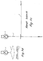
- Figure 1c shows a prior art bag 1 lying flat on top of a stack and a bag 1' lifted from the pile by a gripper 17. After having been lifted the bag 1' hangs down from the gripper as shown in broken dash and dot outlines. In this stretched state the bag has a big moment of inertia and is inclined to become displaced in the gripper, when the gripper makes rapid movements.
- Figure 1d shows a similar lifting of the bag 1 according to the invention.
- the gripper 17 has lifted one bag 1' from the stack, but is not only gripping the first end panel which is provided with the valve opening 4 but also the other end panel.
- the moment of inertia of the bag hanging down is reduced, and also the height of lift necessary to free the bag from the stack is reduced.
- the bags are preferably folded by the method illustrated in Figures 2a-2g.
- the valve bag 1 is delivered from the machine, on which it has been manufactured, in a flat state as shown in Figure 2a. With its end panels facing downwards, it is conveyed through a number of grooved wheels and bevel edged counterwheels A, B, C and A', B', C', being paired so that each pair comprises a wheel with a bevel edge and a wheel with a groove in its circumference.
- the bag When the bag is conveyed between the wheels they make a groove marking in the bag defining the fold line and making it possible to obtain an exact and sharp folding.
- the pairs of grooved wheels A, A' and C, C' are placed in such a way that a marking of the foldings 6, 6' and 7, 7' is obtained as shown in Figure 1a.
- a short distance from the pairs of wheels C, C' the wheels 13, 13' are placed arranged to make a marking opposite the marking made by the wheels C, C'.
- the bag is carried by a conveyor along a set of folding irons shaped as guideways and placed along the conveyor, by means of which folding irons the ends of the bag are folded upwards and the portion between the two opposed markings folded downwards at a substantially right angle to the central portion 2 as shown in Figure 2c.
- the bag is conveyed through a set of pressing wheels D, D' rotating about vertical axles.
- the object of the double marking and the vertical axle pressing wheels is to prevent the end panels from being squeezed between the wheels, which would otherwise lead to an uneven pressing and a risk of squeezing out some of the still uncured adhesive in the bottoms of the bag.
- the ends of the bag are folded downwards as shown in Figure 2e, and the folds are pressed between a further set of pressing wheels E, E' as shown in Figure 2f, whereby the two last folds are made.
- the bag is then placed on top of a stack as shown in Figure 2g. This stack is stable, as the foldings are symmetrical and as the bag has substantially the same number of layers over the whole folded area.
- the applicator according to Figure 3-5 uses the bags folded in accordance with the invention.
- the elevator 11 is arranged to keep the upper surface of the bag on top of the stack at a constant level.
- the bags are all orientated in the same way with the filling opening 4 upwards and to the same side.
- Pressing against the first end panel 3 and just in front of it is a bill-shaped mandrel 14 with circular cross-section, which mandrel is movable in axial direction to a position 14' by means of a pneumatic cylinder.
- the mandrel In the movement from the position designated by 14 to the position designated 14', the mandrel will enter into the valve opening 4 on account of the bill-shaped lip urging the valve opening 4 to open. Then the mandrel and the cylinder 14 are moved upwards to a position 14", 15" just below a gripper with two jaws 17 provided with two lips 18 serving to hold below the valve of the bag being lifted by the lifting of the mandrel to position 14".
- the jaws are curved in order not to clamp the valve around the mandrel, which may be retracted to a position 14"' before the mandrel and the cylinder return to their starting position.
- the lifting of the mandrel and the drive cylinder is performed by means of a lifting cylinder 19.
- the gripper is carried in a rail-arrangement enabling the gripper, which holds the bag with the valve open, to move to a free filling spout on a filling apparatus, where the open valve is clamped by means of suitable holding means during the filling of the bag.
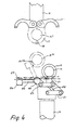
- FIG 4 the mandrel 14 is seen in a front view.
- the placing of the upper valve bag in the stack 12 is indicated by means of dash-and-dot lines.
- the drive cylinder 15 is carried by the lifting cylinder by means of a pair of arms 21 arranged as a parallellogram.
- a swing cylinder 22 the drive cylinder and the mandrel 14 may be swung to a position 14"' around an axis which is substantially on line with the centreline 8 ( Figure 1b) of the bag.
- the centreline 8 Figure 1b
- a gear is placed meshing with a gear 24 on a lifting arm 25.
- a finger 27 is mounted, which finger 27 is movable by means of a cylinder 26. In its starting position the finger is lightly pressing downwards the free corner 9 ( Figure 1b) of the bag in the same side as the filling valve, but at the opposite end. When activated, the cylinder 26 will move the finger forward under the end panel of the bag.
- the finger will lift the second end panel when the swing cylinder is activated in order to swing the mandrel 14 and the drive cylinder 15 to position 14"" and 15"", respectively, and thereby the finger 27 will lift the second end panel which turns about the fold 7' close to the centreline 8 ( Figure 1b), this fold serving as a hinge.
- This lifting will not affect the other part of the bag.
- the lifting cylinder 19 When the lifting cylinder 19 is activated, the mandrel 14 moves to position 14" bringing the second end panel along by means of the finger 27.
- the gripper 16 closes around the bag on the mandrel at 14" the second end panel of the bag will also be gripped.
- the bag hangs in a U-shape from the gripper 17 suspended from the two end panels 3, 5. Owing to the smaller weight hanging down the gripper and especially to the small moment inertia, the risk of a displacement of the bag between the lips 18 of the jaws is eliminated, even though the gripper 16 moves quickly to the filling s
- the mandrel may be retracted to position 14"'.
- the finger is returned to its starting position and by lowering the mandrel and the drive cylinder, the mandrel and the finger return to their starting position, as shown in Figure 5, which shows the arrangement of Figure 3, seen from above. In this position the mandrel and the finger press against the upper bag in the stack.
- Figure 5 the placing of the mandrel 14 in front of the valve is shown and also the finger on the corner 9.
Landscapes
- Engineering & Computer Science (AREA)
- Mechanical Engineering (AREA)
- Making Paper Articles (AREA)
- Bag Frames (AREA)
- Containers And Plastic Fillers For Packaging (AREA)
- Medicines Containing Antibodies Or Antigens For Use As Internal Diagnostic Agents (AREA)
Claims (4)
Priority Applications (1)
| Application Number | Priority Date | Filing Date | Title |
|---|---|---|---|
| AT83302568T ATE24693T1 (de) | 1982-05-10 | 1983-05-06 | Ventilbeutel, herstellungsmethode dafuer und verwendung dieser beutel in fuellvorrichtungen. |
Applications Claiming Priority (2)
| Application Number | Priority Date | Filing Date | Title |
|---|---|---|---|
| DK2085/82 | 1982-05-10 | ||
| DK208582A DK148742C (da) | 1982-05-10 | 1982-05-10 | Ventilsaek og fremgangsmaade ved fremstilling af saekken samt apparat til paasaetning af saekken paa en fyldemaskine |
Publications (3)
| Publication Number | Publication Date |
|---|---|
| EP0097420A2 EP0097420A2 (fr) | 1984-01-04 |
| EP0097420A3 EP0097420A3 (en) | 1984-09-05 |
| EP0097420B1 true EP0097420B1 (fr) | 1987-01-07 |
Family
ID=8109976
Family Applications (1)
| Application Number | Title | Priority Date | Filing Date |
|---|---|---|---|
| EP83302568A Expired EP0097420B1 (fr) | 1982-05-10 | 1983-05-06 | Sac à valve, méthode pour sa fabrication et applicateur pour l'utilisation de ces sacs à valve dans des appareils de remplissage |
Country Status (7)
| Country | Link |
|---|---|
| US (1) | US4618993A (fr) |
| EP (1) | EP0097420B1 (fr) |
| AT (1) | ATE24693T1 (fr) |
| BR (1) | BR8302382A (fr) |
| DE (1) | DE3368900D1 (fr) |
| DK (1) | DK148742C (fr) |
| FI (2) | FI75132C (fr) |
Families Citing this family (2)
| Publication number | Priority date | Publication date | Assignee | Title |
|---|---|---|---|---|
| DK172472B1 (da) * | 1994-07-05 | 1998-09-07 | Bates Ventil Saekke Co As | Fremgangsmåde og apparat til flytning af en ventilsæk fra en fyldeposition til en lukkeposition samt fyldetud hertil |
| US20070289662A1 (en) * | 2005-09-22 | 2007-12-20 | Dematteis Robert B | Filling system |
Family Cites Families (4)
| Publication number | Priority date | Publication date | Assignee | Title |
|---|---|---|---|---|
| SE307499B (fr) * | 1967-06-13 | 1969-01-07 | Hansson S & Co Ab | |
| DE2250678A1 (de) * | 1972-10-16 | 1974-04-25 | Borghart Maschinen Und Geraete | Verfahren zum mechanischen aufstecken von saecken, insbesondere von ventilbodensaecken auf den stutzen von fuellmaschinen und maschine zur durchfuehrung des verfahrens |
| DE2504801C3 (de) * | 1975-02-05 | 1978-03-30 | Windmoeller & Hoelscher, 4540 Lengerich | Stapelfähiger flachliegender und um mindestens zwei Querfalten gefalteter Beutel oder Sack |
| DK143978C (da) * | 1979-06-25 | 1982-04-19 | Bates Ventilsaekke | Fremgangsmaade ved stabling af saekke |
-
0
- FI FI831572A patent/FI831572L/fi unknown
-
1982
- 1982-05-10 DK DK208582A patent/DK148742C/da not_active IP Right Cessation
-
1983
- 1983-04-29 US US06/490,018 patent/US4618993A/en not_active Expired - Fee Related
- 1983-05-06 DE DE8383302568T patent/DE3368900D1/de not_active Expired
- 1983-05-06 BR BR8302382A patent/BR8302382A/pt unknown
- 1983-05-06 FI FI831572A patent/FI75132C/fi not_active IP Right Cessation
- 1983-05-06 EP EP83302568A patent/EP0097420B1/fr not_active Expired
- 1983-05-06 AT AT83302568T patent/ATE24693T1/de active
Also Published As
| Publication number | Publication date |
|---|---|
| DK148742B (da) | 1985-09-16 |
| DE3368900D1 (en) | 1987-02-12 |
| FI831572A0 (fi) | 1983-05-06 |
| EP0097420A2 (fr) | 1984-01-04 |
| EP0097420A3 (en) | 1984-09-05 |
| FI75132C (fi) | 1988-05-09 |
| FI75132B (fi) | 1988-01-29 |
| ATE24693T1 (de) | 1987-01-15 |
| DK148742C (da) | 1989-10-09 |
| DK208582A (da) | 1983-11-11 |
| FI831572L (fi) | 1983-11-11 |
| BR8302382A (pt) | 1984-01-10 |
| US4618993A (en) | 1986-10-21 |
Similar Documents
| Publication | Publication Date | Title |
|---|---|---|
| US6128887A (en) | Method for packaging flat articles | |
| US5425565A (en) | Multiple envelope gripping and transfer apparatus and method | |
| US5464316A (en) | Envelope accumulation, batching and compression apparatus and method | |
| US5857954A (en) | Apparatus for manufacturing cross bottom sacks | |
| DE373025T1 (de) | Maschine, vorzugsweise eine schachtelfuellmaschine, zum automatischen einbringen eines artikels, vorzugsweise einer flasche, in eine schachtel. | |
| US3776109A (en) | Folder for large box blanks | |
| JPH10503456A (ja) | シート状生産物のスタックの収集点からの移動装置 | |
| US5819509A (en) | Bag shouldering and deaerating apparatus | |
| GB2079715A (en) | Method of and apparatus for setting up large sized cartons | |
| EP0117537B1 (fr) | Dispositif pour relever les flancs des boîtes d'emballage tubulaires et aplatis | |
| CN113617671B (zh) | 一种智能分拣系统及其分拣装置 | |
| DE10013417C2 (de) | Vorrichtung und zugehöriges Verfahren zum Palettieren von Kartonagen | |
| US3771280A (en) | End folding machine | |
| US4305241A (en) | Method and apparatus for suspending large sacks from the filling funnel of a sack-filling apparatus | |
| CA2490229C (fr) | Procedes et appareil permettant de plier un materiau en feuille | |
| EP0097420A2 (fr) | Sac à valve, méthode pour sa fabrication et applicateur pour l'utilisation de ces sacs à valve dans des appareils de remplissage | |
| EP0528126B1 (fr) | Dispositif pour le rassemblement ou l'empilage de pièces plates sur une table d'empilage | |
| US4442874A (en) | Automatic valve bag placer | |
| US4580391A (en) | Apparatus for infolding laterally protruding wings of a filled sack onto adhesive strips provided on the top of the sack | |
| JPH03102061A (ja) | 支持構造体から折り畳み製品を取り出す装置 | |
| WO2012048838A1 (fr) | Dispositif et procédé pour prélever et transférer des paquets de sacs disposés à plat | |
| EP2772444B1 (fr) | Dispositif de positionnement de couches de séparation et machine pour charger des palettes avec un tel dispositif | |
| US5035199A (en) | Applicator for crease setting composition | |
| DE602006000533T2 (de) | Verfahren und Vorrichtung zum Überziehen von Produkten mit einer schlauchförmigen Hülle | |
| DE2342731B2 (de) | Maschine zum automatischen Füllen von Säcken |
Legal Events
| Date | Code | Title | Description |
|---|---|---|---|
| PUAI | Public reference made under article 153(3) epc to a published international application that has entered the european phase |
Free format text: ORIGINAL CODE: 0009012 |
|
| AK | Designated contracting states |
Designated state(s): AT BE DE FR GB IT SE |
|
| PUAL | Search report despatched |
Free format text: ORIGINAL CODE: 0009013 |
|
| AK | Designated contracting states |
Designated state(s): AT BE DE FR GB IT SE |
|
| 17P | Request for examination filed |
Effective date: 19850228 |
|
| RAP1 | Party data changed (applicant data changed or rights of an application transferred) |
Owner name: DAC-EMBALLAGE A.M.B.A. |
|
| RIN1 | Information on inventor provided before grant (corrected) |
Inventor name: BERTHELSEN, ERNST RICHARD |
|
| GRAA | (expected) grant |
Free format text: ORIGINAL CODE: 0009210 |
|
| AK | Designated contracting states |
Kind code of ref document: B1 Designated state(s): AT BE DE FR GB IT SE |
|
| PG25 | Lapsed in a contracting state [announced via postgrant information from national office to epo] |
Ref country code: IT Free format text: LAPSE BECAUSE OF FAILURE TO SUBMIT A TRANSLATION OF THE DESCRIPTION OR TO PAY THE FEE WITHIN THE PRESCRIBED TIME-LIMIT;WARNING: LAPSES OF ITALIAN PATENTS WITH EFFECTIVE DATE BEFORE 2007 MAY HAVE OCCURRED AT ANY TIME BEFORE 2007. THE CORRECT EFFECTIVE DATE MAY BE DIFFERENT FROM THE ONE RECORDED. Effective date: 19870107 Ref country code: FR Free format text: THE PATENT HAS BEEN ANNULLED BY A DECISION OF A NATIONAL AUTHORITY Effective date: 19870107 Ref country code: BE Effective date: 19870107 Ref country code: AT Effective date: 19870107 |
|
| REF | Corresponds to: |
Ref document number: 24693 Country of ref document: AT Date of ref document: 19870115 Kind code of ref document: T |
|
| REF | Corresponds to: |
Ref document number: 3368900 Country of ref document: DE Date of ref document: 19870212 |
|
| EN | Fr: translation not filed | ||
| PLBI | Opposition filed |
Free format text: ORIGINAL CODE: 0009260 |
|
| 26 | Opposition filed |
Opponent name: BATES VENTILSAEKKE CO. A/S Effective date: 19871007 |
|
| PG25 | Lapsed in a contracting state [announced via postgrant information from national office to epo] |
Ref country code: GB Effective date: 19880506 |
|
| GBPC | Gb: european patent ceased through non-payment of renewal fee | ||
| PLBN | Opposition rejected |
Free format text: ORIGINAL CODE: 0009273 |
|
| STAA | Information on the status of an ep patent application or granted ep patent |
Free format text: STATUS: OPPOSITION REJECTED |
|
| 27O | Opposition rejected |
Effective date: 19900320 |
|
| PGFP | Annual fee paid to national office [announced via postgrant information from national office to epo] |
Ref country code: DE Payment date: 19930729 Year of fee payment: 11 |
|
| PGFP | Annual fee paid to national office [announced via postgrant information from national office to epo] |
Ref country code: SE Payment date: 19940509 Year of fee payment: 12 |
|
| EAL | Se: european patent in force in sweden |
Ref document number: 83302568.7 |
|
| PG25 | Lapsed in a contracting state [announced via postgrant information from national office to epo] |
Ref country code: DE Effective date: 19950201 |
|
| PG25 | Lapsed in a contracting state [announced via postgrant information from national office to epo] |
Ref country code: SE Effective date: 19950507 |
|
| EUG | Se: european patent has lapsed |
Ref document number: 83302568.7 |
|
| APAH | Appeal reference modified |
Free format text: ORIGINAL CODE: EPIDOSCREFNO |