EP0097549B1 - Anordnung um die Abdichtung eines Tauchmotors zu realisieren und sich darauf beziehender Motor - Google Patents
Anordnung um die Abdichtung eines Tauchmotors zu realisieren und sich darauf beziehender Motor Download PDFInfo
- Publication number
- EP0097549B1 EP0097549B1 EP83401074A EP83401074A EP0097549B1 EP 0097549 B1 EP0097549 B1 EP 0097549B1 EP 83401074 A EP83401074 A EP 83401074A EP 83401074 A EP83401074 A EP 83401074A EP 0097549 B1 EP0097549 B1 EP 0097549B1
- Authority
- EP
- European Patent Office
- Prior art keywords
- shaft
- motor
- casing
- circuit
- accordance
- Prior art date
- Legal status (The legal status is an assumption and is not a legal conclusion. Google has not performed a legal analysis and makes no representation as to the accuracy of the status listed.)
- Expired
Links
- 238000007789 sealing Methods 0.000 title claims description 7
- 230000002093 peripheral effect Effects 0.000 claims description 13
- 239000007788 liquid Substances 0.000 claims description 10
- 238000001816 cooling Methods 0.000 claims description 8
- 230000001681 protective effect Effects 0.000 claims description 7
- 238000005086 pumping Methods 0.000 claims description 6
- 238000005461 lubrication Methods 0.000 claims description 4
- 238000004891 communication Methods 0.000 claims description 2
- 230000000694 effects Effects 0.000 description 7
- 239000012535 impurity Substances 0.000 description 4
- 239000012530 fluid Substances 0.000 description 2
- 239000012528 membrane Substances 0.000 description 2
- 230000004888 barrier function Effects 0.000 description 1
- 239000000110 cooling liquid Substances 0.000 description 1
- 230000007797 corrosion Effects 0.000 description 1
- 238000005260 corrosion Methods 0.000 description 1
- 230000006378 damage Effects 0.000 description 1
- 238000011010 flushing procedure Methods 0.000 description 1
- 238000007654 immersion Methods 0.000 description 1
- 229910052500 inorganic mineral Inorganic materials 0.000 description 1
- 230000001050 lubricating effect Effects 0.000 description 1
- 239000011707 mineral Substances 0.000 description 1
- 230000010355 oscillation Effects 0.000 description 1
- 238000012856 packing Methods 0.000 description 1
- 239000002245 particle Substances 0.000 description 1
- 230000035515 penetration Effects 0.000 description 1
- 239000007787 solid Substances 0.000 description 1
- 238000010408 sweeping Methods 0.000 description 1
- 238000004804 winding Methods 0.000 description 1
Images


Classifications
-
- F—MECHANICAL ENGINEERING; LIGHTING; HEATING; WEAPONS; BLASTING
- F04—POSITIVE - DISPLACEMENT MACHINES FOR LIQUIDS; PUMPS FOR LIQUIDS OR ELASTIC FLUIDS
- F04D—NON-POSITIVE-DISPLACEMENT PUMPS
- F04D13/00—Pumping installations or systems
- F04D13/02—Units comprising pumps and their driving means
- F04D13/06—Units comprising pumps and their driving means the pump being electrically driven
- F04D13/0653—Units comprising pumps and their driving means the pump being electrically driven the motor being flooded
-
- F—MECHANICAL ENGINEERING; LIGHTING; HEATING; WEAPONS; BLASTING
- F16—ENGINEERING ELEMENTS AND UNITS; GENERAL MEASURES FOR PRODUCING AND MAINTAINING EFFECTIVE FUNCTIONING OF MACHINES OR INSTALLATIONS; THERMAL INSULATION IN GENERAL
- F16J—PISTONS; CYLINDERS; SEALINGS
- F16J15/00—Sealings
- F16J15/16—Sealings between relatively-moving surfaces
- F16J15/40—Sealings between relatively-moving surfaces by means of fluid
- F16J15/406—Sealings between relatively-moving surfaces by means of fluid by at least one pump
-
- H—ELECTRICITY
- H02—GENERATION; CONVERSION OR DISTRIBUTION OF ELECTRIC POWER
- H02K—DYNAMO-ELECTRIC MACHINES
- H02K5/00—Casings; Enclosures; Supports
- H02K5/04—Casings or enclosures characterised by the shape, form or construction thereof
- H02K5/12—Casings or enclosures characterised by the shape, form or construction thereof specially adapted for operating in liquid or gas
- H02K5/124—Sealing of shafts
-
- H—ELECTRICITY
- H02—GENERATION; CONVERSION OR DISTRIBUTION OF ELECTRIC POWER
- H02K—DYNAMO-ELECTRIC MACHINES
- H02K5/00—Casings; Enclosures; Supports
- H02K5/04—Casings or enclosures characterised by the shape, form or construction thereof
- H02K5/12—Casings or enclosures characterised by the shape, form or construction thereof specially adapted for operating in liquid or gas
- H02K5/132—Submersible electric motors
Definitions
- the present invention relates to a device for sealing a submersible motor.
- the invention also relates to a motor using this device, intended to operate in total and permanent immersion, in particular for driving pumps in drilled wells.
- Such an electric motor is housed in a cylindrical enclosure and generally coupled to an axial pump.
- This enclosure comprises, for the output of the motor shaft, a rotary lining, one part of which is secured to the shaft, the other being secured to the enclosure.
- the enclosure is filled with an oil intended in particular to ensure the lubrication of the motor bearings and the cooling of the windings, and to homogenize the temperature.
- an oil intended in particular to ensure the lubrication of the motor bearings and the cooling of the windings, and to homogenize the temperature.
- the engine may include a reserve of oil contained in a variable-volume tank in contact with the outside environment, so as to achieve "pressure" between the inside and the outside of the enclosure.
- a device for sealing a motor immersed in an external environment comprising an enclosure, a shaft having an outlet end extending through one end of the enclosure, this shaft supporting at least one rotor adapted to cooperate with a stator integral with the enclosure, the enclosure comprising a rotating lining for the outlet end of the shaft, the enclosure being filled with a liquid of lubrication and cooling under pressure and comprising watertight means for maintaining the general pressure in the enclosure at a value substantially equal to that of the external environment, this device comprising a first circuit creating an overpressure in an area adjacent to the rotary lining characterized in which it includes a second circuit to create an additional overpressure in this zone.
- the second overpressure circuit produced, by a small additional pressure difference, a regular regular and significant overpressure relative to the general pressure in the enclosure.
- the realization of a device with two circuits makes it possible to separate the functions of lubrication and internal cooling of the electric motor on the one hand which require a notable flow and on the other hand the function of pressurization of the lining which requires a high overpressure but low flow.
- the effects of turbulence and associated pressure oscillations are reduced to a minimum, causing an increase in leakage to the outside.
- the device comprises a stop disc wedged on the shaft adapted to ensure both the axial positioning of the drive shaft and to form the first and the second circuit by radial channels drilled in the thickness of the tree, a first series of these channels constituting the first circuit, making a coaxial channel communicate with the shaft with a peripheral space in relation to the two circuits, and a second series of channels forming the second circuit and constituting means of circulation of this second circuit.
- This disc fulfilling all three functions is particularly compact and further reduces the longitudinal dimensions of the motor.
- the motor includes means so that the protective liquid circulating in the channels ensures the cooling of the stop disc used as a pumping system.
- This arrangement makes it possible to cool the stop without having to provide an additional circuit, since the oil circulates inside channels formed in this stop; its cooling is thus particularly effective.
- This arrangement makes it possible to eliminate most of the impurities which may surround the exterior of the lining on the one hand by the centrifugal flushing effect which it allows and on the other hand because the leakage of the lining washes the volume between this lining and this protective part.
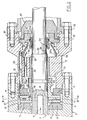
- the motor of the motor-driven pump comprises a shaft 1 carried by a number of bearings 2, on which are fixed a number of rotors 3 cooperating with a stator integral with an enclosure 5.
- the shaft 1 is forced over almost its entire length with an axial channel 6 which opens at the end 7 of the shaft opposite the end 8 which couples to the pump shaft (not shown).
- the shaft 1 Towards its end 8 close to the pump, the shaft 1 carries a disc 9 ( Figures 2 and 3) wedged on it and bearing on shoes 11 of axial stop.
- This disc is housed in a cavity of the enclosure 5 forming around it a peripheral space 12 and it is pierced in its thickness with a first series of radial channels 13 which open on the one hand into this peripheral space and on the other part in an annular recess 14 in relation to radial channels 15 of the shaft 1 opening into the axial channel 6 of this shaft.
- the enclosure 5 being filled with oil, it is understood that, by the centrifugal effect due to the rotation of the disc 9, an oil circulation is established through the stator and the rotors, to the left of FIG. 1 , the return being effected by the axial channel 6, and the peripheral space 12 constituting the high pressure zone of the circuit.
- This first oil circuit is represented by a simple arrow in FIGS. 2 and 3.
- An oil reserve of variable volume in communication with the engine is housed at the bottom of the latter between the enclosure 5 and a flexible annular membrane 16, this membrane being in contact with the external environment, so as to achieve equality of pressure between this external medium and the part of the enclosure furthest from the pump.
- An intermediate part 17 connects the enclosure 5 of the motor to a pump body 18.
- a support ring 19 on which the fixed part 21 has a rotating lining 21 by means of a annular seal 22.
- the movable part 21b of this lining is fixed on the shaft 1 by means of an annular seal 23 and it is applied to the fixed part by means of a spring 24 bearing on a shoulder 25 of the tree.
- the part 17 In the vicinity of the lining, the part 17 has a cavity 26.
- the disc 9 comprises a second series of radial channels 27 formed in its thickness and opening on the one hand into the peripheral space 12 and on the other hand into as many longitudinal channels 28 formed in a sleeve 29 which extends the disc towards the outlet tree.
- the channels 28 open into a cavity 31 of the part 17 which communicates with the cavity 26 by channels 32 in barrel.
- Other channels 33 also in barrel, make the peripheral space 12 communicate with the cavity 26.
- a second oil circuit represented by a double arrow in FIGS. 2 and 3
- oil leaving the space 12 under the effect of the rotation of the disc, reaches the cavity 26 to pass in the vicinity of the lining 21 and return through the channels 32.
- a deflector 34 placed in the cavity 26 forces the oil to pass very close to the cooperation plan of the two parts of the lining.
- This second oil circuit has in common with the first peripheral space 12 where the oil of the two circuits mixes, which provides a cooling effect of the lining.
- the rotation of the disc 9 generates an overpressure in the peripheral space 12, relative to the axial channel 6, itself substantially at the pressure of the ambient medium by the balancing system located at the bottom of the engine.
- This overpressure is transmitted to the cavity 26 through the channels 33.
- the first circuit is produced so that in the vicinity of the lining this overpressure is of the order of bar.
- This very low flow of clean fluid allows operation under optimal conditions several thousand hours without having to reassemble the motor pump for recharging, having regard to the volume of the reserve.
- the weakness of the flow rate also has the advantage of keeping the two parts of the lining apart very little, so that, practically, they never cease to cooperate under the conditions provided.
- the invention thus makes it possible to achieve a leak rate determined in advance and constant throughout the duration of the oil reserve.
- a protective part 35 is wedged on the shaft 1 on the outside of the lining 21 relative to the enclosure 5.
- This part has a peripheral rim 36 which extends to the vicinity of the enclosure.
- this rim closely follows the shape of the support ring 19 oven to form a labyrinth seal constituting a dynamic barrier opposing the possible penetration of impurities in contact with the lining.
- Radial channels 37 are formed in the enclosure 5, opposite the labyrinth seal, for the evacuation of the oil leak.
- oil should be taken to mean any lubricating and / or cooling liquid.
Landscapes
- Engineering & Computer Science (AREA)
- General Engineering & Computer Science (AREA)
- Mechanical Engineering (AREA)
- Power Engineering (AREA)
- Structures Of Non-Positive Displacement Pumps (AREA)
- Sealing Using Fluids, Sealing Without Contact, And Removal Of Oil (AREA)
- Motor Or Generator Frames (AREA)
- Mechanical Sealing (AREA)
- Motor Or Generator Cooling System (AREA)
- Sealing Devices (AREA)
Claims (7)
Applications Claiming Priority (2)
| Application Number | Priority Date | Filing Date | Title |
|---|---|---|---|
| FR8209746A FR2528255B1 (fr) | 1982-06-04 | 1982-06-04 | Procede pour realiser l'etancheite d'un moteur immergeable et moteur s'y rapportant |
| FR8209746 | 1982-06-04 |
Publications (2)
| Publication Number | Publication Date |
|---|---|
| EP0097549A1 EP0097549A1 (de) | 1984-01-04 |
| EP0097549B1 true EP0097549B1 (de) | 1986-08-27 |
Family
ID=9274636
Family Applications (1)
| Application Number | Title | Priority Date | Filing Date |
|---|---|---|---|
| EP83401074A Expired EP0097549B1 (de) | 1982-06-04 | 1983-05-27 | Anordnung um die Abdichtung eines Tauchmotors zu realisieren und sich darauf beziehender Motor |
Country Status (6)
| Country | Link |
|---|---|
| US (1) | US4575315A (de) |
| EP (1) | EP0097549B1 (de) |
| DE (2) | DE97549T1 (de) |
| ES (1) | ES522837A0 (de) |
| FR (1) | FR2528255B1 (de) |
| NO (1) | NO831813L (de) |
Families Citing this family (17)
| Publication number | Priority date | Publication date | Assignee | Title |
|---|---|---|---|---|
| SE436063B (sv) * | 1983-03-24 | 1984-11-05 | Flygt Ab | Anordning for transport av smorjmedel till plantetningar |
| US4768888A (en) * | 1987-04-29 | 1988-09-06 | Mcneil (Ohio) Corporation | Unitary bearing member and motor incorporating the same |
| US5220231A (en) * | 1990-08-23 | 1993-06-15 | Westinghouse Electric Corp. | Integral motor propulsor unit for water vehicles |
| US5220225A (en) * | 1992-06-17 | 1993-06-15 | Vickers, Incorporated | Integrated electric motor driven inline hydraulic apparatus |
| US5765950A (en) * | 1996-11-29 | 1998-06-16 | Goulds Pumps, Incorporated | Thrust bearing assembly |
| US6158967A (en) * | 1998-08-26 | 2000-12-12 | Texas Pressure Systems, Inc. | Barrier fluid seal, reciprocating pump and operating method |
| US6109790A (en) * | 1998-09-30 | 2000-08-29 | Pegasus International, Inc. | Lubricant circulation system for downhole bearing assembly |
| RU2162272C1 (ru) * | 1999-05-31 | 2001-01-20 | Открытое акционерное общество "Борец" | Погружной маслозаполненный электродвигатель |
| US6201327B1 (en) * | 1999-11-17 | 2001-03-13 | Camco International, Inc. | System and method for absorbing the expansion and contraction of internal fluids of a sumergible electric motor |
| US6379127B1 (en) | 2000-09-29 | 2002-04-30 | Lawrence Pumps, Inc. | Submersible motor with shaft seals |
| DE10065587B4 (de) * | 2000-12-28 | 2007-01-18 | B&V Industrietechnik Gmbh | Abdichtungsvorrichtung für rotierende Wellen, insbesondere Stevenrohrabdichtung für Schiffe |
| EP2102507B1 (de) * | 2007-01-19 | 2010-08-18 | Daimler AG | Strömungsarbeitsmaschine |
| CN101499693B (zh) * | 2009-03-19 | 2011-05-11 | 哈尔滨工程大学 | 一种水下机械手用油路内置摆动马达 |
| NO333696B1 (no) | 2010-12-17 | 2013-08-26 | Vetco Gray Scandinavia As | System og fremgangsmate for momentan hydrostatisk drift av hydrodynamiske aksiallagre i en vertikal fluidfortregningsmodul |
| US20150037138A1 (en) * | 2013-07-30 | 2015-02-05 | Hamilton Sundstrand Corporation | Thrust shaft for ram air fan |
| US11480188B2 (en) | 2014-01-05 | 2022-10-25 | Dajustco Ip Holdings Inc. | Integrated pressurized pump shaft seal assembly and method of use thereof |
| JP2017503115A (ja) * | 2014-01-05 | 2017-01-26 | ヴァン−ド−ヴェルド, ピーター フランシスVAN−DE−VELDE, Peter Francis | 一体型加圧ポンプシャフトシール組立体及びその使用方法 |
Family Cites Families (11)
| Publication number | Priority date | Publication date | Assignee | Title |
|---|---|---|---|---|
| US2002915A (en) * | 1932-09-26 | 1935-05-28 | Menhorn Inc | Motor construction |
| US2002916A (en) * | 1934-04-16 | 1935-05-28 | Menborn Inc | Submersible motor construction |
| US2363419A (en) * | 1941-05-05 | 1944-11-21 | Howard Giles Philip Eliot | Submersible pump |
| US2568548A (en) * | 1945-02-20 | 1951-09-18 | Howard Giles Philip Eliot | Electric motor pump of the submersible type |
| US2783400A (en) * | 1955-08-05 | 1957-02-26 | Reda Pump Company | Protecting unit for oil-filled submergible electric motors |
| US2790916A (en) * | 1955-11-14 | 1957-04-30 | Gen Electric | Expansion unit for liquid-filled submersible motors |
| US3075469A (en) * | 1961-01-03 | 1963-01-29 | Red Jacket Mfg Co | Motor construction |
| US3242360A (en) * | 1961-02-09 | 1966-03-22 | Borg Warner | Submersible motor with plural cooling paths |
| FR1432842A (fr) * | 1964-05-21 | 1966-03-25 | Franklin Electric Co Inc | Joint d'assemblage pour moteurs et similaires |
| US3671786A (en) * | 1970-07-06 | 1972-06-20 | Borg Warner | Motor and seal section utilizing a fluorinated ether as a single, homogenous, blocking cooling and lubricating fluid |
| US3688140A (en) * | 1970-09-18 | 1972-08-29 | Franklin Electric Co Inc | Leakage control means for a submersible motor assembly |
-
1982
- 1982-06-04 FR FR8209746A patent/FR2528255B1/fr not_active Expired
-
1983
- 1983-05-20 NO NO831813A patent/NO831813L/no unknown
- 1983-05-27 EP EP83401074A patent/EP0097549B1/de not_active Expired
- 1983-05-27 DE DE198383401074T patent/DE97549T1/de active Pending
- 1983-05-27 DE DE8383401074T patent/DE3365622D1/de not_active Expired
- 1983-05-31 ES ES522837A patent/ES522837A0/es active Granted
- 1983-06-01 US US06/500,178 patent/US4575315A/en not_active Expired - Fee Related
Also Published As
| Publication number | Publication date |
|---|---|
| FR2528255B1 (fr) | 1985-12-20 |
| DE3365622D1 (en) | 1986-10-02 |
| DE97549T1 (de) | 1984-04-12 |
| US4575315A (en) | 1986-03-11 |
| EP0097549A1 (de) | 1984-01-04 |
| NO831813L (no) | 1983-12-05 |
| ES8406813A1 (es) | 1984-07-01 |
| FR2528255A1 (fr) | 1983-12-09 |
| ES522837A0 (es) | 1984-07-01 |
Similar Documents
| Publication | Publication Date | Title |
|---|---|---|
| EP0097549A1 (de) | Anordnung um die Abdichtung eines Tauchmotors zu realisieren und sich darauf beziehender Motor | |
| EP1306560B1 (de) | Elektrohydraulischer Stellantrieb | |
| CN112771279B (zh) | 具有密封装置的滑动轴承和具有滑动轴承的水泵 | |
| FR2503310A1 (fr) | Garniture annulaire d'etancheite a grand diametre et son utilisation | |
| EP2402613B1 (de) | Trockenvakuumpumpe | |
| EP4336713A2 (de) | Vakuumpumpsystem mit ölgeschmierter vakuumpumpe | |
| FR2914384A1 (fr) | Double joint a levre pressurise. | |
| CA3091871C (fr) | Turbopropulseur comprenant une generatrice d'electricite integree | |
| FR2548752A1 (fr) | Joint liquide pour gaz avec balayage de fluide | |
| FR3057029A1 (fr) | Turbopropulseur comprenant une generatrice d'electricite integree | |
| FR2565295A1 (fr) | Pompe a vide rotative etanchee dans l'huile | |
| EP0097548B1 (de) | Bohrlochpumpe und Verfahren zu ihrem Schutz | |
| EP1769175B1 (de) | Dichtungsvorrichtung für eine rotationsmaschine | |
| JPS622149B2 (de) | ||
| FR2588635A1 (fr) | Support d'arbre a palier etanche | |
| WO1981002184A1 (fr) | Dispositif de securite pour pompe | |
| FR2697598A1 (fr) | Dispositif de protection contre l'entrée de particules et de polluants solides. | |
| FR3069571B1 (fr) | Systeme a compression de film fluide et machine tournante comprenant un tel systeme | |
| FR2656902A1 (fr) | Dispositif d'etancheite pour pompe, en particulier pour pompe a eau de circuit de refroidissement. | |
| US11788542B2 (en) | Tandem seal pump | |
| FR2533976A1 (fr) | Motopompe a moteur elecrique a rotor noye | |
| JP2821989B2 (ja) | 軸封装置 | |
| BE1000978A5 (fr) | Motopompe integree a moteur electrique et pompe rotative. | |
| FR3030648A1 (fr) | Compresseur avec systeme d’etancheite | |
| WO2024227580A1 (fr) | Ensemble de pompage de fluide dans un compartiment interne de turbomachine |
Legal Events
| Date | Code | Title | Description |
|---|---|---|---|
| PUAI | Public reference made under article 153(3) epc to a published international application that has entered the european phase |
Free format text: ORIGINAL CODE: 0009012 |
|
| 17P | Request for examination filed |
Effective date: 19830601 |
|
| AK | Designated contracting states |
Designated state(s): DE GB IT NL |
|
| ITCL | It: translation for ep claims filed |
Representative=s name: BARZANO' E ZANARDO ROMA S.P.A. |
|
| TCNL | Nl: translation of patent claims filed | ||
| DET | De: translation of patent claims | ||
| GRAA | (expected) grant |
Free format text: ORIGINAL CODE: 0009210 |
|
| AK | Designated contracting states |
Kind code of ref document: B1 Designated state(s): DE GB IT NL |
|
| REF | Corresponds to: |
Ref document number: 3365622 Country of ref document: DE Date of ref document: 19861002 |
|
| ITF | It: translation for a ep patent filed | ||
| PLBI | Opposition filed |
Free format text: ORIGINAL CODE: 0009260 |
|
| PGFP | Annual fee paid to national office [announced via postgrant information from national office to epo] |
Ref country code: NL Payment date: 19870531 Year of fee payment: 5 |
|
| 26 | Opposition filed |
Opponent name: KLEIN, SCHANZLIN & BECKER AG Effective date: 19870523 |
|
| NLR1 | Nl: opposition has been filed with the epo |
Opponent name: KLEIN,SCHANZLIN & BECKER AG |
|
| RDAG | Patent revoked |
Free format text: ORIGINAL CODE: 0009271 |
|
| STAA | Information on the status of an ep patent application or granted ep patent |
Free format text: STATUS: PATENT REVOKED |
|
| GBPR | Gb: patent revoked under art. 102 of the ep convention designating the uk as contracting state | ||
| 27W | Patent revoked |
Effective date: 19880507 |
|
| NLR2 | Nl: decision of opposition |