EP0097566A1 - Mechanische Vorrichtung zum wahlweisen Antrieb mindestens zweier Wellen durch eine einzige Antriebswelle, vorzugsweise zum Farbbandtransport eines Druckers - Google Patents
Mechanische Vorrichtung zum wahlweisen Antrieb mindestens zweier Wellen durch eine einzige Antriebswelle, vorzugsweise zum Farbbandtransport eines Druckers Download PDFInfo
- Publication number
- EP0097566A1 EP0097566A1 EP83401160A EP83401160A EP0097566A1 EP 0097566 A1 EP0097566 A1 EP 0097566A1 EP 83401160 A EP83401160 A EP 83401160A EP 83401160 A EP83401160 A EP 83401160A EP 0097566 A1 EP0097566 A1 EP 0097566A1
- Authority
- EP
- European Patent Office
- Prior art keywords
- wheel
- driven
- satellite
- driving
- wheels
- Prior art date
- Legal status (The legal status is an assumption and is not a legal conclusion. Google has not performed a legal analysis and makes no representation as to the accuracy of the status listed.)
- Granted
Links
- 238000000034 method Methods 0.000 claims abstract description 4
- 238000005096 rolling process Methods 0.000 claims abstract description 3
- 230000005489 elastic deformation Effects 0.000 claims description 7
- 239000000463 material Substances 0.000 claims description 4
- 230000008569 process Effects 0.000 claims description 2
- 238000004804 winding Methods 0.000 claims description 2
- 238000006243 chemical reaction Methods 0.000 description 4
- 230000000903 blocking effect Effects 0.000 description 2
- 238000006073 displacement reaction Methods 0.000 description 2
- 229920001971 elastomer Polymers 0.000 description 2
- 238000004519 manufacturing process Methods 0.000 description 2
- 238000000465 moulding Methods 0.000 description 2
- 239000000243 solution Substances 0.000 description 2
- 229920000297 Rayon Polymers 0.000 description 1
- 230000009471 action Effects 0.000 description 1
- YFXPPSKYMBTNAV-UHFFFAOYSA-N bensultap Chemical compound C=1C=CC=CC=1S(=O)(=O)SCC(N(C)C)CSS(=O)(=O)C1=CC=CC=C1 YFXPPSKYMBTNAV-UHFFFAOYSA-N 0.000 description 1
- 230000005540 biological transmission Effects 0.000 description 1
- 239000000806 elastomer Substances 0.000 description 1
- 238000001746 injection moulding Methods 0.000 description 1
- 239000004033 plastic Substances 0.000 description 1
- 229920003023 plastic Polymers 0.000 description 1
- 229920002635 polyurethane Polymers 0.000 description 1
- 239000004814 polyurethane Substances 0.000 description 1
- 239000002964 rayon Substances 0.000 description 1
- 230000004044 response Effects 0.000 description 1
- 229920002994 synthetic fiber Polymers 0.000 description 1
Images


Classifications
-
- B—PERFORMING OPERATIONS; TRANSPORTING
- B41—PRINTING; LINING MACHINES; TYPEWRITERS; STAMPS
- B41J—TYPEWRITERS; SELECTIVE PRINTING MECHANISMS, i.e. MECHANISMS PRINTING OTHERWISE THAN FROM A FORME; CORRECTION OF TYPOGRAPHICAL ERRORS
- B41J33/00—Apparatus or arrangements for feeding ink ribbons or like character-size impression-transfer material
- B41J33/14—Ribbon-feed devices or mechanisms
- B41J33/40—Ribbon-feed devices or mechanisms with arrangements for reversing the feed direction
- B41J33/44—Ribbon-feed devices or mechanisms with arrangements for reversing the feed direction automatically
- B41J33/51—Ribbon-feed devices or mechanisms with arrangements for reversing the feed direction automatically and characterised by the use of particular reversing control means
- B41J33/516—Ribbon-feed devices or mechanisms with arrangements for reversing the feed direction automatically and characterised by the use of particular reversing control means using a reversing-feeler responsive to the tension of the ribbon
Definitions
- Devices of the type under consideration find a particularly interesting, but not exclusive, application for longitudinally moving an enoror ribbon in a printing machine such as for example a typewriter, teletype, computer printer, etc.
- the driving wheel and the satellite wheel associated therewith are carried by an independent support capable of moving elastically transversely with respect to the driven wheels.
- the transverse displacement of the support occurs during an increase in the resistive torque produced by the driven wheel (for example end of the ink ribbon or blocking of the ribbon) and the satellite wheel can then be released from the driven wheel with which it previously cooperated.
- the transverse movement of the support does not allow the drive of the driving shaft to be carried out by a conventional cable system and it is necessary to provide a specific geared motor.
- the object of the invention is essentially to remedy the drawbacks explained above and to produce a compact, light device comprising few parts, reliable, able to be driven by cables in a conventional manner, and inexpensive so that it can be incorporated into widely distributed printing machines at relatively low cost.
- the torque of the driving and satellite wheels can be housed in the free space separating the two driven wheels, the axis of the driving wheel being able for example to be aligned with the two shafts of the driven wheels.
- the mechanical structure thus formed is relatively compact, with no cantilevered parts or members, comprises a minimum number of component parts and is therefore of minimum weight and inertia compatible with the requirements required for certain applications such as equipment of a printer machine cart.
- each driven wheel comprises a rigid or substantially rigid rim and hub joined to one another by radially deformable elastically connecting means.
- the connecting means comprise several springs arranged radially and angularly equidistant from each other, these springs being able to be, for example, helical springs or alternatively longitudinally interposable spokes.
- connection means advantageously comprise a continuous annular web, interposed between hub and rim, made of a material having elastic deformation properties at least in radial directions.
- the wheel as well made up can be easily manufactured in one piece by using synthetic molding techniques.
- the driving, satellite and driven wheels are toothed wheels and / or friction wheels.
- a particularly preferred, although not exclusive, application of the mechanical drive device of the invention resides in a device for longitudinally moving an ink ribbon of a printing machine such as a typewriter, teletype, computer printer, etc. , the two driven wheels then cooperating respectively in rotation with two support plates for the reels for winding the ink ribbon.
- this device is placed on the mobile carriage of the printing machine and that the driving shaft cooperates with cable drive means known per se, comprising two free wheels mounted on the drive shaft and two parallel drive cables coiled respectively around the two freewheels.
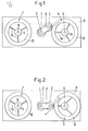
- a driving shaft 1 drives a driving wheel 2: for example, as shown, the wheel 2 is wedged on the shaft 1.
- a satellite wheel 3 cooperates permanently with the driving wheel 2 and is continuously driven by it; the wheel 3 is mounted idly on a support 4 (constituted for example by two lateral flanges) which can rotate freely around the axis of the driving wheel 2.
- first driven wheel 5 integral in rotation with a first driven shaft 6 (the wheel 5 can for example be wedged on the shaft 6) and with which the satellite wheel 3 can come into engagement.
- a second driven wheel 7 is integral in rotation with a second driven shaft 8 (for example by being wedged on the shaft 8) and the satellite wheel 3 can come into engagement with the second driven wheel 7.
- the axes of the driving wheel 2, the satellite wheel 3 and the two driven wheels 5 and 7 are mutually parallel and substantially perpendicular to a support plate. 9, all the wheels being substantially coplanar.
- the two driven wheels 5, 7 are arranged equally distance from the axis of the driving wheel 2, this distance being less than the sum of the diameter of the satellite wheel 3 and the radius of the driving wheel 2.
- the two driven wheels 5 and 7 are arranged to be able to undergo local radial elastic deformations; that is, they are arranged so that their respective axes are stationary but that the pe - riphérie can deform or move radially locally.
- each wheel 5, 7 comprises a rigid hub respectively 10, 11, a rigid or substantially rigid rim respectively 12, 13, and connecting means respectively 14, 15 interposed between the rim and the hub, these connecting means being suitable to undergo radial elastic deformations.
- the elastic means 14, 15 may for example be constituted by radial helical springs, in particular three springs arranged at 120 ° as shown. It can also be springs constituted by masses of elastomer. It can also be bent spokes curable longitudinally.
- the connecting means 14, 15 consist of a continuous web made of a material strong enough to ensure the mechanical connection of the rim 12, 13 to the hub 10, 11, but simultaneously having elastic deformation properties at least in radial directions.
- the wheel can be manufactured by double injection molding, the web being made of rubber, polyurethane, etc., and the hub and rim made of plastic.
- connection means are constituted by the above mentioned raises or by a confined veil.
- the wheels used can be either. all types suitable for the proper transmission of torques. They may be toothed wheels, wheels with a smooth surface having a high coefficient of friction, wheels with a grooved surface or any combination of such wheels.
- the driving shaft 1 drives the driving wheel 2 for example in the dextrorotatory direction and itself drives the satellite wheel 3 in the senestrogyret direction
- the support 4 tends to rotate in the dextrorotatory direction around the axis of the wheel 2 on which it is articulated and therefore, in normal operation, the satellite wheel 3 remains applied in engagement against the driven wheel 5.
- the reaction force maintaining the satellite wheel 3 applied against the driven wheel 5 is less than the radial deformation force of the means 14, it follows that the device is in the stable position shown in FIG. 1, the wheel 5 being driven in the dextrorotatory direction.
- the reaction torque which keeps the satellite wheel 3 in abutment against the driven wheel 5 increases and, when the force thus generated becomes greater than the radial elastic force of the connection means 14, the satellite wheel 3 pushes the rim 12 of the driven wheel 5 towards the hub 10 against the radial elastic forces exerted by the connection means 14.
- the hub 10 retains the same axis of rotation (in this case, it remains wedged on the driven shaft 6), but the rim 12 is off-center ( Figure 2).
- the device of the invention is likely to find many applications among which we will note more particularly that relating to the training of ink ribbons in printing machines such as typewriters, teletypes, computer printers, etc.
- Such an application is shown diagrammatically in FIGS. 4 to 6 to which reference is now made (and on which the elements identical to those of FIGS. 1 to 3 are designated by the same reference numerals).
- Brakes 25, cooperating respectively with the driven wheels 5 and 7, ensure constant tensioning of the ribbon 20 (see FIG. 4).
- the two coils 19 and 22 are selectively driven by the satellite wheel 3, in the direct direction (arrow 23) in the case of a normal drive (wheel-3 shown in solid lines) or in the opposite direction (arrow 24) if the ribbon is prevented from moving in the normal direction (wheel 3 shown in phantom).
- This assembly automatically reverses the direction of scrolling of the ribbon, for example at the end of the ribbon or in the event of the ribbon jamming in the normal direction (arrow 23).
- the satellite wheel 3 turns alone around the shaft 1 without driving the driven wheels 5 and 7.
- the assembly shown in Figures 4 to 6 is particularly interesting in that it can be installed easily, due to its compactness, on a carriage of the printing machine.
- a motor device such as a gear motor, independent; one can carry out the drive of the driving shaft 1 using a conventional drive by double cable and double freewheel, which is commonly used in printing machines.
Landscapes
- Impression-Transfer Materials And Handling Thereof (AREA)
- Transmission Devices (AREA)
Applications Claiming Priority (2)
| Application Number | Priority Date | Filing Date | Title |
|---|---|---|---|
| FR8210607A FR2528929B1 (fr) | 1982-06-17 | 1982-06-17 | Perfectionnements apportes a des dispositifs mecaniques d'entrainement selectif d'au moins deux arbres menes a partir d'un arbre menant unique, notamment pour le deplacement longitudinal d'un ruban encreur dans une machine imprimante |
| FR8210607 | 1982-06-17 |
Publications (2)
| Publication Number | Publication Date |
|---|---|
| EP0097566A1 true EP0097566A1 (de) | 1984-01-04 |
| EP0097566B1 EP0097566B1 (de) | 1987-06-03 |
Family
ID=9275114
Family Applications (1)
| Application Number | Title | Priority Date | Filing Date |
|---|---|---|---|
| EP19830401160 Expired EP0097566B1 (de) | 1982-06-17 | 1983-06-07 | Mechanische Vorrichtung zum wahlweisen Antrieb mindestens zweier Wellen durch eine einzige Antriebswelle, vorzugsweise zum Farbbandtransport eines Druckers |
Country Status (5)
| Country | Link |
|---|---|
| EP (1) | EP0097566B1 (de) |
| JP (1) | JPS596460A (de) |
| DE (1) | DE3371883D1 (de) |
| FR (1) | FR2528929B1 (de) |
| YU (1) | YU134183A (de) |
Cited By (3)
| Publication number | Priority date | Publication date | Assignee | Title |
|---|---|---|---|---|
| US4850725A (en) * | 1988-06-15 | 1989-07-25 | Ncr Corporation | Unidirectional ribbon drive mechanism |
| US5005999A (en) * | 1988-03-16 | 1991-04-09 | Merlin C.T.C. Production Division Nederland B.V. | Ink cassette with control means for alternately driving one of two spool bearing therein |
| WO2014074780A1 (en) * | 2012-11-12 | 2014-05-15 | Siemens Healthcare Diagnostics Inc. | Single drive mechanism |
Families Citing this family (13)
| Publication number | Priority date | Publication date | Assignee | Title |
|---|---|---|---|---|
| JP5857576B2 (ja) * | 2011-09-21 | 2016-02-10 | アイシン精機株式会社 | 複数出力切替機構 |
| JP7327059B2 (ja) | 2019-09-30 | 2023-08-16 | ブラザー工業株式会社 | 印刷装置及び印刷用カセット |
| JP7322640B2 (ja) | 2019-09-30 | 2023-08-08 | ブラザー工業株式会社 | 印刷用カセット |
| JP7395911B2 (ja) | 2019-09-30 | 2023-12-12 | ブラザー工業株式会社 | 印刷用カセット及び印刷装置 |
| JP7395912B2 (ja) | 2019-09-30 | 2023-12-12 | ブラザー工業株式会社 | 印刷用カセット及び印刷装置 |
| JP7306197B2 (ja) | 2019-09-30 | 2023-07-11 | ブラザー工業株式会社 | 印刷装置及び印刷用カセット |
| JP7347077B2 (ja) | 2019-09-30 | 2023-09-20 | ブラザー工業株式会社 | 印刷用カセット |
| JP7322638B2 (ja) | 2019-09-30 | 2023-08-08 | ブラザー工業株式会社 | 印刷装置及び印刷用カセット |
| JP7604825B2 (ja) | 2020-09-30 | 2024-12-24 | ブラザー工業株式会社 | 印刷用カセット及び印刷装置 |
| JP7625815B2 (ja) | 2020-09-30 | 2025-02-04 | ブラザー工業株式会社 | 補助テープカセット及び印刷用テープカセット |
| JP7651831B2 (ja) | 2020-09-30 | 2025-03-27 | ブラザー工業株式会社 | 補助テープカセット |
| JP7589480B2 (ja) | 2020-09-30 | 2024-11-26 | ブラザー工業株式会社 | 補助テープカセット |
| JP7593152B2 (ja) | 2021-01-29 | 2024-12-03 | ブラザー工業株式会社 | 補助テープカセット、印刷用テープカセット及び印刷用カセット |
Citations (6)
| Publication number | Priority date | Publication date | Assignee | Title |
|---|---|---|---|---|
| DE166065C (de) * | ||||
| US2583385A (en) * | 1947-01-11 | 1952-01-22 | Morse Instr Company | Automatically operated film winding mechanism |
| FR2198586A5 (de) * | 1972-09-01 | 1974-03-29 | Honeywell Inf Systems Italia | |
| US3841459A (en) * | 1971-04-21 | 1974-10-15 | Nixdorf Computer Ag | Movable carriage assembly and ink ribbon control |
| DE2737096A1 (de) * | 1977-08-17 | 1979-03-01 | Siemens Ag | Vorrichtung zur vorschubrichtungsumkehr fuer farbbaender |
| EP0051996A2 (de) * | 1980-11-10 | 1982-05-19 | Wheel Developments Limited | Rad mit federnden Speichen |
-
1982
- 1982-06-17 FR FR8210607A patent/FR2528929B1/fr not_active Expired
-
1983
- 1983-06-07 EP EP19830401160 patent/EP0097566B1/de not_active Expired
- 1983-06-07 DE DE8383401160T patent/DE3371883D1/de not_active Expired
- 1983-06-15 JP JP10759583A patent/JPS596460A/ja active Pending
- 1983-06-17 YU YU134183A patent/YU134183A/xx unknown
Patent Citations (6)
| Publication number | Priority date | Publication date | Assignee | Title |
|---|---|---|---|---|
| DE166065C (de) * | ||||
| US2583385A (en) * | 1947-01-11 | 1952-01-22 | Morse Instr Company | Automatically operated film winding mechanism |
| US3841459A (en) * | 1971-04-21 | 1974-10-15 | Nixdorf Computer Ag | Movable carriage assembly and ink ribbon control |
| FR2198586A5 (de) * | 1972-09-01 | 1974-03-29 | Honeywell Inf Systems Italia | |
| DE2737096A1 (de) * | 1977-08-17 | 1979-03-01 | Siemens Ag | Vorrichtung zur vorschubrichtungsumkehr fuer farbbaender |
| EP0051996A2 (de) * | 1980-11-10 | 1982-05-19 | Wheel Developments Limited | Rad mit federnden Speichen |
Cited By (3)
| Publication number | Priority date | Publication date | Assignee | Title |
|---|---|---|---|---|
| US5005999A (en) * | 1988-03-16 | 1991-04-09 | Merlin C.T.C. Production Division Nederland B.V. | Ink cassette with control means for alternately driving one of two spool bearing therein |
| US4850725A (en) * | 1988-06-15 | 1989-07-25 | Ncr Corporation | Unidirectional ribbon drive mechanism |
| WO2014074780A1 (en) * | 2012-11-12 | 2014-05-15 | Siemens Healthcare Diagnostics Inc. | Single drive mechanism |
Also Published As
| Publication number | Publication date |
|---|---|
| FR2528929B1 (fr) | 1988-04-08 |
| JPS596460A (ja) | 1984-01-13 |
| FR2528929A1 (fr) | 1983-12-23 |
| EP0097566B1 (de) | 1987-06-03 |
| DE3371883D1 (en) | 1987-07-09 |
| YU134183A (en) | 1987-02-28 |
Similar Documents
| Publication | Publication Date | Title |
|---|---|---|
| EP0097566B1 (de) | Mechanische Vorrichtung zum wahlweisen Antrieb mindestens zweier Wellen durch eine einzige Antriebswelle, vorzugsweise zum Farbbandtransport eines Druckers | |
| FR2563203A1 (fr) | Treuil | |
| FR2488667A1 (fr) | Dispositif de changement de vitesse pour bicyclette | |
| CA2190689C (fr) | Rouleau pour convoyeur motorise | |
| FR2549450A1 (fr) | Unite d'entrainement par rouleaux, notamment pour le deplacement d'objets sur une bande convoyeuse | |
| EP1486452A2 (de) | System zum Heben und Stabilisieren von einem hängenden Lastträger | |
| FR2479939A1 (fr) | Engrenages planetaires du type a rouleaux ayant un agencement de prechargement | |
| FR2524682A1 (fr) | Dispositif de changement de mode de fonctionnement pour un appareil d'enregistrement et de reproduction a bande magnetique tel qu'un magnetophone | |
| FR2525112A1 (fr) | Enrouleur pour ceinture de securite pour vehicule automobile | |
| FR2737268A1 (fr) | Ensemble formant disque amortisseur comportant des ressorts a deplacement radial limite | |
| FR2632037A1 (fr) | Transmission a variation continue a courroie plate | |
| FR2703626A1 (fr) | Agencement et procédé pour éliminer les tâches du cylindre porte-plaque dans une presse lithographique. | |
| FR2476256A1 (fr) | Roue de transmission a diametre variable | |
| EP4306745A1 (de) | Stützwagen für ein beckenabdecksystem | |
| EP1521916A1 (de) | Vorrichtung für freilauflager und freilaufscheibe | |
| WO1998048399A1 (fr) | Dispositif d'affichage | |
| FR2545462A1 (fr) | Dispositif d'entrainement de bobines | |
| FR2696660A1 (fr) | Dispositif de transport de produits tels que des fruits dans une machine de calibrage automatique. | |
| FR2571167A1 (fr) | Dispositif d'affichage a deroulement. | |
| FR3066470B1 (fr) | Dispositif de regulation de transmission par chaine | |
| FR2564380A1 (fr) | Dispositif de reduction de chocs dans la commande d'encrage d'un preneur d'encre alternatif de presse offset rotative | |
| EP0466608A1 (de) | Kassette für Band mit Mittel zum Halten von in der Kassette montierten Teilen in einer vorherbestimmten Lage | |
| FR2529158A1 (fr) | Dispositif d'entrainement pour bande sans fin de roulement du type chenille de vehicule | |
| FR2682647A1 (fr) | Dispositif d'entrainement debrayable pour roues non motrices de vehicule automobile. | |
| EP0043334A1 (de) | Einrichtung zum Ein- und Auskuppeln und Bremsen drehgetriebener Elemente |
Legal Events
| Date | Code | Title | Description |
|---|---|---|---|
| PUAI | Public reference made under article 153(3) epc to a published international application that has entered the european phase |
Free format text: ORIGINAL CODE: 0009012 |
|
| AK | Designated contracting states |
Designated state(s): DE GB IT |
|
| 17P | Request for examination filed |
Effective date: 19831219 |
|
| ITF | It: translation for a ep patent filed | ||
| GRAA | (expected) grant |
Free format text: ORIGINAL CODE: 0009210 |
|
| AK | Designated contracting states |
Kind code of ref document: B1 Designated state(s): DE GB IT |
|
| REF | Corresponds to: |
Ref document number: 3371883 Country of ref document: DE Date of ref document: 19870709 |
|
| PLBE | No opposition filed within time limit |
Free format text: ORIGINAL CODE: 0009261 |
|
| STAA | Information on the status of an ep patent application or granted ep patent |
Free format text: STATUS: NO OPPOSITION FILED WITHIN TIME LIMIT |
|
| 26N | No opposition filed | ||
| PGFP | Annual fee paid to national office [announced via postgrant information from national office to epo] |
Ref country code: GB Payment date: 19930601 Year of fee payment: 11 |
|
| PGFP | Annual fee paid to national office [announced via postgrant information from national office to epo] |
Ref country code: DE Payment date: 19930618 Year of fee payment: 11 |
|
| ITTA | It: last paid annual fee | ||
| PG25 | Lapsed in a contracting state [announced via postgrant information from national office to epo] |
Ref country code: GB Effective date: 19940607 |
|
| GBPC | Gb: european patent ceased through non-payment of renewal fee |
Effective date: 19940607 |
|
| PG25 | Lapsed in a contracting state [announced via postgrant information from national office to epo] |
Ref country code: DE Effective date: 19950301 |