EP0097608A2 - Turbinenrad mit in der Peripherie eingearbeiteten Schaufeln - Google Patents
Turbinenrad mit in der Peripherie eingearbeiteten Schaufeln Download PDFInfo
- Publication number
- EP0097608A2 EP0097608A2 EP83630100A EP83630100A EP0097608A2 EP 0097608 A2 EP0097608 A2 EP 0097608A2 EP 83630100 A EP83630100 A EP 83630100A EP 83630100 A EP83630100 A EP 83630100A EP 0097608 A2 EP0097608 A2 EP 0097608A2
- Authority
- EP
- European Patent Office
- Prior art keywords
- buckets
- wheel
- rim portion
- turbine
- leg portions
- Prior art date
- Legal status (The legal status is an assumption and is not a legal conclusion. Google has not performed a legal analysis and makes no representation as to the accuracy of the status listed.)
- Granted
Links
- 239000012530 fluid Substances 0.000 claims abstract description 16
- 239000007787 solid Substances 0.000 claims description 14
- 238000000034 method Methods 0.000 claims description 10
- 238000007789 sealing Methods 0.000 claims description 5
- 238000004519 manufacturing process Methods 0.000 claims description 3
- 230000007704 transition Effects 0.000 claims description 2
- 238000003754 machining Methods 0.000 abstract description 11
- 230000003628 erosive effect Effects 0.000 description 8
- XLYOFNOQVPJJNP-UHFFFAOYSA-N water Substances O XLYOFNOQVPJJNP-UHFFFAOYSA-N 0.000 description 8
- 238000010276 construction Methods 0.000 description 6
- 238000006243 chemical reaction Methods 0.000 description 5
- 230000000694 effects Effects 0.000 description 5
- 239000007789 gas Substances 0.000 description 5
- 239000002245 particle Substances 0.000 description 5
- 230000008569 process Effects 0.000 description 5
- 239000010935 stainless steel Substances 0.000 description 4
- 229910001220 stainless steel Inorganic materials 0.000 description 4
- 238000005266 casting Methods 0.000 description 3
- OKTJSMMVPCPJKN-UHFFFAOYSA-N Carbon Chemical compound [C] OKTJSMMVPCPJKN-UHFFFAOYSA-N 0.000 description 2
- 229910000831 Steel Inorganic materials 0.000 description 2
- 229910052799 carbon Inorganic materials 0.000 description 2
- 239000000463 material Substances 0.000 description 2
- 230000009467 reduction Effects 0.000 description 2
- 239000010959 steel Substances 0.000 description 2
- 229910000975 Carbon steel Inorganic materials 0.000 description 1
- VYZAMTAEIAYCRO-UHFFFAOYSA-N Chromium Chemical compound [Cr] VYZAMTAEIAYCRO-UHFFFAOYSA-N 0.000 description 1
- 229910001060 Gray iron Inorganic materials 0.000 description 1
- 238000010793 Steam injection (oil industry) Methods 0.000 description 1
- 230000000712 assembly Effects 0.000 description 1
- 238000000429 assembly Methods 0.000 description 1
- 238000005219 brazing Methods 0.000 description 1
- 239000010962 carbon steel Substances 0.000 description 1
- 230000008859 change Effects 0.000 description 1
- 239000003795 chemical substances by application Substances 0.000 description 1
- 230000008878 coupling Effects 0.000 description 1
- 238000010168 coupling process Methods 0.000 description 1
- 238000005859 coupling reaction Methods 0.000 description 1
- 230000003247 decreasing effect Effects 0.000 description 1
- 230000001419 dependent effect Effects 0.000 description 1
- RUZYUOTYCVRMRZ-UHFFFAOYSA-N doxazosin Chemical compound C1OC2=CC=CC=C2OC1C(=O)N(CC1)CCN1C1=NC(N)=C(C=C(C(OC)=C2)OC)C2=N1 RUZYUOTYCVRMRZ-UHFFFAOYSA-N 0.000 description 1
- 230000008030 elimination Effects 0.000 description 1
- 238000003379 elimination reaction Methods 0.000 description 1
- 230000002708 enhancing effect Effects 0.000 description 1
- 238000005242 forging Methods 0.000 description 1
- 229910052751 metal Inorganic materials 0.000 description 1
- 239000002184 metal Substances 0.000 description 1
- 229910052750 molybdenum Inorganic materials 0.000 description 1
- 239000011733 molybdenum Substances 0.000 description 1
- 239000003129 oil well Substances 0.000 description 1
- 238000005381 potential energy Methods 0.000 description 1
- 238000011084 recovery Methods 0.000 description 1
- 229920006395 saturated elastomer Polymers 0.000 description 1
- 238000007493 shaping process Methods 0.000 description 1
- 239000000243 solution Substances 0.000 description 1
- 230000003068 static effect Effects 0.000 description 1
- 230000008016 vaporization Effects 0.000 description 1
- 238000009834 vaporization Methods 0.000 description 1
Images



Classifications
-
- F—MECHANICAL ENGINEERING; LIGHTING; HEATING; WEAPONS; BLASTING
- F01—MACHINES OR ENGINES IN GENERAL; ENGINE PLANTS IN GENERAL; STEAM ENGINES
- F01D—NON-POSITIVE DISPLACEMENT MACHINES OR ENGINES, e.g. STEAM TURBINES
- F01D1/00—Non-positive-displacement machines or engines, e.g. steam turbines
- F01D1/02—Non-positive-displacement machines or engines, e.g. steam turbines with stationary working-fluid guiding means and bladed or like rotor, e.g. multi-bladed impulse steam turbines
-
- F—MECHANICAL ENGINEERING; LIGHTING; HEATING; WEAPONS; BLASTING
- F01—MACHINES OR ENGINES IN GENERAL; ENGINE PLANTS IN GENERAL; STEAM ENGINES
- F01D—NON-POSITIVE DISPLACEMENT MACHINES OR ENGINES, e.g. STEAM TURBINES
- F01D1/00—Non-positive-displacement machines or engines, e.g. steam turbines
- F01D1/02—Non-positive-displacement machines or engines, e.g. steam turbines with stationary working-fluid guiding means and bladed or like rotor, e.g. multi-bladed impulse steam turbines
- F01D1/026—Impact turbines with buckets, i.e. impulse turbines, e.g. Pelton turbines
-
- F—MECHANICAL ENGINEERING; LIGHTING; HEATING; WEAPONS; BLASTING
- F05—INDEXING SCHEMES RELATING TO ENGINES OR PUMPS IN VARIOUS SUBCLASSES OF CLASSES F01-F04
- F05D—INDEXING SCHEME FOR ASPECTS RELATING TO NON-POSITIVE-DISPLACEMENT MACHINES OR ENGINES, GAS-TURBINES OR JET-PROPULSION PLANTS
- F05D2250/00—Geometry
- F05D2250/10—Two-dimensional
- F05D2250/19—Two-dimensional machined; miscellaneous
-
- F—MECHANICAL ENGINEERING; LIGHTING; HEATING; WEAPONS; BLASTING
- F05—INDEXING SCHEMES RELATING TO ENGINES OR PUMPS IN VARIOUS SUBCLASSES OF CLASSES F01-F04
- F05D—INDEXING SCHEME FOR ASPECTS RELATING TO NON-POSITIVE-DISPLACEMENT MACHINES OR ENGINES, GAS-TURBINES OR JET-PROPULSION PLANTS
- F05D2250/00—Geometry
- F05D2250/20—Three-dimensional
- F05D2250/29—Three-dimensional machined; miscellaneous
Definitions
- the buckets or blades of turbines are subject to wear or erosion due to a number of factors.
- a steam turbine prime mover for example, the kinetic energy that is absorbed from the steam by the moving blades or buckets and delivered as shaft work to the device being driven results from the expansion of the steam into the heat of vaporization region resulting in a lowering in the quality of the steam.
- the buckets or blades become more susceptible to erosion.
- wet steam is generally associated with the last stages of a condensing steam turbine, energy recovery from process steam and the advent of geothermal power, for example, have resulted in the initial supplying of wet steam, e.g.
- blade erosion is also a function of the velocity and impingement angle of the moisture particles.
- the presence of particulates in gases has a similar effect to the presence of water droplets.
- One solution to blade erosion is the use of replaceable blades. Additionally, for low horsepower, dependent upon steam inlet and exit conditions, conventional axial turbines are inefficient due to partial admission operation.
- the present invention is directed to a turbine of solid wheel construction which is capable of very high tip speeds depending upon the type of design and the material used.
- This turbine is more efficient than a conventional axial flow turbine and is at least as efficient as a radial inflow turbine in the overall sense since it has a much lower RPM and therefore smaller mechanical losses.
- the buckets are machined into the outer diameter of the wheel.
- the nozzle ring construction is of the radial inflow type with converging or expanding nozzles and low incidence angles for maximum performance. Because of the bucket geometry and the tangential inflow from the nozzles, moisture droplets or solid particulates moving slower than the gas flow will impinge upon the buckets at low angles and low relative velocities greatly reducing erosion and minimizing braking losses.
- the inlet and exhaust casings are simply constructed to enable partial to full admission of motive fluid at very high pressures. Since the turbine wheel has buckets machined directly into it, bucket failures are essentially impossible. Furthermore, because of the inherent geometrical configuration of the buckets in relation to the disk, disk/blade induced vibration is virtually eliminated. Integral rotor or through bolt construction may be used. With this rugged construction, the present invention is suitable for a wide range of gases, either superheated or saturated. By using a gear unit, any output shaft speed is obtainable at optimum turbine efficiency.
- a plurality of uniformly spaced buckets are formed in the rim of a solid wheel.
- Each of the buckets has an overlapping relationship with the adjacent buckets in the machining operation such that the wall of each bucket is essentially a portion of the side of a cylinder and defines an essentially semicircular bight with straight extensions or legs on both sides and an island at the center of the cylinder.
- Motive fluid is supplied in a generally tangential direction with respect to the rim of the wheel from points axially spaced from the center of the buckets such that flow is between one side of the wall defining the bight and the island and the fluid is turned through approximately 180° with a transfer of kinetic energy to the wheel and exits from the bucket between the other side of the wall defining the bight and the island.
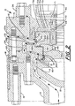
- the numeral 10 generally designates a 2-stage solid wheel turbine including axial inlet casing 12, exhaust volute casing 16, volute cover 18, first stage nozzle ring 20, second stage nozzle assembly 22, 2-stage solid turbine wheel or rotor 26, shaft 28, balance piston seal ring 32, shaft seal ring 34, bearing housing 36 and bearings 38 and 39.
- Labyrinth seal 41 provides a seal between wheel 26 and nozzle ring 20.
- Labyrinth seals 42, 43 and 44 provide a seal between wheel 26 and nozzle assembly 22.
- Labyrinth seal 45 provides a seal between wheel 26 and balance piston seal ring 32.
- Inlet casing 12 is, preferably, a one piece casting, such as chrome stainless steel, and consists of a short, flanged axial inlet pipe adapted to be connected to a source of steam, an inlet cone containing nose cone 13 ana inlet guide vanes 14.
- Inlet casing 12 serves as the connection between the steam source and the turbine 10 and provides support to the nozzle structures 20 and 22 and is in turn supported by exhaust volute casing 16 through volute cover 18.
- Volute cover 18 is shaped as a one piece flanged shell and serves to seal leakage from/to volute casing 16 and to support inlet casing 12 and nozzle structures 20 and 22.
- Exhaust volute casing 16 is, preferably, a scroll or a torus type volute with a tangential discharge and is suitably made as a one piece carbon steel casting. Volute casing 16 serves as a collector for the exhaust steam as well as containing and housing the other turbine components.
- the nozzle structures 20 and 22 are, preferably, stainless steel.
- Nozzle ring 20 is of one piece, solid ring type construction while nozzle assembly 22 is of two piece construction made up of members 22a and b.
- Nozzle blades 21 and 23 are milled integral into the diaphragms defined by members 20 and 22a. The angles and sizes of the nozzle blades 21 and 23 depend upon the design load.
- first stage nozzle ring 20 is of a type providing a generally tangential discharge with respect to the first stage 26a of turbine wheel 26.
- the nozzle blades 21 milled into the ring type steel plate or diaphragm are of the profile-type blades.
- labyrinth seal 41 serves to isolate the bucket inlet from its outlet.
- Nozzle ring 20 is securely attached to the inlet casing 12 so that there is no clearance over the free end of the nozzle blades.
- first stage nozzle ring 20 is attached to the second stage nozzle assembly 22 while it is attached directly to the exhaust volute casing 16 for a single stage turbine.
- the second stage nozzle assembly 22 consists of essentially two parts.
- the first part, 22a is a nozzle ring member.
- the second part, 22b is a diaphragm-like disk member containing labyrinth seal 42 on its inner rim and labyrinth seal 43 on its side facing the seconde stage, 26b, of wheel 26.
- axial-type guide vanes 24 On the outer edge of the diaphragm 22b, there are axial-type guide vanes 24 which may be machined directly onto member 22b, they may be standard stock welded onto member 22b, or they can be cast as an integral part with member 22b, if member 22b is cast.
- the axial guide vanes 24 serve two purposes: the first is to impart tangential momentum to the steam flow; and, the second purpose is to provide mechanical guidance and support to the member 22b in the radial direction.
- the axial guide vanes 24 can be replaced by radial reversing vanes or blades (not illustrated) at the outer diameter of the diaphragm opposite the nozzle ring 20.
- Members 22a and b are assembled together to form an integral second stage nozzle assembly 22.
- Assembly can be by using one stud (not illustrated) through each blade 23 of member 22a, at the point of maximum thickness, which may be followed by brazing to enhance the strength of the overall assembly.
- Both the first stage nozzle ring 20 and the second stage nozzle assembly 22 are supported inside exhaust volute casing 16 in the illustrated embodiment.
- Balance piston seal ring 32 is of a tubular ring form with a diametral split and is used only with multistage machines.
- Labyrinth seal 45 is located on the inner face of seal ring 32.
- Seal ring 32 is bolted to the bearing housing 36 through its thickness.
- Shaft seal ring 34 is illustrated as a stepped labyrinth seal with two intermediate pressure leakoff ports 70 and 71 which break down the stream pressure to slightly below or slightly above atmospheric, depending upon operating conditions and design specifications, and form a 2-stage seal.
- the high pressure stage, 34a is a flanged-sleeve type with a diametral split.
- the inner face of the flange is machined so that when it is fastened to the bearing housing 36 it provides two annular collection chambers 72a and b connected by radial passages 72c between islands 72d. Through these islands 72d, the first or high pressure stage 34a of seal ring 34 is bolted to bearing housing 36.
- the low pressure seal, 34b is a split sleeve type supported by the bearing housing 36 through a tongue-and-groove connection.
- the bearing housing 36 is suitably made as a horizontally split grey iron casting.
- Bearings 38 and 39 are journal bearings of the tilting pad type.
- the journal loads are light and surface speed is moderate.
- rotor thrust loads are balanced so that residual thrust loads are absorbed by fixed pad type thrust bearings which are integral with the journal assemblies.
- the rotor 26, as illustrated, is of an over hung and flexible shaft design and may or may not be integral with shaft 28 depending upon the design operating conditions. For single stage machines, it should always be possible to use the wheel and shaft as an integral part. However, for a 2-stage machine, this would depend on the back pressure on the back face of the second stage rotor 26b. The back pressure, among other factors determines the number of seal teeth required. The rotor dynamics determine how much overhang is allowed. These two considerations then determine what kind of shaft/disk arrangement is to be adopted. For 2-stage machines, as illustrated, the first and second stage rotors, 26a and b, respectively, are integral. The method selected for coupling wheel 26 and shaft 28 would depend upon the rotational speed of the wheel 26 e.g.
- aerodynamic passages or buckets 30a and 30b are milled into the disks of the first and second stage rotors, 26a and b, respectively.
- Wheel 26 is suitably made as a stainless steel forging and shaft 28 is suitable made of chrome-molybdenum steel.
- the back side of the wheel 26 facing the bearing housing or gear box 36 is used as a balance piston only in the case of a 2-stage machine.
- the labyrinth seals 41, 42,and 44 are straight through with no split and seal 43 is stepped with no split.
- Seal 45 may or may not be a stepped type. If it is a stepped type, as illustrated, it must be split unless the steps are of ever increasing/decreasing diameter so as to permit transverse movement for assembly.
- the labyrinth seals serve to control leakage of the high pressure thrust balancing steam which is injected into the back side of the wheel 26.
- Carbon seal 46 serves to keep moisture out and oil in the bearing housing 36. Carbon seal 46 could be replaced by a slightly pressurized air source leaking off into bearing housing 36 and the turbine via labyrinth seals, as is conventional.
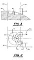
- the end mill cutter axis 54 has two degrees of motion freedom relative to the vertical plane 50 which runs through the axis of wheel 26.
- the two degrees of freedom of axis 54 are numerically controlled such that, as best shown in Figure 4, the rotating end mill cutter 52 moves perpendicular to plane 50 along the path indicated by arrow 52a, then moves in a semicircular path indicated by arrow 52b followed by movement perpendicular to plane 50 along the path indicated by arrow 52c.
- the end mill cutter leaves an island portion 31 whose significance will become apparent hereinafter.
- the wheel is rotated a calculated angular distance determined by the particular design and the machining operation is repeated.
- the inclusion of the small metal island 31 results in a guided 180° passage. This guided passage augments the work done by a given rotor for the same nozzle exit conditions and tip speed in three ways.
- the including of the bucket inner island 31 is, in effect, the creation of suction surface 31a (similar to that of an ordinary 180 bend) which transfers more power from the flowing stream to the shaft.
- steam is axially supplied to the turbine 10 via inlet casing 12.
- the flow path of the steam through the turbine 10 from inlet casing 12 to the exhaust volute casing 16 is indicated by the arrows in Figure 2. More specifically, steam serially passes around nose cone 13, through inlet guide vanes 14 and nozzles 21a defined by nozzle blades 21 to the first stage 26a of wheel or rotor 26.
- the steam passes through buckets 30a and then through vaneless diffuser 80, axial guide vanes 24 and nozzles 23a defined by nozzle blades 23 to the second stage 26b of wheel or rotor 26.
- the steam passes through buckets 30b and then passes through vaneless diffuser 81 into exhaust volute casing 16 and is exhausted from turbine 10 through side pipe discharge where the steam is either utilized in a process or condensed, etc.
- the steam In passing through the buckets of each stage of the wheel or rotor 26, the steam is turned through 180 0 by the pressure surface or wall of the buckets and thereby imparts kinetic energy to the wheel or rotor 26 causing it to rotate together with shaft 28 and any power generating ment connected thereto (not illustrated).
- This operation does not significantly differ from the basic operation of a conventional impulse turbine except that the through flow component is always radial whereas in a conventional axial machine it is always axial.
- the bucket configuration of the present invention provides a number of operating advantages over conventional designs.
- the bucket configuration of the present invention provides considerable advantages when used with low quality/wet steam or dirty gas.
- steam indicated by the arrow 60 impinges upon the pressure surface or walls 33 of the buckets 30 imparting kinetic energy to the wheel 26 and causing it to rotate in the same direction in which the steam is supplied, as indicated by arrow 27.
- the wheel tip speed for each stage is about 30 to 65% that of the steam being supplied to that stage.
- the velocity of the water droplets present in the steam is less than that of the steam as well as that of the wheel 26, in most cases, so that the wheel 26 overtakes the water droplets 62 which have a negative velocity, in most cases, relative to that of the wheel 26.
- the downstream side of the buckets would overtake and impinge against the water droplets and be eroded thereby.
- the downstream portion of the conventional bucket does not exist and cannot be eroded.
- the relative velocity of the water droplets or particles 62 is indicated by arrows 64 and represents the water contained in the steam supplied by the nozzles. The exact relative velocity and direction would depend upon the steam design conditions. Because the machining of buckets 30 is as described above, a cusp shaped portion 26' of the original surface of the rim of the rotor or wheel 26 remains after machining.
- cusp 26' represents the outer surface of the rotor or wheel 26 and is a smooth transition from the bottom 65 of the bucket 30 to the outer surface of the rotor and is in line with the nozzles
- the droplets or particles 62 when they impinge on the bottom 65 of the bucket 30 and/or cusp 26; would slide smoothly and fall into the next bucket and be entrained by the steam flow through that bucket as indicated by arrow 66.
- the particles After passing through the bucket 30 the particles are ultimately ejected and dragged with the main steam flow in a vaneless diffuser. Since the water droplets or particles 62 impinge against the cusps 26' and the bucket bottom 65 at a very low angle of incidence, there is a very little, if any, erosion. Furthermore, even if erosion occurs in severe design conditions, it would take place at essentially infinite thickness (i.e. more or less towards the center of the rotor) so that mechanical failure which arises in conventional turbines due to breakage of the blades at the root is eliminated.
- the present invention has been specifically described and illustrated in terms of a 2-stage steam turbine, other changes will occur to those skilled in the art.
- the present invention is suitable for use in a single stage turbine and this single stage can be used as the control stage of an axial flow turbine requiring such a stage.
- the structure designated 36 can be a gear box and depending upon the design, the turbine can be an independent unit, such as is illustrated, or it can be integral with the gear box.
- the rotor can be simply supported and, depending upon the RPM, the shaft can be stiff. Labyrinth seals 41 and 44 could be replaced with abraidible seals. It is therefore intended that the scope of the present invention is to be limited only by the scope of the appended claims.
Landscapes
- Engineering & Computer Science (AREA)
- Mechanical Engineering (AREA)
- General Engineering & Computer Science (AREA)
- Turbine Rotor Nozzle Sealing (AREA)
Applications Claiming Priority (2)
| Application Number | Priority Date | Filing Date | Title |
|---|---|---|---|
| US06/390,604 US4502838A (en) | 1982-06-21 | 1982-06-21 | Solid wheel turbine |
| US390604 | 1995-02-17 |
Publications (3)
| Publication Number | Publication Date |
|---|---|
| EP0097608A2 true EP0097608A2 (de) | 1984-01-04 |
| EP0097608A3 EP0097608A3 (en) | 1984-10-17 |
| EP0097608B1 EP0097608B1 (de) | 1987-08-12 |
Family
ID=23543159
Family Applications (1)
| Application Number | Title | Priority Date | Filing Date |
|---|---|---|---|
| EP83630100A Expired EP0097608B1 (de) | 1982-06-21 | 1983-06-02 | Turbinenrad mit in der Peripherie eingearbeiteten Schaufeln |
Country Status (4)
| Country | Link |
|---|---|
| US (1) | US4502838A (de) |
| EP (1) | EP0097608B1 (de) |
| JP (1) | JPS597702A (de) |
| DE (1) | DE3373004D1 (de) |
Cited By (3)
| Publication number | Priority date | Publication date | Assignee | Title |
|---|---|---|---|---|
| GB2288856A (en) * | 1994-03-25 | 1995-11-01 | Mervyn A Hutchings | Air engines |
| CN112796841A (zh) * | 2020-12-25 | 2021-05-14 | 东方电气集团东方汽轮机有限公司 | 一种减少过桥汽封漏汽量的结构 |
| EP4012158A4 (de) * | 2019-02-01 | 2023-08-30 | Byung Chul Cheon | Impulsturbine und turbinenvorrichtung |
Families Citing this family (11)
| Publication number | Priority date | Publication date | Assignee | Title |
|---|---|---|---|---|
| US4573870A (en) * | 1984-10-26 | 1986-03-04 | Elliott Turbomachinery Co., Inc. | Solid turbine wheel with guided discharge |
| JPH031865Y2 (de) * | 1985-04-04 | 1991-01-21 | ||
| JPH11343807A (ja) | 1998-06-01 | 1999-12-14 | Mitsubishi Heavy Ind Ltd | 蒸気タービンの連結静翼 |
| GB2351533B (en) * | 1999-07-01 | 2003-11-05 | Ntn Toyo Bearing Co Ltd | Air turbine spindle |
| DE102006013557B4 (de) * | 2005-03-30 | 2015-09-24 | Alstom Technology Ltd. | Rotor für eine Dampfturbine |
| JP5112975B2 (ja) * | 2008-03-10 | 2013-01-09 | 株式会社ナカニシ | スピンドル装置 |
| US20100212316A1 (en) * | 2009-02-20 | 2010-08-26 | Robert Waterstripe | Thermodynamic power generation system |
| CN102405332A (zh) | 2009-02-20 | 2012-04-04 | 热力技术有限责任公司 | 热力能量发生系统 |
| US8522552B2 (en) * | 2009-02-20 | 2013-09-03 | American Thermal Power, Llc | Thermodynamic power generation system |
| US20100257861A1 (en) * | 2009-04-09 | 2010-10-14 | Benny Lee Berry | Hybrid electric steam turbine automotive engine |
| US8001792B1 (en) * | 2010-04-08 | 2011-08-23 | Opra Technologies B.V. | Turbine inlet nozzle guide vane mounting structure for radial gas turbine engine |
Family Cites Families (19)
| Publication number | Priority date | Publication date | Assignee | Title |
|---|---|---|---|---|
| DE158212C (de) * | ||||
| FR321637A (fr) * | 1902-05-31 | 1903-01-15 | Mc Collum James Harry Keighly | Perfectionnements apportés dans les machines à turbines |
| FR358690A (fr) * | 1904-10-14 | 1906-03-03 | Rosa Rappaport | Turbine à aubes en forme de u |
| US812795A (en) * | 1904-11-16 | 1906-02-13 | Gen Electric | Bucket for turbines. |
| US835370A (en) * | 1905-09-07 | 1906-11-06 | Ball Engine Co | Bucket for steam-turbines. |
| US845059A (en) * | 1906-03-22 | 1907-02-26 | Charles W Dake | Elastic-fluid turbine. |
| US928178A (en) * | 1907-11-16 | 1909-07-13 | David Burnfield | Turbine. |
| US1038972A (en) * | 1910-02-14 | 1912-09-17 | B F Sturtevant Co | Elastic-fluid turbine. |
| US1625433A (en) * | 1925-09-12 | 1927-04-19 | Westinghouse Electric & Mfg Co | Turbine-blade shrouding |
| US1744757A (en) * | 1928-01-25 | 1930-01-28 | Auto Prime Pump Company | Method of making impellers |
| US2480807A (en) * | 1944-11-18 | 1949-08-30 | Thompson Prod Inc | Method of and apparatus for making impeller wheels |
| US2633776A (en) * | 1948-08-14 | 1953-04-07 | Kellogg M W Co | Method of manufacturing turbine blades integral with turbine rotor |
| US3147551A (en) * | 1959-10-09 | 1964-09-08 | Siemens Reiniger Werke Ag | Handpiece for dental drills or the like |
| US3471125A (en) * | 1965-04-10 | 1969-10-07 | Siemens Reiniger Werke Ag | Dental handpiece with compressed-air turbine drive |
| GB1416442A (en) * | 1972-03-15 | 1975-12-03 | Secr Defence | Turbomachinery |
| JPS4933022A (de) * | 1972-08-03 | 1974-03-26 | ||
| US4027995A (en) * | 1975-07-14 | 1977-06-07 | Berry Clyde F | Steam track turbine |
| US4150918A (en) * | 1976-01-21 | 1979-04-24 | Hollymatic Corporation | Pressure gas engine |
| US4421454A (en) * | 1979-09-27 | 1983-12-20 | Solar Turbines Incorporated | Turbines |
-
1982
- 1982-06-21 US US06/390,604 patent/US4502838A/en not_active Expired - Lifetime
-
1983
- 1983-06-02 DE DE8383630100T patent/DE3373004D1/de not_active Expired
- 1983-06-02 EP EP83630100A patent/EP0097608B1/de not_active Expired
- 1983-06-21 JP JP58111787A patent/JPS597702A/ja active Pending
Cited By (4)
| Publication number | Priority date | Publication date | Assignee | Title |
|---|---|---|---|---|
| GB2288856A (en) * | 1994-03-25 | 1995-11-01 | Mervyn A Hutchings | Air engines |
| EP4012158A4 (de) * | 2019-02-01 | 2023-08-30 | Byung Chul Cheon | Impulsturbine und turbinenvorrichtung |
| CN112796841A (zh) * | 2020-12-25 | 2021-05-14 | 东方电气集团东方汽轮机有限公司 | 一种减少过桥汽封漏汽量的结构 |
| CN112796841B (zh) * | 2020-12-25 | 2022-03-15 | 东方电气集团东方汽轮机有限公司 | 一种减少过桥汽封漏汽量的结构 |
Also Published As
| Publication number | Publication date |
|---|---|
| US4502838A (en) | 1985-03-05 |
| DE3373004D1 (en) | 1987-09-17 |
| EP0097608B1 (de) | 1987-08-12 |
| EP0097608A3 (en) | 1984-10-17 |
| JPS597702A (ja) | 1984-01-14 |
Similar Documents
| Publication | Publication Date | Title |
|---|---|---|
| US4502838A (en) | Solid wheel turbine | |
| US2918254A (en) | Turborunner | |
| US4425079A (en) | Air sealing for turbomachines | |
| US5238364A (en) | Shroud ring for an axial flow turbine | |
| US3240012A (en) | Turbo-jet powerplant | |
| US4067665A (en) | Turbine booster pump system | |
| RU2069769C1 (ru) | Впускной корпус для однопоточной осевой паровой турбины | |
| GB712051A (en) | Improvements in or relating to axial-flow fluid machines | |
| JPH079194B2 (ja) | ガスタービン・エンジンの冷却空気転送手段 | |
| CN110206592B (zh) | 用于径流式叶轮机械的耐高温高压一体式叶轮-密封结构 | |
| JPH0250320B2 (de) | ||
| US4306834A (en) | Balance piston and seal for gas turbine engine | |
| US1926225A (en) | Turbo compressor | |
| US4421454A (en) | Turbines | |
| US4435121A (en) | Turbines | |
| US2637984A (en) | Turbine | |
| CN102661174A (zh) | 增压透平膨胀机 | |
| US5167486A (en) | Turbo-machine stage having reduced secondary losses | |
| US3120374A (en) | Exhaust scroll for turbomachine | |
| US2640678A (en) | Fluid translating device | |
| CN114251130B (zh) | 一种用于控制叶顶泄漏流的鲁棒性转子结构和动力系统 | |
| US6272844B1 (en) | Gas turbine engine having a bladed disk | |
| US2962206A (en) | Centrifugal compressor for a gas turbine engine | |
| EP0097605B1 (de) | Impulsturbine für Überschallströmung | |
| US20240368993A1 (en) | Device for sealing and reinjecting a bypass flow for a turbine nozzle |
Legal Events
| Date | Code | Title | Description |
|---|---|---|---|
| PUAI | Public reference made under article 153(3) epc to a published international application that has entered the european phase |
Free format text: ORIGINAL CODE: 0009012 |
|
| AK | Designated contracting states |
Designated state(s): CH DE FR GB IT LI SE |
|
| PUAL | Search report despatched |
Free format text: ORIGINAL CODE: 0009013 |
|
| AK | Designated contracting states |
Designated state(s): CH DE FR GB IT LI SE |
|
| 17P | Request for examination filed |
Effective date: 19841212 |
|
| GRAA | (expected) grant |
Free format text: ORIGINAL CODE: 0009210 |
|
| AK | Designated contracting states |
Kind code of ref document: B1 Designated state(s): CH DE FR GB IT LI SE |
|
| ET | Fr: translation filed | ||
| REF | Corresponds to: |
Ref document number: 3373004 Country of ref document: DE Date of ref document: 19870917 |
|
| ITF | It: translation for a ep patent filed | ||
| PLBE | No opposition filed within time limit |
Free format text: ORIGINAL CODE: 0009261 |
|
| STAA | Information on the status of an ep patent application or granted ep patent |
Free format text: STATUS: NO OPPOSITION FILED WITHIN TIME LIMIT |
|
| 26N | No opposition filed | ||
| PGFP | Annual fee paid to national office [announced via postgrant information from national office to epo] |
Ref country code: FR Payment date: 19890508 Year of fee payment: 7 |
|
| PGFP | Annual fee paid to national office [announced via postgrant information from national office to epo] |
Ref country code: SE Payment date: 19890512 Year of fee payment: 7 |
|
| PGFP | Annual fee paid to national office [announced via postgrant information from national office to epo] |
Ref country code: CH Payment date: 19890522 Year of fee payment: 7 |
|
| PGFP | Annual fee paid to national office [announced via postgrant information from national office to epo] |
Ref country code: GB Payment date: 19890531 Year of fee payment: 7 |
|
| ITTA | It: last paid annual fee | ||
| PG25 | Lapsed in a contracting state [announced via postgrant information from national office to epo] |
Ref country code: GB Effective date: 19900602 |
|
| PG25 | Lapsed in a contracting state [announced via postgrant information from national office to epo] |
Ref country code: SE Effective date: 19900603 |
|
| PG25 | Lapsed in a contracting state [announced via postgrant information from national office to epo] |
Ref country code: LI Effective date: 19900630 Ref country code: CH Effective date: 19900630 |
|
| GBPC | Gb: european patent ceased through non-payment of renewal fee | ||
| PG25 | Lapsed in a contracting state [announced via postgrant information from national office to epo] |
Ref country code: FR Effective date: 19910228 |
|
| REG | Reference to a national code |
Ref country code: CH Ref legal event code: PL |
|
| REG | Reference to a national code |
Ref country code: FR Ref legal event code: ST |
|
| EUG | Se: european patent has lapsed |
Ref document number: 83630100.2 Effective date: 19910206 |
|
| PGFP | Annual fee paid to national office [announced via postgrant information from national office to epo] |
Ref country code: DE Payment date: 19980629 Year of fee payment: 16 |
|
| PG25 | Lapsed in a contracting state [announced via postgrant information from national office to epo] |
Ref country code: DE Free format text: LAPSE BECAUSE OF NON-PAYMENT OF DUE FEES Effective date: 20000503 |