EP0097610A1 - Verfahren und Einrichtung zum Entleeren von metallurgischen Gefässen - Google Patents
Verfahren und Einrichtung zum Entleeren von metallurgischen Gefässen Download PDFInfo
- Publication number
- EP0097610A1 EP0097610A1 EP83630104A EP83630104A EP0097610A1 EP 0097610 A1 EP0097610 A1 EP 0097610A1 EP 83630104 A EP83630104 A EP 83630104A EP 83630104 A EP83630104 A EP 83630104A EP 0097610 A1 EP0097610 A1 EP 0097610A1
- Authority
- EP
- European Patent Office
- Prior art keywords
- plug
- container
- taphole
- tap hole
- slag
- Prior art date
- Legal status (The legal status is an assumption and is not a legal conclusion. Google has not performed a legal analysis and makes no representation as to the accuracy of the status listed.)
- Granted
Links
Images
Classifications
-
- C—CHEMISTRY; METALLURGY
- C21—METALLURGY OF IRON
- C21C—PROCESSING OF PIG-IRON, e.g. REFINING, MANUFACTURE OF WROUGHT-IRON OR STEEL; TREATMENT IN MOLTEN STATE OF FERROUS ALLOYS
- C21C5/00—Manufacture of carbon-steel, e.g. plain mild steel, medium carbon steel or cast steel or stainless steel
- C21C5/28—Manufacture of steel in the converter
- C21C5/42—Constructional features of converters
- C21C5/46—Details or accessories
- C21C5/4653—Tapholes; Opening or plugging thereof
-
- C—CHEMISTRY; METALLURGY
- C21—METALLURGY OF IRON
- C21C—PROCESSING OF PIG-IRON, e.g. REFINING, MANUFACTURE OF WROUGHT-IRON OR STEEL; TREATMENT IN MOLTEN STATE OF FERROUS ALLOYS
- C21C5/00—Manufacture of carbon-steel, e.g. plain mild steel, medium carbon steel or cast steel or stainless steel
- C21C5/28—Manufacture of steel in the converter
- C21C5/42—Constructional features of converters
-
- B—PERFORMING OPERATIONS; TRANSPORTING
- B22—CASTING; POWDER METALLURGY
- B22D—CASTING OF METALS; CASTING OF OTHER SUBSTANCES BY THE SAME PROCESSES OR DEVICES
- B22D1/00—Treatment of fused masses in the ladle or the supply runners before casting
- B22D1/002—Treatment with gases
- B22D1/005—Injection assemblies therefor
Definitions
- the present invention relates to a method and a device for emptying tilting metallurgical vessels, in particular steelworks converters, comprising a tap hole arranged in the side wall and containing molten metal on which slag is swimming.
- DE-OS 26 39 712 discloses a taphole closing device comprising a closing body which can be inserted into the poured hole which leaves an annular slot free relative to the wall of the taphole and which contains a pressurized gas line.
- the closure body has an outer wall which tapers towards the orifice of the pressurized gas line. The slag is forced back into the container under the effect of the gas flow.
- This device which is subject to significant wear in large converters, has been improved (see EP 10.082) in that the external lateral surface of the shutter consists of a surface in the form of a spherical cap which , on the side of the mouth, turns into a frusto-conical surface.
- the shutter is made of gray cast iron. Both devices have the disadvantage that they require large quantities of gas to seal the taphole. In addition, there are problems of blockage of the mouth of the gas pipe of the shutter.
- the object of the present invention is to provide a remedy for the drawbacks described, and to eliminate in a large proportion the entrainment of slag when emptying metallurgical vessels.
- the method according to the invention which is characterized in that it ensures, at the latest after the end of metallurgical operations, the sealed closure of the taphole using a plug capable of being attacked by the molten mass, in that the container is tilted, in that a bubbling gas is introduced around the taphole in the container through permeable elements, in that the closing hole is closed pouring using a new stopper as soon as the first slag elements are found and the container is tilted to the starting position.
- a bubbling gas is introduced around the taphole in the container through permeable elements
- the closing hole is closed pouring using a new stopper as soon as the first slag elements are found and the container is tilted to the starting position.
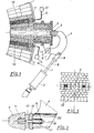
- Fig. 1 part of a refining crucible 1 whose tap hole 2 is closed by a plug 3.
- the plug 3 is mounted on an arm 4, which pivots about an axis 5 fixed on the wall of the tap hole .
- the arm 4 is provided with a stop 6. (The counter-stop mounted on the wall of the converter is not shown).
- a hydraulic cylinder 7, operable in both directions, acts by means of a rod 8 and a fork 9 on the arm 4.
- the cylinder 7 can pivot around an axis integral with the wall of the converter.
- the plug 3 has the shape of a truncated cone, slightly chamfered.
- the large base of the truncated cone has a cylindrical recess 14 in which is received a lug mounted on the arm 4 (see also Fig. 2).
- the plug which is held on the lug by friction is preferably made of an inexpensive, easily machinable and relatively soft material such as wood, preferably fir.
- the surface of the plug is advantageously covered with a de- refractory material layer.
- Two elements 10 permeable to a bubbling agent are located on either side of the tap hole 2 (see FIG. 3). The optimal place where these elements are placed is preferably determined experimentally for each converter. By positioning them about 0.5 m from the axis of the tap hole, we obtained the expected result for our 150-ton converter.
- Permeable elements suitable for implementing the invention have been described in patents LU 82.552, LU 82.553, LU 82.554. They consist of several neighboring elongated segments, of rectangular section, surrounded by a metal box. On the cold side of the permeable element 10, a distribution chamber 11 is welded to the walls of the box. Conduits 12 connect this chamber 11 to a source 13 of bubbling agent. The bubbling fluid is passed at the interface of the different segments. It follows that the permeable elements 10 create a well distributed flow of fluid.
- a tube 20 is fixed, onto which a base 16 is welded, on the arm 4.
- a bolt 18 screwed into a ball joint 15 provided with the stopper lug ensures, by through the spring 17 and the washer 19, the bearing of the ball joint 15 on the base 16.
- the jack 7 can be kept in the extended position, as shown in FIG. 1, to ensure that the plug 3 is held in the mouth of the taphole 2.
- the taphole is preferably always closed, except during the pouring operation. This limits heat loss and avoids the escape of flame and slag during blowing.
- the jack 7 withdraws the arm 4 until it stops.
- the plug 3 remains stuck in the tap hole 2.
- the liquid mass comes into contact with the plug during the tilting and destroys it in a few seconds. At this time the converter is in such a position that only metal is in the immediate vicinity of the tap hole.
- a new plug 3 is positioned on the lug of the arm 4.
- the jack 7 is pressurized and the plug 5 is pressed into the tap hole.
- the plug has a reduced mass, the closure is therefore quick.
- the position of the shutter is preferably adjustable on the axis of the tap hole. It is also noted that since the plug remains stuck respectively held in the taphole between two emptying operations, the use of a second plug is superfluous.
- the bubbling agent is usefully a neutral gas such as argon, nitrogen or possibly carbon dioxide.
- a gas flow of 2-3 Nm 3 / h eure ensures the permeability of the refractory elements.
- the gas flow rate is increased to reach 5-10 Nm 3 / hour. Note here that higher flow rates cause projections, which mix with the slag and which are then entrained with them towards the tap hole.
- an improvement in the ferro-manganese yield ranging from 3 to 7% has been observed for semi-quenched steels, which is equivalent on average to a saving of 0.35 kg / t steel .
- the number of flows with high rephosphorization, on the order of 0.025 XP decreased by more than half, while those with low rephosphorization, on the order of 0.002% P, easily doubled.
- the invention has been described and shows the most convincing advantages in relation to a tilting crucible, it can also be used with static metallurgical vessels having a tap hole provided in the bottom.
- the number of permeable elements need not necessarily be taken to be two, and the bubbling gases suitable for implementing the invention are not only argon, nitrogen or carbon dioxide.
Landscapes
- Engineering & Computer Science (AREA)
- Chemical & Material Sciences (AREA)
- Manufacturing & Machinery (AREA)
- Materials Engineering (AREA)
- Metallurgy (AREA)
- Organic Chemistry (AREA)
- Mechanical Engineering (AREA)
- Carbon Steel Or Casting Steel Manufacturing (AREA)
- Furnace Charging Or Discharging (AREA)
- Treatment Of Steel In Its Molten State (AREA)
- Manufacture And Refinement Of Metals (AREA)
- Waste-Gas Treatment And Other Accessory Devices For Furnaces (AREA)
- Vertical, Hearth, Or Arc Furnaces (AREA)
Priority Applications (1)
| Application Number | Priority Date | Filing Date | Title |
|---|---|---|---|
| AT83630104T ATE20440T1 (de) | 1982-06-18 | 1983-06-15 | Verfahren und einrichtung zum entleeren von metallurgischen gefaessen. |
Applications Claiming Priority (4)
| Application Number | Priority Date | Filing Date | Title |
|---|---|---|---|
| LU84213A LU84213A1 (fr) | 1982-06-18 | 1982-06-18 | Dispositif pour vidanger des recipients metallurgiques |
| LU84213 | 1982-06-18 | ||
| LU84237 | 1982-06-29 | ||
| LU84237A LU84237A1 (de) | 1982-06-29 | 1982-06-29 | Vorrichtung zum verschliessen des abstichloches eines metallurgischen gefaesses |
Publications (2)
| Publication Number | Publication Date |
|---|---|
| EP0097610A1 true EP0097610A1 (de) | 1984-01-04 |
| EP0097610B1 EP0097610B1 (de) | 1986-06-18 |
Family
ID=26640291
Family Applications (1)
| Application Number | Title | Priority Date | Filing Date |
|---|---|---|---|
| EP83630104A Expired EP0097610B1 (de) | 1982-06-18 | 1983-06-15 | Verfahren und Einrichtung zum Entleeren von metallurgischen Gefässen |
Country Status (15)
| Country | Link |
|---|---|
| EP (1) | EP0097610B1 (de) |
| KR (1) | KR840005172A (de) |
| AR (1) | AR230796A1 (de) |
| AU (1) | AU1591983A (de) |
| BR (1) | BR8303246A (de) |
| CA (1) | CA1206752A (de) |
| DD (1) | DD209851C4 (de) |
| DE (1) | DE3364174D1 (de) |
| DK (1) | DK280383A (de) |
| ES (1) | ES8405444A1 (de) |
| FI (1) | FI831964L (de) |
| HU (1) | HU187104B (de) |
| IN (1) | IN157657B (de) |
| NO (1) | NO832200L (de) |
| PT (1) | PT76879B (de) |
Cited By (1)
| Publication number | Priority date | Publication date | Assignee | Title |
|---|---|---|---|---|
| WO2002081759A1 (de) * | 2001-04-05 | 2002-10-17 | Georgsmarienhütte Gmbh | Verfahren und vorrichtung zur verhinderung des mitfliessens von schlacke beim abstich einer metallschmelze |
Families Citing this family (1)
| Publication number | Priority date | Publication date | Assignee | Title |
|---|---|---|---|---|
| DE4211598C1 (de) * | 1992-04-07 | 1993-01-14 | Oesterreichische Magnesit Ag, Radenthein, Kaernten, At |
Citations (4)
| Publication number | Priority date | Publication date | Assignee | Title |
|---|---|---|---|---|
| DE2514218B2 (de) * | 1974-04-08 | 1976-09-02 | Salvagnini, Mirella, Padua (Italien) | Auslassvorrichtung mit beweglichem stopfen zur kontrolle des flusses geschmolzener metalle aus entsprechenden behaeltern |
| DE2724227A1 (de) * | 1976-07-06 | 1978-01-19 | Daussan | Vorrichtung zum verschluss der giessoeffnung eines behaelters zum umfuellen von geschmolzenem metall |
| EP0043338A1 (de) * | 1980-06-25 | 1982-01-06 | Arbed S.A. | Feuerfeste, gasdurchlässige Baukörper |
| EP0043787A1 (de) * | 1980-07-09 | 1982-01-13 | Arbed S.A. | Feuerfeste, gasdurchlässige Baukörper |
-
1983
- 1983-05-20 CA CA000428620A patent/CA1206752A/fr not_active Expired
- 1983-06-01 FI FI831964A patent/FI831964L/fi not_active Application Discontinuation
- 1983-06-14 DD DD83252013A patent/DD209851C4/de not_active IP Right Cessation
- 1983-06-15 EP EP83630104A patent/EP0097610B1/de not_active Expired
- 1983-06-15 DE DE8383630104T patent/DE3364174D1/de not_active Expired
- 1983-06-16 AR AR293346A patent/AR230796A1/es active
- 1983-06-16 PT PT76879A patent/PT76879B/pt unknown
- 1983-06-17 HU HU832177A patent/HU187104B/hu not_active IP Right Cessation
- 1983-06-17 ES ES523380A patent/ES8405444A1/es not_active Expired
- 1983-06-17 DK DK280383A patent/DK280383A/da not_active Application Discontinuation
- 1983-06-17 BR BR8303246A patent/BR8303246A/pt not_active IP Right Cessation
- 1983-06-17 NO NO832200A patent/NO832200L/no unknown
- 1983-06-17 AU AU15919/83A patent/AU1591983A/en not_active Abandoned
- 1983-06-18 KR KR1019830002739A patent/KR840005172A/ko not_active Withdrawn
- 1983-06-23 IN IN785/CAL/83A patent/IN157657B/en unknown
Patent Citations (4)
| Publication number | Priority date | Publication date | Assignee | Title |
|---|---|---|---|---|
| DE2514218B2 (de) * | 1974-04-08 | 1976-09-02 | Salvagnini, Mirella, Padua (Italien) | Auslassvorrichtung mit beweglichem stopfen zur kontrolle des flusses geschmolzener metalle aus entsprechenden behaeltern |
| DE2724227A1 (de) * | 1976-07-06 | 1978-01-19 | Daussan | Vorrichtung zum verschluss der giessoeffnung eines behaelters zum umfuellen von geschmolzenem metall |
| EP0043338A1 (de) * | 1980-06-25 | 1982-01-06 | Arbed S.A. | Feuerfeste, gasdurchlässige Baukörper |
| EP0043787A1 (de) * | 1980-07-09 | 1982-01-13 | Arbed S.A. | Feuerfeste, gasdurchlässige Baukörper |
Cited By (3)
| Publication number | Priority date | Publication date | Assignee | Title |
|---|---|---|---|---|
| WO2002081759A1 (de) * | 2001-04-05 | 2002-10-17 | Georgsmarienhütte Gmbh | Verfahren und vorrichtung zur verhinderung des mitfliessens von schlacke beim abstich einer metallschmelze |
| US6951296B2 (en) | 2001-04-05 | 2005-10-04 | Georgsmarienhütte Gmbh | Method and device for preventing slag from flowing along when tapping a molten metal |
| CZ301430B6 (cs) * | 2001-04-05 | 2010-02-24 | Georgsmarienhütte Gmbh | Zarízení k zamezení spolecného proudení strusky pri odpichu kovové taveniny |
Also Published As
| Publication number | Publication date |
|---|---|
| KR840005172A (ko) | 1984-11-05 |
| NO832200L (no) | 1983-12-19 |
| IN157657B (de) | 1986-05-10 |
| EP0097610B1 (de) | 1986-06-18 |
| FI831964A7 (fi) | 1983-12-19 |
| PT76879B (fr) | 1986-01-27 |
| DD209851A5 (de) | 1984-05-23 |
| ES523380A0 (es) | 1984-06-01 |
| BR8303246A (pt) | 1983-12-13 |
| FI831964A0 (fi) | 1983-06-01 |
| PT76879A (fr) | 1983-07-01 |
| AR230796A1 (es) | 1984-07-31 |
| AU1591983A (en) | 1983-12-22 |
| FI831964L (fi) | 1983-12-19 |
| CA1206752A (fr) | 1986-07-02 |
| DK280383A (da) | 1983-12-19 |
| ES8405444A1 (es) | 1984-06-01 |
| DE3364174D1 (en) | 1986-07-24 |
| DD209851C4 (de) | 1985-12-18 |
| HU187104B (en) | 1985-11-28 |
| DK280383D0 (da) | 1983-06-17 |
Similar Documents
| Publication | Publication Date | Title |
|---|---|---|
| EP0048641B2 (de) | Vorrichtung zum Schützen geschmolzenen Metalls in Schieberverschlüssen | |
| FR2499229A1 (fr) | Dispositif pour boucher le trou de coulee d'un recipient metallurgique | |
| FR2535835A1 (fr) | Four a arc basculant | |
| EP0094926A1 (de) | Mündung zum Einführen eines Schutzgases in ein Giessrohr | |
| LU83926A1 (fr) | Procede et appareil de coulee en source d'un metal fondu | |
| NZ241288A (en) | Slag carryover prevented by floating refractory plug with mating | |
| EP0097610B1 (de) | Verfahren und Einrichtung zum Entleeren von metallurgischen Gefässen | |
| MXPA00012305A (es) | Procedimiento y dispositivo para la hermetizacion dle una abertura de sangria en recipientes metalurgicos. | |
| FR2611151A1 (fr) | Dispositif de prechauffage et/ou d'obturation et de debouchage d'un orifice de coulee et procede pour sa mise en oeuvre | |
| CA2235202A1 (fr) | Repartiteur de coulee continue des metaux, du type comportant au moins une torche a plasma pour le rechauffage du metal | |
| EP1457575B1 (de) | Vorrichtung zum Beobachten von Chargiergut in einem Elektrostahlofen | |
| LU84213A1 (fr) | Dispositif pour vidanger des recipients metallurgiques | |
| FR2513909A1 (fr) | Procede et appareil pour le traitement d'un metal liquide dans un recipient | |
| FR2629101A1 (fr) | Brique pour l'introduction de gaz ou de produits de reaction dans un recipient de coulee metallurgique | |
| EP0589762B1 (de) | Giessrohr für Metall und Verfahren zu seiner Herstellung | |
| EP0203979B1 (de) | Verbesserungen an giesspfannen für flüssige metalle | |
| FR2716819A1 (fr) | Procédé et dispositif de coulée. | |
| FR2728491A1 (fr) | Dispositif de coulee d'un metal liquide avec injection d'un gaz inerte dans le metal liquide en cours de coulee | |
| EP0242347A2 (de) | Vorrichtung zum Giessen einer flüssig-festen Mischung | |
| EP0302040B1 (de) | Verbesserungen an Pfannen zum Giessen von Metall | |
| FR2627715A1 (fr) | Busette de coulee pour ouverture assistee, dispositif l'incorporant et procede de mise en oeuvre | |
| EP0282824A2 (de) | Vorrichtung zum Entleeren von metallurgischen Gefässen | |
| EP0028569A1 (de) | Verfahren zum Spülen einer Metallschmelze durch Einblasen von Gas | |
| FR2658277A1 (fr) | Recipient metallurgique equipe d'au moins une electrode traversant sa paroi. | |
| FR2467651A1 (fr) | Dispositif pour deboucher l'orifice de coulee d'un recipient metallurgique |
Legal Events
| Date | Code | Title | Description |
|---|---|---|---|
| PUAI | Public reference made under article 153(3) epc to a published international application that has entered the european phase |
Free format text: ORIGINAL CODE: 0009012 |
|
| AK | Designated contracting states |
Designated state(s): AT BE DE FR GB IT NL SE |
|
| 17P | Request for examination filed |
Effective date: 19840620 |
|
| GRAA | (expected) grant |
Free format text: ORIGINAL CODE: 0009210 |
|
| AK | Designated contracting states |
Kind code of ref document: B1 Designated state(s): AT BE DE FR GB IT NL SE |
|
| REF | Corresponds to: |
Ref document number: 20440 Country of ref document: AT Date of ref document: 19860715 Kind code of ref document: T |
|
| ITF | It: translation for a ep patent filed | ||
| REF | Corresponds to: |
Ref document number: 3364174 Country of ref document: DE Date of ref document: 19860724 |
|
| PLBE | No opposition filed within time limit |
Free format text: ORIGINAL CODE: 0009261 |
|
| STAA | Information on the status of an ep patent application or granted ep patent |
Free format text: STATUS: NO OPPOSITION FILED WITHIN TIME LIMIT |
|
| 26N | No opposition filed | ||
| PGFP | Annual fee paid to national office [announced via postgrant information from national office to epo] |
Ref country code: NL Payment date: 19870630 Year of fee payment: 5 |
|
| PG25 | Lapsed in a contracting state [announced via postgrant information from national office to epo] |
Ref country code: GB Effective date: 19880615 |
|
| PG25 | Lapsed in a contracting state [announced via postgrant information from national office to epo] |
Ref country code: SE Effective date: 19880616 |
|
| BERE | Be: lapsed |
Owner name: ARBED S.A. Effective date: 19880630 |
|
| PG25 | Lapsed in a contracting state [announced via postgrant information from national office to epo] |
Ref country code: NL Effective date: 19890101 |
|
| NLV4 | Nl: lapsed or anulled due to non-payment of the annual fee | ||
| GBPC | Gb: european patent ceased through non-payment of renewal fee | ||
| PG25 | Lapsed in a contracting state [announced via postgrant information from national office to epo] |
Ref country code: FR Free format text: LAPSE BECAUSE OF NON-PAYMENT OF DUE FEES Effective date: 19890228 |
|
| REG | Reference to a national code |
Ref country code: FR Ref legal event code: ST |
|
| PG25 | Lapsed in a contracting state [announced via postgrant information from national office to epo] |
Ref country code: BE Effective date: 19890630 |
|
| ITTA | It: last paid annual fee | ||
| PGFP | Annual fee paid to national office [announced via postgrant information from national office to epo] |
Ref country code: DE Payment date: 19930521 Year of fee payment: 11 |
|
| PGFP | Annual fee paid to national office [announced via postgrant information from national office to epo] |
Ref country code: AT Payment date: 19930614 Year of fee payment: 11 |
|
| PG25 | Lapsed in a contracting state [announced via postgrant information from national office to epo] |
Ref country code: AT Effective date: 19940615 |
|
| EUG | Se: european patent has lapsed |
Ref document number: 83630104.4 Effective date: 19890220 |
|
| PG25 | Lapsed in a contracting state [announced via postgrant information from national office to epo] |
Ref country code: DE Effective date: 19950301 |