EP0097723B1 - Automatic equalizer and method of initialization thereof - Google Patents
Automatic equalizer and method of initialization thereof Download PDFInfo
- Publication number
- EP0097723B1 EP0097723B1 EP83900068A EP83900068A EP0097723B1 EP 0097723 B1 EP0097723 B1 EP 0097723B1 EP 83900068 A EP83900068 A EP 83900068A EP 83900068 A EP83900068 A EP 83900068A EP 0097723 B1 EP0097723 B1 EP 0097723B1
- Authority
- EP
- European Patent Office
- Prior art keywords
- series
- signal
- data
- single pulse
- data series
- Prior art date
- Legal status (The legal status is an assumption and is not a legal conclusion. Google has not performed a legal analysis and makes no representation as to the accuracy of the status listed.)
- Expired
Links
Images


Classifications
-
- H—ELECTRICITY
- H04—ELECTRIC COMMUNICATION TECHNIQUE
- H04L—TRANSMISSION OF DIGITAL INFORMATION, e.g. TELEGRAPHIC COMMUNICATION
- H04L25/00—Baseband systems
- H04L25/02—Details ; arrangements for supplying electrical power along data transmission lines
- H04L25/03—Shaping networks in transmitter or receiver, e.g. adaptive shaping networks
- H04L25/03006—Arrangements for removing intersymbol interference
- H04L25/03012—Arrangements for removing intersymbol interference operating in the time domain
- H04L25/03114—Arrangements for removing intersymbol interference operating in the time domain non-adaptive, i.e. not adjustable, manually adjustable, or adjustable only during the reception of special signals
- H04L25/03133—Arrangements for removing intersymbol interference operating in the time domain non-adaptive, i.e. not adjustable, manually adjustable, or adjustable only during the reception of special signals with a non-recursive structure
Definitions
- the present invention relates to an automatic equalization device provided in a modem in a receiver in a digital data transmission system and to a method of starting-up the automatic equalization device, particularly a method for starting-up an automatic equalization device at a high speed.
- a master station communicates selectively with one of a plurality of the slave stations.
- a transmitter and a receiver of the master station are connected through a telephone transmission line with receivers and transmitters of the slave stations.
- the transmitter of the master station is always connected in an on-line manner with the receivers of the slave stations.
- the master station polls each of the slave stations in sequence. Such a polled slave station transmits an "acknowledgement" signal in response to a received "request for transmission" signal and subsequently transmits the data if the slave station has data to be transmitted.
- a modem It is necessary for a modem to adjust its receiver characteristics to the characteristics of the telephone transmission line prior to the actual receipt of data from one of the slave stations.
- the characteristics of the telephone transmission line vary for each slave station, primarily because of the change of distance between the master station and slave stations.
- Once the receiver is adjusted to the telephone transmission line it is possible to satisfactorily track the change of line characteristics using known, relatively slow speed methods.
- the receiver first receives the training data there is a great difference in the characteristics of the receiver and the characteristic of the line. Under such start-up conditions, it takes about 2 seconds to adjust the receiver to the line by the known, relatively slow speed tracking method.
- the total adjustment time of one request for transmission equals the unit adjustment time multiplied by the number of the slave stations. This total adjustment time is a key factor which significantly reduces the efficiency of data transmission in prior art systems.
- the signal series i.e., the training signal for the start-up of the equalization device
- CCITT recommendations prescribe the transmission of a binary pseudo random data code (hereinafter referred to as a PN code).
- PN code binary pseudo random data code
- various methods have been proposed in which, to initialize the correction coefficient (tap coefficient) of the equalization device from the PN code, the correlation between the data and the error signal is calculated and used to correct and determine the tap coefficient.
- such methods have disadvantages of requiring a large, complicated circuit for calculating the correlation and requiring a considerably long time for determining the tap coefficient of the equalization device. For example, about 250 msec are required from a request for transmission to the transmission of the data.
- U.S. Patent No. 3,962,637 to David M. Motley et al. proposed a method for the high-speed start-up of an equalization device in a receiver.
- a special signal comprising the three segments mentioned below is used for the training signal for the start-up of the equalization device.
- a tone signal obtained by modulating a carrier signal in a predetermined phase and amplitude is transmitted.
- a signal obtained by modulating the carrier signal by the data series by which data series the transmission timing, i.e., band rate clock period, can be discriminated is transmitted.
- a signal obtained by modulating the carrier signal by single pulse (impulse) data is transmitted.
- the single pulse signal extracted in the third segment has been deformed by the transfer function (impulse response characteristic) of the transmission line.
- the equalization device in the receiver compensates the distortion (deformation) of the signal on the line. Fundamentally, it is ideal that the equalization device have inverse characteristics of the transfer function of the line. Accordingly, in the above-referenced U.S. patent, the tap coefficient is calculated and determined on the basis of the impulse response characteristics of the transmission line extracted in the third segment of the training signal such that the equalization device has inverse characteristics of the line.
- the technique disclosed in the above-referenced U.S. patent greatly reduces the time required for initializing the tap coefficient of the equalization device in the receiver compared with the case where the above-described PN code is used. For example, the time required from a request for transmission to transmission of data can be reduced to less than 30 msec.
- a method of starting up an automatic equalisation device in accordance with the first aspect of this invention comprises the steps of:-
- the impulse signal extracted in the third segment of the training signal is, in general, asymmetrical with respect to time.
- the signal transmitted on the line in the above-described third segment only contains the carrier signal when the single pulse signal exists.
- the phase of carrier signal for demodulation in the first and the second segment is adjusted, the phase is not adjusted in the third segment.
- the phase can be guaranteed.
- a timing signal for sampling can be extracted whereas in the US patent there is a possibility of asynchronism.
- FIG. 1 A receiver equipped with an automatic equalization device according to the present invention is illustrated in Fig. 1.
- a transmitter 1 receives a transmission request signal (RS), it generates training data in a training data generating unit (TRG) 11 and supplies the training data to the modulation unit (MOD) 12.
- MOD 12 carries out quadrature-amplitude modulation on the carrier signal and a carrier signal generating unit (CRG) 13 based on the training data and transmits the modulated signal to the receiver 2 through the transmission line L.
- the setting of the starting-up condition for receiving the data signal is carried out on basis of the received training signal. Predicting the time when the setting of the starting-up condition will be finished, the transmitter 1 generates a transmission ready signal CS and starts to transmit the signal modulated by the transmitting data SD to the receiver 2.
- the modulation unit 12 of the transmitter 1 carries out quadrature amplitude modulation into 16 values on the carrier signal from the carrier generating unit 13 as shown, for example, in Fig. 2.
- each signal point shown in Fig. 2 corresponds to the amplitude and phase of the modulated signal and can be expressed in a complex number notation.
- the receiver 2 of Fig. 1 comprises a demodulation unit (DEM) 21 for receiving and demodulating the signal transmitted from transmitter 1, a single pulse extraction unit 22 for extracting a signal corresponding to a single pulse signal from the training data demodulated in the demodulation unit 21, and a first and a second equalizer unit (EQL 1 and EQL 2) started up on the basis of the extracted data corresponding to the single pulse signal.
- DEM demodulation unit
- EQL 1 and EQL 2 a first and a second equalizer unit
- TM is a timing signal for data transmission
- TRD is training data
- TRS is a carrier signal modulated by TRD.
- the training data TRD has three segments SEG1, SEG2, and SEG3.
- the training signal TRS is a signal modulated with constant data and hence has a constant amplitude and a constant phase.
- the demodulation portion (DEM) 21 of the receiver 2 the adjustment of the automatic gain control AGC can be carried out while this first segment SEG1 is received.
- the training signal TRS is modulated alternatively with two data "A" and "-A” which have the opposite phase and the same amplitude. For example, such two data "A” and "-A” are shown as D A and D_ A in Fig. 2.
- the timing signal for data transmission is extracted from the signal in the second segment SEG2.
- the training data in the third segment SEG3 is alternately expressed as data "A" and "-A” except at time t 3 where the data "A" appears successively.
- SA1 shows only a portion of the training data in the third segment SEG3
- SA2 shows that obtained by delaying it by one data symbol.
- FIG. 4 A flow chart of the start-up of the automatic equalization device of the receiver 2 in Fig. 2 using the training signal of Fig. 3 is illustrated in Fig. 4.
- the received data series (expressed in complex numbers) corresponding to the third segment SEG3 of the training signal demodulated in the demodulation unit 2 is supplied to the single pulse extraction circuit REP.
- REP the received data series is added to one obtained by delaying that data series by one data symbol.
- This data series P j may be deemed an ideal single pulse shown in Fig. 3 distorted by the transmission line L.
- the data series P j corresponding to the single pulse extracted as described above is supplied to the normalization circuit NR, and is normalized in NR.
- the normalized data series X j is supplied to the complex conjugate derivation circuit CN.
- the derived complex conjugate data series C j is initialized in the first tap coefficient register TPR1 as the tap coefficient of the first equalization circuit (EQL1) 23.
- the normalized data series x j and its complex conjugate data series C J are supplied to the computing circuit CNT1 of the first equalization circuit 23, and the auto-correlation series Am is calculated.
- the calculation of the auto-correlation series Am is carried out as follows. First, regarding the 0-th order correlation A o ,
- the auto-correlation series A m is supplied to the computing circuit CNT2 of the second equalization circuit (EQL2) 24, and the first-order approximate series B J (1 ) of the inverse characteristic matrix is obtained as follows.
- the data series B J (1) obtained in the fifth step 5 is used as the tap coefficient B j of the second equalization circuit to calculate the equalized output S with the auto-correlation series A m as the tap data. Then, the output S is compared with the reference output series Ref, and the tap coefficient B j is corrected successively so as to make the error approach zero.
- the equalized output S is the data series S L given as follows:
- the initialization of the tap coefficient of the automatic equalization device is completed. Predicting the time when the start-up in the receiver 2 is completed as described above, the transmitter 1 starts to transmit the transmission data.
- the received data signal is demodulated in the data series in the demodulation unit 21 and supplied to the first equalization circuit 23.
- the first equalized output is calculated from the received data series by the first equalized output circuit OPU1 using the tap coefficient C J in the first tap coefficient register TPR1.
- the equalized output data series from the first equalization circuit 23 is supplied to the equalized output circuit OPU2 of the second equalization circuit 24, and the final equalized output data is calculated using the second tap coefficient B j .
- it is possible to form a single equalized output circuit for the received data by calculating a combined tap coefficient from the first tap coefficient C J and the second tap coefficient B J by a convolution operation.
- FIG. 5 An automatic equalization device in accordance with one embodiment of the present invention is illustrated in detail in Fig. 5.
- the received signal after demodulation by the demodulation unit 21, is equalized by the first equalization circuit 23 and the second equalization circuit 24.
- the equalized output is data discriminated in the data discrimination unit 25 and then output as output data.
- the output signal of the demodulation unit 21 is supplied to the single pulse extraction unit 22, and the first and second equalization circuits 23 and 24 are started up in accordance with the extracted single pulse.
- the demodulation unit 21 has a filter circuit (FIL) 211 for removing the noise from the received signal, an automatic gain control circuit (AGC) 212 for adjusting the level of the received signal, a demodulation circuit (DEM) 213 for demodulation of the quadrature-amplitude modulation, and a roll-off filter circuit (ROF) 214 for removing the high frequency component from the demodulated signal.
- FIL filter circuit
- AGC automatic gain control circuit
- DEM demodulation circuit
- ROF roll-off filter circuit
- the single pulse extraction unit 22 has an extraction circuit (REP) 221 for extracting the data series corresponding to the single pulse signal from the training signal, a normalization circuit (NR) 222 for normalizing the extracted data series, and a complex conjugate derivation circuit (CN) 223 for deriving the complex conjugate data series of the normalized data series.
- REP extraction circuit
- NR normalization circuit
- CN complex conjugate derivation circuit
- the first equalization circuit (EQL1) 23 has a first tap data register (TPD1) into which the received data from the demodulation unit 21 is written, a first equalized output circuit (OPU1) 232 for calculating the first equalized output from the first tap data and the first tap coefficient, a first tap coefficient register (TPR1) 234 which is initially set by the output data of the complex conjugate derivation circuit 223, a first computing control circuit (CNT1) 235 for calculating the auto-correlation series of the single pulse signal, and a second tap data register (TPD2) 236 into which the data series from the normalization circuit 222 is written.
- TPD1 first tap data register
- OPU1 first equalized output circuit
- TPR1 first tap coefficient register
- CNT1 first computing control circuit
- TPD2 second tap data register
- the second equalization circuit (EQL2) 24 has a third tap data register (TPD3) 241 into which the first equalized output data is written, a second equalized output circuit (OPU2) 242 for calculating the second equalized output from the third tap data and the second tap coefficient, a second tap coefficient register (TRP2) 243, a second computing control circuit (CNT2) 244 for calculating the equalized output from the auto-correlation series of the single pulse and the second tap coefficient and for correcting the second tap coefficient in accordance with the error of the equalized output to the reference output Ref, an n-th order approximation circuit (n-th AP) 245 for obtaining the n-th order approximation of the inverse matrix from the auto-correlation series, a fourth tap data register (TPD4) 246 into which the auto-correlation series of the single pulse is written, and an error calculation circuit (EPR2) 247 for calculating the error of the equalized output to the reference output using the auto-correlation series of the single pulse.
- the data discrimination unit 25 has a carrier automatic phase control circuit (CAPC) 251, a discrimination circuit 252, and an error calculation circuit (ERR1) 253.
- the circuits in the data discrimination unit 25 are disclosed, for example, in Japanese Patent No. 1,041,066, thus are not described herein.
- the present invention can be applied for increasing the data transmission efficiency in a multipoint communication system.
Landscapes
- Engineering & Computer Science (AREA)
- Power Engineering (AREA)
- Computer Networks & Wireless Communication (AREA)
- Signal Processing (AREA)
- Cable Transmission Systems, Equalization Of Radio And Reduction Of Echo (AREA)
Description
- The present invention relates to an automatic equalization device provided in a modem in a receiver in a digital data transmission system and to a method of starting-up the automatic equalization device, particularly a method for starting-up an automatic equalization device at a high speed.
- In a multipoint communication system, a master station communicates selectively with one of a plurality of the slave stations. A transmitter and a receiver of the master station are connected through a telephone transmission line with receivers and transmitters of the slave stations. In such a type of communication system, the transmitter of the master station is always connected in an on-line manner with the receivers of the slave stations. The master station polls each of the slave stations in sequence. Such a polled slave station transmits an "acknowledgement" signal in response to a received "request for transmission" signal and subsequently transmits the data if the slave station has data to be transmitted.
- It is necessary for a modem to adjust its receiver characteristics to the characteristics of the telephone transmission line prior to the actual receipt of data from one of the slave stations. The characteristics of the telephone transmission line vary for each slave station, primarily because of the change of distance between the master station and slave stations. Once the receiver is adjusted to the telephone transmission line, it is possible to satisfactorily track the change of line characteristics using known, relatively slow speed methods. However, when the receiver first receives the training data, there is a great difference in the characteristics of the receiver and the characteristic of the line. Under such start-up conditions, it takes about 2 seconds to adjust the receiver to the line by the known, relatively slow speed tracking method. The total adjustment time of one request for transmission equals the unit adjustment time multiplied by the number of the slave stations. This total adjustment time is a key factor which significantly reduces the efficiency of data transmission in prior art systems.
- Various proposals have been made to provide a special start-up procedure to facilitate the quick adjustment of the receiver to the telephone transmission line. Typical of these is the transmission from the transmitter of a special signal series by which the receiver can derive a signal having the characteristic of the telephone transmission line for the receiver itself. In accordance with this special signal series, a timing error signal and a phase error signal are generated. Using these, an equalization device or the like in the receiver is started up.
- As the signal series, i.e., the training signal for the start-up of the equalization device CCITT recommendations prescribe the transmission of a binary pseudo random data code (hereinafter referred to as a PN code). Hence, various methods have been proposed in which, to initialize the correction coefficient (tap coefficient) of the equalization device from the PN code, the correlation between the data and the error signal is calculated and used to correct and determine the tap coefficient. However, such methods have disadvantages of requiring a large, complicated circuit for calculating the correlation and requiring a considerably long time for determining the tap coefficient of the equalization device. For example, about 250 msec are required from a request for transmission to the transmission of the data.
- U.S. Patent No. 3,962,637 to David M. Motley et al. proposed a method for the high-speed start-up of an equalization device in a receiver. In this U.S. patent, a special signal comprising the three segments mentioned below is used for the training signal for the start-up of the equalization device.
- That is, in the first segment, a tone signal obtained by modulating a carrier signal in a predetermined phase and amplitude is transmitted. In the second segment, a signal obtained by modulating the carrier signal by the data series by which data series the transmission timing, i.e., band rate clock period, can be discriminated, is transmitted. In the third segment a signal obtained by modulating the carrier signal by single pulse (impulse) data is transmitted.
- On the other hand, in the receiver, automatic gain control is carried out in the first segment of the training signal, a timing signal for sampling the data is extracted in the second segment and the single pulse signal is extracted in the third segment.
- The single pulse signal extracted in the third segment has been deformed by the transfer function (impulse response characteristic) of the transmission line. The equalization device in the receiver compensates the distortion (deformation) of the signal on the line. Fundamentally, it is ideal that the equalization device have inverse characteristics of the transfer function of the line. Accordingly, in the above-referenced U.S. patent, the tap coefficient is calculated and determined on the basis of the impulse response characteristics of the transmission line extracted in the third segment of the training signal such that the equalization device has inverse characteristics of the line.
- The technique disclosed in the above-referenced U.S. patent greatly reduces the time required for initializing the tap coefficient of the equalization device in the receiver compared with the case where the above-described PN code is used. For example, the time required from a request for transmission to transmission of data can be reduced to less than 30 msec.
- According to a first aspect of this invention an automatic equalization device for use in a communication system in which a transmitter and a receiver are connected by a transmission line with the transmitter including means for transmitting an initialisation signal including a component of a single pulse and subsequently transmitting a data signal, and the receiver including the automatic equalization device for correcting the received signal and deriving the data signal transmitted by transmitter comprises
- means for extracting a single pulse having a distortion due to the characteristics of the transmission line from the received initialization signal;
- means for deriving a coefficient for obtaining an auto-correlation or a cross-correlation series using the extracted single pulse;
- a first equalization circuit for correcting the extracted single pulse into a symmetrical single pulse and correcting the data signal by the coefficient obtained by the deriving means;
- a generating means for generating a coefficient for deriving a single pulse coinciding with the single pulse included in the initialisation signal transmitted from the transmitter, using the symmetrical single pulse; and
- a second equalization circuit for correcting the data signal based on the coefficient obtained by the generating means.
- According to a second aspect of this invention a method of starting up an automatic equalisation device in accordance with the first aspect of this invention comprises the steps of:-
- generating and transmitting from the transmitter as an initialization signal a training signal containing a specific data series which, when it is added to or subtracted from a similar data series which has been shifted from said specific data series by one data symbol produces a single pulse signal;
- extracting at the receiver a single pulse signal distorted by the characteristics of the transmission line by taking out from the training signal received by said receiver a data series corresponding to said specific data series and obtaining the sum or the difference between the said received data series and a data series which is shifted from the said received data series by one data symbol;
- deriving a coefficient for obtaining an auto-correlation or a cross-correlation series using the extracted single pulse signal;
- correcting the extracted single pulse signal to a symmetrical single pulse signal using the derived coefficient;
- obtaining a coefficient for deriving a single pulse signal coincident with the single pulse signal . contained in the training signal transmitted from the transmitter using the symmetrical single pulse signal; and
- initializing the equalization coefficient for correcting the data signal using the obtained coefficient.
- The method and apparatus in accordance with this invention has advantages over those disclosed in the above-referenced U.S. patent. In the above U.S. patent the impulse signal extracted in the third segment of the training signal is, in general, asymmetrical with respect to time. To obtain the tap coefficient of an equalisation device having inverse characteristics using such an asymmetrical signal requires more calculation time than does the present invention. Also, the signal transmitted on the line in the above-described third segment only contains the carrier signal when the single pulse signal exists. Hence, even if the phase of carrier signal for demodulation in the first and the second segment is adjusted, the phase is not adjusted in the third segment. However with the present invention the phase can be guaranteed. Further, in the third segment, a timing signal for sampling can be extracted whereas in the US patent there is a possibility of asynchronism.
-
- Figure 1 illustrates a system for data transmission and reception in which an automatic equalisation device according to the present invention is used;
- Figure 2 illustrates one example of the modulation points in the quadrature-amplitude modulation used in the system for data transmission and reception of Figure 1;
- Figure 3 illustrates signal waveforms of one example of the training signal used in a method of starting up an automatic equalization device according to the present invention;
- Figure 4 is an abbreviated flow chart of the method of starting up an automatic equalization device according to the present invention; and
- Figure 5 is a block diagram of the construction of an automatic equalisation device in accordance with one embodiment of the present invention.
- An automatic equalisation device and a method of starting up the same according to the present invention will now be described with reference to the drawings. A receiver equipped with an automatic equalization device according to the present invention is illustrated in Fig. 1. In Fig. 1, when a
transmitter 1 receives a transmission request signal (RS), it generates training data in a training data generating unit (TRG) 11 and supplies the training data to the modulation unit (MOD) 12.MOD 12 carries out quadrature-amplitude modulation on the carrier signal and a carrier signal generating unit (CRG) 13 based on the training data and transmits the modulated signal to thereceiver 2 through the transmission line L. In thereceiver 2, the setting of the starting-up condition for receiving the data signal is carried out on basis of the received training signal. Predicting the time when the setting of the starting-up condition will be finished, thetransmitter 1 generates a transmission ready signal CS and starts to transmit the signal modulated by the transmitting data SD to thereceiver 2. - The
modulation unit 12 of thetransmitter 1 carries out quadrature amplitude modulation into 16 values on the carrier signal from thecarrier generating unit 13 as shown, for example, in Fig. 2. For reference, each signal point shown in Fig. 2 corresponds to the amplitude and phase of the modulated signal and can be expressed in a complex number notation. - The
receiver 2 of Fig. 1 comprises a demodulation unit (DEM) 21 for receiving and demodulating the signal transmitted fromtransmitter 1, a singlepulse extraction unit 22 for extracting a signal corresponding to a single pulse signal from the training data demodulated in thedemodulation unit 21, and a first and a second equalizer unit (EQL 1 and EQL 2) started up on the basis of the extracted data corresponding to the single pulse signal. An example of the training data containing a data series from which a single pulse signal can be extracted is shown in Fig. 3. - In Fig. 3, TM is a timing signal for data transmission, TRD is training data, and TRS is a carrier signal modulated by TRD. The training data TRD has three segments SEG1, SEG2, and SEG3. In the first segment SEG1, the training signal TRS is a signal modulated with constant data and hence has a constant amplitude and a constant phase. Thus, in the demodulation portion (DEM) 21 of the
receiver 2, the adjustment of the automatic gain control AGC can be carried out while this first segment SEG1 is received. In the second segment SEG2, the training signal TRS is modulated alternatively with two data "A" and "-A" which have the opposite phase and the same amplitude. For example, such two data "A" and "-A" are shown as DA and D_A in Fig. 2. The timing signal for data transmission is extracted from the signal in the second segment SEG2. - The training data in the third segment SEG3 is alternately expressed as data "A" and "-A" except at time t3 where the data "A" appears successively. In Fig. 3, SA1 shows only a portion of the training data in the third segment SEG3, and SA2 shows that obtained by delaying it by one data symbol. By summing up the signals SA1 and SA2 in the period T where these two signals overlap, a single pulse series as shown in SA3, that is, a series in which not only a center element Po is zero, but all other elements are also zero, is obtained.
- A flow chart of the start-up of the automatic equalization device of the
receiver 2 in Fig. 2 using the training signal of Fig. 3 is illustrated in Fig. 4. In thefirst step ①, the received data series (expressed in complex numbers) corresponding to the third segment SEG3 of the training signal demodulated in thedemodulation unit 2 is supplied to the single pulse extraction circuit REP. In REP, the received data series is added to one obtained by delaying that data series by one data symbol. Thus, a data series Pj (J=0, ±1, ---, ±n) as shown in SA4 of Fig. 3 is obtained. - This data series Pj may be deemed an ideal single pulse shown in Fig. 3 distorted by the transmission line L. In the
second step ②, the data series Pj corresponding to the single pulse extracted as described above is supplied to the normalization circuit NR, and is normalized in NR. The normalization circuit NR first calculates the magnitude of the data series Pj, that is, the 0-th order correlation P2, according to the following equation:
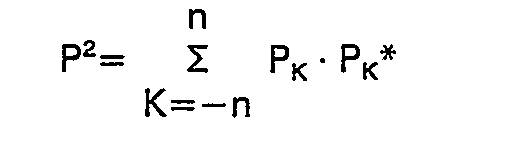
- In the
thired step ③, the normalized data series Xj is supplied to the complex conjugate derivation circuit CN. The derived complex conjugate data series Cj is initialized in the first tap coefficient register TPR1 as the tap coefficient of the first equalization circuit (EQL1) 23. Here, CJ=xJ*=PJ*/P. In the fourth step ④, the normalized data series xj and its complex conjugate data series CJ are supplied to the computing circuit CNT1 of thefirst equalization circuit 23, and the auto-correlation series Am is calculated. The calculation of the auto-correlation series Am is carried out as follows. First, regarding the 0-th order correlation Ao,
- Here, a complex number is expressed in the form of (real component, imaginary component). Regarding the other Am's,

- In the
fifth step ⑤, the auto-correlation series Am is supplied to the computing circuit CNT2 of the second equalization circuit (EQL2) 24, and the first-order approximate series BJ (1) of the inverse characteristic matrix is obtained as follows.
- The series BJ (1) obtained as above is used as the initial condition for obtaining the inverse matrix.
- In the sixth step ⑥, the data series BJ (1) obtained in the
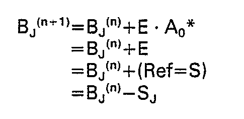
fifth step ⑤ is used as the tap coefficient Bj of the second equalization circuit to calculate the equalized output S with the auto-correlation series Am as the tap data. Then, the output S is compared with the reference output series Ref, and the tap coefficient Bj is corrected successively so as to make the error approach zero. The equalized output S is the data series SL given as follows:
- The correction of the tap coefficient Bj is carried out by using the following successive approximation method:


second equalization circuit 24 is initialized and set in the tap coefficient register TPR2. - After the above-mentioned steps, the initialization of the tap coefficient of the automatic equalization device is completed. Predicting the time when the start-up in the
receiver 2 is completed as described above, thetransmitter 1 starts to transmit the transmission data. In thereceiver 2, the received data signal is demodulated in the data series in thedemodulation unit 21 and supplied to thefirst equalization circuit 23. In thefirst equalization circuit 23, the first equalized output is calculated from the received data series by the first equalized output circuit OPU1 using the tap coefficient CJ in the first tap coefficient register TPR1. The equalized output data series from thefirst equalization circuit 23 is supplied to the equalized output circuit OPU2 of thesecond equalization circuit 24, and the final equalized output data is calculated using the second tap coefficient Bj. By way of reference, it is possible to form a single equalized output circuit for the received data by calculating a combined tap coefficient from the first tap coefficient CJ and the second tap coefficient BJ by a convolution operation. - An automatic equalization device in accordance with one embodiment of the present invention is illustrated in detail in Fig. 5. In Fig. 5, the received signal, after demodulation by the
demodulation unit 21, is equalized by thefirst equalization circuit 23 and thesecond equalization circuit 24. - The equalized output is data discriminated in the
data discrimination unit 25 and then output as output data. On the other hand, during the start-up period, the output signal of thedemodulation unit 21 is supplied to the singlepulse extraction unit 22, and the first andsecond equalization circuits demodulation unit 21 has a filter circuit (FIL) 211 for removing the noise from the received signal, an automatic gain control circuit (AGC) 212 for adjusting the level of the received signal, a demodulation circuit (DEM) 213 for demodulation of the quadrature-amplitude modulation, and a roll-off filter circuit (ROF) 214 for removing the high frequency component from the demodulated signal. The singlepulse extraction unit 22 has an extraction circuit (REP) 221 for extracting the data series corresponding to the single pulse signal from the training signal, a normalization circuit (NR) 222 for normalizing the extracted data series, and a complex conjugate derivation circuit (CN) 223 for deriving the complex conjugate data series of the normalized data series. The first equalization circuit (EQL1) 23 has a first tap data register (TPD1) into which the received data from thedemodulation unit 21 is written, a first equalized output circuit (OPU1) 232 for calculating the first equalized output from the first tap data and the first tap coefficient, a first tap coefficient register (TPR1) 234 which is initially set by the output data of the complexconjugate derivation circuit 223, a first computing control circuit (CNT1) 235 for calculating the auto-correlation series of the single pulse signal, and a second tap data register (TPD2) 236 into which the data series from thenormalization circuit 222 is written. The second equalization circuit (EQL2) 24 has a third tap data register (TPD3) 241 into which the first equalized output data is written, a second equalized output circuit (OPU2) 242 for calculating the second equalized output from the third tap data and the second tap coefficient, a second tap coefficient register (TRP2) 243, a second computing control circuit (CNT2) 244 for calculating the equalized output from the auto-correlation series of the single pulse and the second tap coefficient and for correcting the second tap coefficient in accordance with the error of the equalized output to the reference output Ref, an n-th order approximation circuit (n-th AP) 245 for obtaining the n-th order approximation of the inverse matrix from the auto-correlation series, a fourth tap data register (TPD4) 246 into which the auto-correlation series of the single pulse is written, and an error calculation circuit (EPR2) 247 for calculating the error of the equalized output to the reference output using the auto-correlation series of the single pulse. Thedata discrimination unit 25 has a carrier automatic phase control circuit (CAPC) 251, adiscrimination circuit 252, and an error calculation circuit (ERR1) 253. The circuits in thedata discrimination unit 25 are disclosed, for example, in Japanese Patent No. 1,041,066, thus are not described herein. - In accordance with the above-mentioned method of starting-up the automatic equalization device according to the present invention, by calculation of the symmetric inverse matrix enables reduction of the calculation time of the tap coefficient. For example, it is possible to reduce the time required for a start up compared with the prior art disclosed in the above-mentioned U.S. Patent No. 3,962,637.
- In addition, in accordance with the method of starting-up the automatic equalization device according to the present invention, use of a signal including the carrier signal continuously as the signal for extracting a single pulse enables prevention of asynchronism.
- The present invention can be applied for increasing the data transmission efficiency in a multipoint communication system.
Claims (7)
Applications Claiming Priority (2)
| Application Number | Priority Date | Filing Date | Title |
|---|---|---|---|
| JP214604/81 | 1981-12-28 | ||
| JP56214604A JPS58121838A (en) | 1981-12-28 | 1981-12-28 | Automatic equalizer |
Publications (3)
| Publication Number | Publication Date |
|---|---|
| EP0097723A1 EP0097723A1 (en) | 1984-01-11 |
| EP0097723A4 EP0097723A4 (en) | 1985-09-16 |
| EP0097723B1 true EP0097723B1 (en) | 1988-03-30 |
Family
ID=16658457
Family Applications (1)
| Application Number | Title | Priority Date | Filing Date |
|---|---|---|---|
| EP83900068A Expired EP0097723B1 (en) | 1981-12-28 | 1982-12-28 | Automatic equalizer and method of initialization thereof |
Country Status (6)
| Country | Link |
|---|---|
| US (1) | US4571733A (en) |
| EP (1) | EP0097723B1 (en) |
| JP (1) | JPS58121838A (en) |
| AU (1) | AU546024B2 (en) |
| DE (1) | DE3278305D1 (en) |
| WO (1) | WO1983002373A1 (en) |
Families Citing this family (18)
| Publication number | Priority date | Publication date | Assignee | Title |
|---|---|---|---|---|
| JPS59246A (en) * | 1982-06-17 | 1984-01-05 | Fujitsu Ltd | Training system |
| JPH0619904B2 (en) * | 1983-05-20 | 1994-03-16 | 日本ビクター株式会社 | Waveform processing method for digital signals |
| JPH0614627B2 (en) * | 1985-06-04 | 1994-02-23 | 富士通株式会社 | Modem training methods |
| AU568980B2 (en) * | 1985-06-04 | 1988-01-14 | Fujitsu Limited | Method and device for timing pull-in of receiving equipment |
| US4825448A (en) * | 1986-08-07 | 1989-04-25 | International Mobile Machines Corporation | Subscriber unit for wireless digital telephone system |
| US4811360A (en) * | 1988-01-14 | 1989-03-07 | General Datacomm, Inc. | Apparatus and method for adaptively optimizing equalization delay of data communication equipment |
| DK168750B1 (en) * | 1990-05-01 | 1994-05-30 | Dancall Telecom As | Method of counter distortion in a receiver of signals which has passed a transmission channel |
| JPH06244879A (en) * | 1993-02-19 | 1994-09-02 | Fujitsu Ltd | Modulation and demodulation method using special training pattern |
| US5619503A (en) * | 1994-01-11 | 1997-04-08 | Ericsson Inc. | Cellular/satellite communications system with improved frequency re-use |
| JP3266432B2 (en) * | 1994-12-20 | 2002-03-18 | 富士通株式会社 | Training method in non-Nyquist transmission method and training data transmission device in non-Nyquist transmission method |
| US6185251B1 (en) | 1998-03-27 | 2001-02-06 | Telefonaktiebolaget Lm Ericsson | Equalizer for use in multi-carrier modulation systems |
| JP4311902B2 (en) | 2000-01-07 | 2009-08-12 | アウェア, インコーポレイテッド | System and method for determining transmission line loop length and bridge tap length |
| JP2001313594A (en) * | 2000-04-28 | 2001-11-09 | Fujitsu Ltd | DMT system time domain equalizer coefficient updating method, receiving method, DMT system and DMT modem |
| WO2002067525A2 (en) * | 2001-02-22 | 2002-08-29 | Koninklijke Philips Electronics N.V. | Intercarrier interference cancellation in multicarrier receivers |
| US8406356B2 (en) * | 2007-06-06 | 2013-03-26 | Micron Technology, Inc. | Self-calibrating continuous-time equalization |
| KR101830375B1 (en) * | 2011-06-07 | 2018-02-21 | 한국전자통신연구원 | Device and Method for Receiver of Hybrid Signal |
| US9531569B2 (en) * | 2014-10-08 | 2016-12-27 | Dell Products, Lp | Power aware receiver/transmitter adaptation for high speed serial interfaces |
| US10075286B1 (en) * | 2017-03-13 | 2018-09-11 | Tektronix, Inc. | Equalizer for limited intersymbol interference |
Citations (1)
| Publication number | Priority date | Publication date | Assignee | Title |
|---|---|---|---|---|
| JPS5283010A (en) * | 1975-12-30 | 1977-07-11 | Ibm | Method of determining initial value of complex transversal equalizer factor |
Family Cites Families (5)
| Publication number | Priority date | Publication date | Assignee | Title |
|---|---|---|---|---|
| CH524287A (en) * | 1970-09-25 | 1972-06-15 | Patelhold Patentverwertung | Method for the automatic setting of a transversal filter for pulse equalization |
| US4047013A (en) * | 1975-07-09 | 1977-09-06 | International Business Machines Corporation | Method and apparatus for fast determination of initial transversal equalizer coefficient values |
| JPS5744339A (en) * | 1980-08-29 | 1982-03-12 | Hitachi Ltd | Signal processing system |
| US4430743A (en) * | 1980-11-17 | 1984-02-07 | Nippon Electric Co., Ltd. | Fast start-up system for transversal equalizers |
| JPH05283010A (en) * | 1992-03-31 | 1993-10-29 | Matsushita Electric Ind Co Ltd | Gas discharge type display panel |
-
1981
- 1981-12-28 JP JP56214604A patent/JPS58121838A/en active Granted
-
1982
- 1982-12-28 DE DE8383900068T patent/DE3278305D1/en not_active Expired
- 1982-12-28 WO PCT/JP1982/000479 patent/WO1983002373A1/en not_active Ceased
- 1982-12-28 EP EP83900068A patent/EP0097723B1/en not_active Expired
- 1982-12-28 AU AU10439/83A patent/AU546024B2/en not_active Ceased
- 1982-12-28 US US06/527,573 patent/US4571733A/en not_active Expired - Lifetime
Patent Citations (1)
| Publication number | Priority date | Publication date | Assignee | Title |
|---|---|---|---|---|
| JPS5283010A (en) * | 1975-12-30 | 1977-07-11 | Ibm | Method of determining initial value of complex transversal equalizer factor |
Also Published As
| Publication number | Publication date |
|---|---|
| EP0097723A4 (en) | 1985-09-16 |
| EP0097723A1 (en) | 1984-01-11 |
| DE3278305D1 (en) | 1988-05-05 |
| WO1983002373A1 (en) | 1983-07-07 |
| AU546024B2 (en) | 1985-08-08 |
| US4571733A (en) | 1986-02-18 |
| JPS648498B2 (en) | 1989-02-14 |
| JPS58121838A (en) | 1983-07-20 |
Similar Documents
| Publication | Publication Date | Title |
|---|---|---|
| EP0097723B1 (en) | Automatic equalizer and method of initialization thereof | |
| US5870438A (en) | Fast resynchronization system for high-speed data transmission | |
| US4416015A (en) | Timing acquisition in voiceband data sets | |
| US4621366A (en) | Modem equalizer training using previously stored parameters | |
| EP0204308A2 (en) | Modem communication system having training means and method for training same | |
| EP0496677B1 (en) | Adaptive equalizers | |
| US6535549B1 (en) | Method and apparatus for carrier phase tracking | |
| US4262360A (en) | Method and device for detecting a pseudo-random sequence of carrier phase changes of 0° and 180° in a data receiver | |
| US6363131B1 (en) | Method and apparatus for joint timing synchronization and frequency offset estimation | |
| EP0318684A2 (en) | Rapid reference acquisition and phase error compensation for radio transmission of data | |
| EP0186691A1 (en) | Technique for acquiring timing and frequency synchronization for modem utilizing known (non-data) symbols as part of their normal transmitted data format | |
| US5369668A (en) | Fast response matched filter receiver with decision feedback equalizer | |
| WO1980001348A1 (en) | Synchronization of a data communication receiver with a received signal | |
| US4403331A (en) | Method and apparatus for transmitting data over limited bandwidth channels | |
| CA1291545C (en) | Data modem receiver | |
| US3795865A (en) | Automated real time equalized modem | |
| CN112073116B (en) | Frame structure of satellite carrier superposition signal and demodulation method thereof | |
| US4539689A (en) | Fast learn digital adaptive equalizer | |
| JP3517056B2 (en) | Sampling timing phase error detector for VSB modulated signal | |
| EP0913973A2 (en) | Method and system for joint timing recovery and channel estimation for DMT modems | |
| JPS5938780B2 (en) | How to synchronize digital modems | |
| EP0573696A1 (en) | Timing recovery method and system | |
| EP0205378B1 (en) | Method and device for timing pull-in of receiving equipment | |
| US3479458A (en) | Automatic channel equalization apparatus | |
| US6731710B1 (en) | Method for rapid carrier frequency estimation in a communication system |
Legal Events
| Date | Code | Title | Description |
|---|---|---|---|
| PUAI | Public reference made under article 153(3) epc to a published international application that has entered the european phase |
Free format text: ORIGINAL CODE: 0009012 |
|
| 17P | Request for examination filed |
Effective date: 19830816 |
|
| AK | Designated contracting states |
Designated state(s): DE FR GB NL |
|
| 17Q | First examination report despatched |
Effective date: 19860829 |
|
| GRAA | (expected) grant |
Free format text: ORIGINAL CODE: 0009210 |
|
| AK | Designated contracting states |
Kind code of ref document: B1 Designated state(s): DE FR GB NL |
|
| REF | Corresponds to: |
Ref document number: 3278305 Country of ref document: DE Date of ref document: 19880505 |
|
| ET | Fr: translation filed | ||
| PLBE | No opposition filed within time limit |
Free format text: ORIGINAL CODE: 0009261 |
|
| STAA | Information on the status of an ep patent application or granted ep patent |
Free format text: STATUS: NO OPPOSITION FILED WITHIN TIME LIMIT |
|
| 26N | No opposition filed | ||
| PGFP | Annual fee paid to national office [announced via postgrant information from national office to epo] |
Ref country code: NL Payment date: 19971223 Year of fee payment: 16 |
|
| PGFP | Annual fee paid to national office [announced via postgrant information from national office to epo] |
Ref country code: FR Payment date: 19981209 Year of fee payment: 17 |
|
| PGFP | Annual fee paid to national office [announced via postgrant information from national office to epo] |
Ref country code: GB Payment date: 19981231 Year of fee payment: 17 |
|
| PGFP | Annual fee paid to national office [announced via postgrant information from national office to epo] |
Ref country code: DE Payment date: 19990107 Year of fee payment: 17 |
|
| PG25 | Lapsed in a contracting state [announced via postgrant information from national office to epo] |
Ref country code: NL Free format text: LAPSE BECAUSE OF NON-PAYMENT OF DUE FEES Effective date: 19990701 |
|
| NLV4 | Nl: lapsed or anulled due to non-payment of the annual fee |
Effective date: 19990701 |
|
| PG25 | Lapsed in a contracting state [announced via postgrant information from national office to epo] |
Ref country code: GB Free format text: LAPSE BECAUSE OF NON-PAYMENT OF DUE FEES Effective date: 19991228 |
|
| GBPC | Gb: european patent ceased through non-payment of renewal fee |
Effective date: 19991228 |
|
| PG25 | Lapsed in a contracting state [announced via postgrant information from national office to epo] |
Ref country code: FR Free format text: LAPSE BECAUSE OF NON-PAYMENT OF DUE FEES Effective date: 20000831 |
|
| PG25 | Lapsed in a contracting state [announced via postgrant information from national office to epo] |
Ref country code: DE Free format text: LAPSE BECAUSE OF NON-PAYMENT OF DUE FEES Effective date: 20001003 |
|
| REG | Reference to a national code |
Ref country code: FR Ref legal event code: ST |