EP0097728A1 - Dispositif de serrage ou de préhension du type pince - Google Patents
Dispositif de serrage ou de préhension du type pince Download PDFInfo
- Publication number
- EP0097728A1 EP0097728A1 EP82105609A EP82105609A EP0097728A1 EP 0097728 A1 EP0097728 A1 EP 0097728A1 EP 82105609 A EP82105609 A EP 82105609A EP 82105609 A EP82105609 A EP 82105609A EP 0097728 A1 EP0097728 A1 EP 0097728A1
- Authority
- EP
- European Patent Office
- Prior art keywords
- lever handle
- guide member
- gripping
- lever
- guide
- Prior art date
- Legal status (The legal status is an assumption and is not a legal conclusion. Google has not performed a legal analysis and makes no representation as to the accuracy of the status listed.)
- Withdrawn
Links
Images

Classifications
-
- B—PERFORMING OPERATIONS; TRANSPORTING
- B25—HAND TOOLS; PORTABLE POWER-DRIVEN TOOLS; MANIPULATORS
- B25B—TOOLS OR BENCH DEVICES NOT OTHERWISE PROVIDED FOR, FOR FASTENING, CONNECTING, DISENGAGING, OR HOLDING
- B25B7/00—Pliers; Other hand-held gripping tools with jaws on pivoted limbs; Details applicable generally to pivoted-limb hand tools
- B25B7/06—Joints
- B25B7/10—Joints with adjustable fulcrum
Definitions
- the invention relates to a plier-like clamping or gripping tool with two intersecting, pivotally connected lever handles, each provided with a gripping jaw, the first of which forms a guide, along which to change the width of the jaws formed by the gripping jaws, the second lever handle relative by means of a guide member displaceable to the first lever handle and on which the guide member can be fixed by pivoting the second lever handle in the sense of closing the pliers mouth.
- Pipe wrenches Tools of this type are known as pipe wrenches.
- the gripping jaws are integrally formed on the front ends of the lever handles.
- the part formed by the first lever handle and the associated gripping jaw is cranked below the gripping jaw so that there is a section running approximately perpendicular to the clamping surface of this gripping jaw, in which a guide slot extending in the longitudinal direction of this section is provided.
- the second lever handle is held in this guide slot by means of a pivot pin attached to it. This is on one side flattened, and the guide slot is provided with successive lateral bulges, in the area of which the width of the guide slot corresponds to the full diameter of the pivot pin.
- the invention is now intended to create a tool of the type mentioned at the outset which permits a change in the jaw width not only in steps but also continuously, in a simpler manner than in the known pipe wrenches described.
- This object can be achieved according to the invention in that the guide member can be fixed by tilting on the first lever handle and on which it faces away from the gripping jaws. Side extending and there articulated with the second lever handle lever is formed.
- the first lever handle forms a guide rail for the guide member, and the latter comprises the guide rail at least on the latter facing the gripping jaws and on the opposite side in such a way that the guide member can be fixed on the guide rail by pivoting it in the sense of closing the pliers mouth by tilting it relative to the latter.
- the gripping tool according to the invention can belong to the second lever handle Gripper jaw can be moved quickly and easily to the object to be clamped, so that it can always be clamped with parallel gripper jaw clamping surfaces. There is also no longer the annoying repeated opening and adjustment of the tool known to each user of the pipe wrenches described in order to adapt it to the dimensions of the object to be clamped.
- the tool according to the invention even allows one-hand operation, since it is easily possible to grasp the two lever handles with the fingers of one hand so that the second lever handle can be moved relative to the first by To change the jaw width, which is then tightened by pressing the two lever handles together.
- the gripping jaws can be levered be formed in one piece, in a preferred embodiment, however, the gripping jaw of the first lever handle is produced as a separate part and then connected to the lever handle, for example by pressing and caulking, in which case a profile rail is advantageously used for this first lever handle, as is the case with clamping tools such as screw clamps and the like is known.
- the second lever handle runs approximately parallel to the first lever handle when the pliers jaw is closed and is bent approximately at right angles to its gripping jaw - normally the gripping jaw of the first lever handle also becomes the region of the first lever adjacent to this gripping jaw g riffs form at least approximately a right angle.
- the second lever handle or its gripping jaw can strike either on the first lever handle or on the guide member.
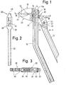
- Fig. 1 shows a first lever handle lo, which was made from a standard steel profile used for known clamping tools such as screw clamps and at the upper end of which a first gripping jaw 12 is attached. This has an opening 14 into which the lever handle lo was pressed and then caulked (riveted) at 16, so that there was a firm connection between lever handle lo and gripping jaw 12.
- 18 designated and conventionally designed clamping surface 18 of the first gripping jaw 12 extends approximately perpendicular to the upper region of the lever handle 10, which according to the invention is approximately angled backwards in its center.
- a second gripping jaw is 2o integrally formed on a second lever handle 22, and of these two elements g e-formed part has an opening 24 which is delimited laterally by edges 26 and 28; these will, as will be explained later, act as stops and are therefore referred to below as stop edges.
- a lever-shaped guide element 3o is articulated on the lever handle 22 in the region of the opening 24 with the aid of a joint pin 32.
- This guide member extends from its articulation point in the direction of the first lever handle 10 and over the second lever handle 22 and it has a guide opening 36 which, together with the opening 24 of the lever handle 22, allows the assembly consisting of lever handle 22 and guide member 30 can be pushed onto the first lever handle lo from below.
- An upper, lateral edge 36a and a lower lateral edge 36b of the guide opening 36 cause the guide member 3o to pivot when the guide member 3o is pivoted in the direction of arrow B (see FIG. 1) relative to the first lever handle 10o tilted on the lever handle lo and can no longer be moved on it.
- the stop edge 26 together with the first lever handle lo now limits the opening angle of the tool, while the stop edge 28 together with an edge 42 of the guide element 3o causes the guide element 3o according to FIG. 1 to pivot against the arrow B when opening the pliers and thereby the tilt on the first lever handle lo is released.
- FIG. 4 Since the embodiment according to FIG. 4 is similar in many design features to the first embodiment, the same reference numerals have been used, but with the addition of a dash, and only those features are explained below in which this second, preferred embodiment differs from the first embodiment 1 to 3 differs.
- the guide member 30 below the second gripping jaw 2o ', in such a way that the edges 36a' and 36b 'responsible for fixing the guide member 3o' lie below the line 5o 'which defines the axis of the pivot pin 32' with the front ends of the clamping surfaces 18 'and 4o 'connects.
- This measure ensures that the canting of the guide member 30 'on the first lever handle 10' is not reduced if an object clamped with the tool according to the invention is to be rotated counterclockwise according to FIG. 4.
- the second lever handle 22 ' is bent in the region 6 0 ' in such a way that, as a comparison of FIGS. 1 and 4 shows, the preferred embodiment according to FIG. 4 is narrower than the embodiment according to FIG. 1 to 3.
- the opening angle of the pliers is limited according to the invention in the second embodiment in that the gripping jaw 2 0 'of the second lever handle 22' abuts against the guide member 30 ', which advantageously also releases the canting (see the position of the lever handle 22' shown in broken lines).
Landscapes
- Engineering & Computer Science (AREA)
- Mechanical Engineering (AREA)
- Gripping Jigs, Holding Jigs, And Positioning Jigs (AREA)
Priority Applications (1)
| Application Number | Priority Date | Filing Date | Title |
|---|---|---|---|
| EP82105609A EP0097728A1 (fr) | 1982-06-25 | 1982-06-25 | Dispositif de serrage ou de préhension du type pince |
Applications Claiming Priority (1)
| Application Number | Priority Date | Filing Date | Title |
|---|---|---|---|
| EP82105609A EP0097728A1 (fr) | 1982-06-25 | 1982-06-25 | Dispositif de serrage ou de préhension du type pince |
Publications (1)
| Publication Number | Publication Date |
|---|---|
| EP0097728A1 true EP0097728A1 (fr) | 1984-01-11 |
Family
ID=8189101
Family Applications (1)
| Application Number | Title | Priority Date | Filing Date |
|---|---|---|---|
| EP82105609A Withdrawn EP0097728A1 (fr) | 1982-06-25 | 1982-06-25 | Dispositif de serrage ou de préhension du type pince |
Country Status (1)
| Country | Link |
|---|---|
| EP (1) | EP0097728A1 (fr) |
Cited By (1)
| Publication number | Priority date | Publication date | Assignee | Title |
|---|---|---|---|---|
| WO2005115691A1 (fr) * | 2004-05-11 | 2005-12-08 | Knipex-Werk C. Gustav Putsch Kg. | Pince reglable |
Citations (4)
| Publication number | Priority date | Publication date | Assignee | Title |
|---|---|---|---|---|
| US2831385A (en) * | 1956-03-29 | 1958-04-22 | Paul O Tobeler | Pincers having adjustable jaws with locking pinion |
| US3142212A (en) * | 1963-03-12 | 1964-07-28 | Leonard E Grape | Pliers |
| DE2204386A1 (de) * | 1972-01-31 | 1973-08-09 | Guenther Dr Ing Schick | Zange mit veraenderbarer greifweite |
| US4048878A (en) * | 1976-04-05 | 1977-09-20 | Dresser Industries, Inc. | Slip-type pliers tool |
-
1982
- 1982-06-25 EP EP82105609A patent/EP0097728A1/fr not_active Withdrawn
Patent Citations (4)
| Publication number | Priority date | Publication date | Assignee | Title |
|---|---|---|---|---|
| US2831385A (en) * | 1956-03-29 | 1958-04-22 | Paul O Tobeler | Pincers having adjustable jaws with locking pinion |
| US3142212A (en) * | 1963-03-12 | 1964-07-28 | Leonard E Grape | Pliers |
| DE2204386A1 (de) * | 1972-01-31 | 1973-08-09 | Guenther Dr Ing Schick | Zange mit veraenderbarer greifweite |
| US4048878A (en) * | 1976-04-05 | 1977-09-20 | Dresser Industries, Inc. | Slip-type pliers tool |
Cited By (1)
| Publication number | Priority date | Publication date | Assignee | Title |
|---|---|---|---|---|
| WO2005115691A1 (fr) * | 2004-05-11 | 2005-12-08 | Knipex-Werk C. Gustav Putsch Kg. | Pince reglable |
Similar Documents
| Publication | Publication Date | Title |
|---|---|---|
| DE69408242T2 (de) | Verbesserungen in Bezug auf Drahtentmantelungswerkzeuge | |
| DE3913615A1 (de) | Verstellbarer schraubenschluessel | |
| EP1319456A1 (fr) | Découpeur de câbles | |
| DE3813342A1 (de) | Klemmeinrichtung | |
| DE10351224A1 (de) | Klemmen-Handwerkzeug | |
| DE3202036C2 (fr) | ||
| DE2749025A1 (de) | Einstellbare spannzange | |
| DE2749342A1 (de) | Werkzeug zum spannen und schneiden von selbstverriegelungsbaendern | |
| DE3023882A1 (de) | Vorrichtung zur betaetigung von handwerkzeugen | |
| EP0824996B1 (fr) | Pince à ouverture variable | |
| DE29914764U1 (de) | Zange | |
| DE102016125517B4 (de) | Handwerkzeug mit einer Ratschenfunktion | |
| DE4424493C2 (de) | Zangenartiges Werkzeug zum formschlüssigen Verbinden von Blechteilen | |
| DE19524294C2 (de) | Rohrschelle | |
| EP0097728A1 (fr) | Dispositif de serrage ou de préhension du type pince | |
| DE3139052A1 (de) | Vorrichtung zum aufbrechen von nuessen o.dgl. | |
| EP0074487B1 (fr) | Dispositif de serrage | |
| DE3152016C2 (de) | Spannwerkzeug mit einer Gleitschiene, insbes. in Verbindung mit einer Gripzange oder Gripzwinge | |
| DE4128887A1 (de) | Gripzange | |
| DE69400910T2 (de) | Werkzeug versehen mit einer markiervorrichtung | |
| DE3118528A1 (de) | Zangenartiges klemm- oder greifwerkzeug | |
| DE102005010464B4 (de) | Greifzange | |
| DE20101112U1 (de) | Schraubenschlüssel | |
| DE29803998U1 (de) | Zange | |
| DE10044874A1 (de) | Schlüsselzange |
Legal Events
| Date | Code | Title | Description |
|---|---|---|---|
| PUAI | Public reference made under article 153(3) epc to a published international application that has entered the european phase |
Free format text: ORIGINAL CODE: 0009012 |
|
| AK | Designated contracting states |
Designated state(s): AT CH FR IT LI |
|
| STAA | Information on the status of an ep patent application or granted ep patent |
Free format text: STATUS: THE APPLICATION IS DEEMED TO BE WITHDRAWN |
|
| 18D | Application deemed to be withdrawn |
Effective date: 19840912 |
|
| RIN1 | Information on inventor provided before grant (corrected) |
Inventor name: ROESCH, HANS Inventor name: KLIMACH, HORST, ING. GRAD. |