EP0097739A1 - Dispositif d'appui hydraulique - Google Patents
Dispositif d'appui hydraulique Download PDFInfo
- Publication number
- EP0097739A1 EP0097739A1 EP82200815A EP82200815A EP0097739A1 EP 0097739 A1 EP0097739 A1 EP 0097739A1 EP 82200815 A EP82200815 A EP 82200815A EP 82200815 A EP82200815 A EP 82200815A EP 0097739 A1 EP0097739 A1 EP 0097739A1
- Authority
- EP
- European Patent Office
- Prior art keywords
- piston rod
- brake
- cylinder
- piston
- pressure
- Prior art date
- Legal status (The legal status is an assumption and is not a legal conclusion. Google has not performed a legal analysis and makes no representation as to the accuracy of the status listed.)
- Granted
Links
- 230000000903 blocking effect Effects 0.000 claims abstract description 12
- 238000006073 displacement reaction Methods 0.000 claims description 3
- 239000012530 fluid Substances 0.000 description 6
- 230000005540 biological transmission Effects 0.000 description 1
- 238000010276 construction Methods 0.000 description 1
- 230000002950 deficient Effects 0.000 description 1
- 230000000694 effects Effects 0.000 description 1
- 230000002349 favourable effect Effects 0.000 description 1
- 230000008439 repair process Effects 0.000 description 1
- 230000000284 resting effect Effects 0.000 description 1
- 238000007789 sealing Methods 0.000 description 1
- 230000035939 shock Effects 0.000 description 1
Images
Classifications
-
- F—MECHANICAL ENGINEERING; LIGHTING; HEATING; WEAPONS; BLASTING
- F41—WEAPONS
- F41A—FUNCTIONAL FEATURES OR DETAILS COMMON TO BOTH SMALLARMS AND ORDNANCE, e.g. CANNONS; MOUNTINGS FOR SMALLARMS OR ORDNANCE
- F41A23/00—Gun mountings, e.g. on vehicles; Disposition of guns on vehicles
- F41A23/50—Travelling locks; Brakes for holding the gun platform in a fixed position during transport
-
- B—PERFORMING OPERATIONS; TRANSPORTING
- B66—HOISTING; LIFTING; HAULING
- B66C—CRANES; LOAD-ENGAGING ELEMENTS OR DEVICES FOR CRANES, CAPSTANS, WINCHES, OR TACKLES
- B66C23/00—Cranes comprising essentially a beam, boom, or triangular structure acting as a cantilever and mounted for translatory of swinging movements in vertical or horizontal planes or a combination of such movements, e.g. jib-cranes, derricks, tower cranes
- B66C23/62—Constructional features or details
- B66C23/72—Counterweights or supports for balancing lifting couples
- B66C23/78—Supports, e.g. outriggers, for mobile cranes
- B66C23/80—Supports, e.g. outriggers, for mobile cranes hydraulically actuated
-
- F—MECHANICAL ENGINEERING; LIGHTING; HEATING; WEAPONS; BLASTING
- F15—FLUID-PRESSURE ACTUATORS; HYDRAULICS OR PNEUMATICS IN GENERAL
- F15B—SYSTEMS ACTING BY MEANS OF FLUIDS IN GENERAL; FLUID-PRESSURE ACTUATORS, e.g. SERVOMOTORS; DETAILS OF FLUID-PRESSURE SYSTEMS, NOT OTHERWISE PROVIDED FOR
- F15B15/00—Fluid-actuated devices for displacing a member from one position to another; Gearing associated therewith
- F15B15/20—Other details, e.g. assembly with regulating devices
- F15B15/26—Locking mechanisms
- F15B15/262—Locking mechanisms using friction, e.g. brake pads
-
- F—MECHANICAL ENGINEERING; LIGHTING; HEATING; WEAPONS; BLASTING
- F41—WEAPONS
- F41A—FUNCTIONAL FEATURES OR DETAILS COMMON TO BOTH SMALLARMS AND ORDNANCE, e.g. CANNONS; MOUNTINGS FOR SMALLARMS OR ORDNANCE
- F41A23/00—Gun mountings, e.g. on vehicles; Disposition of guns on vehicles
- F41A23/56—Arrangements for adjusting the gun platform in the vertical or horizontal position
Definitions
- the invention relates to a hydraulic support device for vehicles, in particular self-propelled guns, which consists of a plurality of double-acting hydraulic cylinders which are fastened vertically to the chassis and whose piston rods form support feet.
- a safety device for lifts, lifts and. Like., which are raised by means of hydraulic piston rods
- a safety device is known from DE-A 23 33 491, in which a plurality of brake shoes resting against the piston rod and under spring tension are provided to block the piston rod in the event of an undesired pressure drop in the working medium inclined guideways of a housing part are mounted. If there is an undesirable drop in pressure, the brake shoes are pressed in a wedge shape between the guideways and the piston rod and block the piston rod by friction. Hydraulic drives of the type of working cylinders are provided to release the safety gear, which can be actuated via a special hydraulic control line and push back the brake shoes.
- Safety devices of this type that only serve the safety of people are also not suitable for hydraulic support devices of vehicles. The additional hydraulic control line with several working cylinders is also complicated to set up and prone to failure.
- the invention has for its object to provide a hydraulic support device for vehicles of the generic type in such a way that without maintaining the pressure of the hydraulic equipment with simple means blocking the extended piston rod and in Connection with the retraction of the piston rod enables a quick release.
- the piston rods are provided with brake shoes which rest against their jacket and are effective in the direction of retraction, which are supported on oblique guide surfaces of a brake housing, are pressed by springs in the direction of retraction and to release them are guided on the piston rod and in the axial direction against the brake shoes displaceable pressure sleeve is provided with an annular projection which is arranged in an annular chamber connecting the rod-side cylinder chamber with the associated pressure line.
- the hydraulic support device initially has the advantage that the piston rod is locked in its position in an extended position solely by mechanical means.
- the support device has a compact structure, the components provided for blocking and releasing being arranged in a protected manner in a brake housing which is arranged at the lower end of the hydraulic cylinder and there also stores the piston rod in the blocked position in the horizontal direction, so that a particularly favorable transmission of forces takes place.
- the blocking device is advantageously released automatically when the piston rods pass through Actuation of the hydraulic system is retracted.
- the device for releasing the blocking advantageously uses the hydraulic system that is present anyway for retracting the piston rod. A special hydraulic control line for unblocking is therefore not necessary.
- the working hours for extending and retracting the piston rods are particularly short, so that a quick change of location is made easier, especially with self-propelled guns.
- the brake housing is expediently provided with a stop shoulder which limits the axial displacement of the pressure sleeve in a position which releases the brake shoes. This fixes the pressure sleeve and the pressure energy of the working fluid can only be used to retract the piston rod.
- the pressure sleeve can be provided with a collar which blocks a ring-shaped inflow opening of the rod-side cylinder chamber in the blocking position in whole or in part and releases it when it stops against the stop shoulder . The pressure sleeve then also acts like a valve.
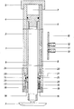
- a hydraulic cylinder 1 of a hydraulic support device is shown in a longitudinal section.
- a vehicle is generally assigned several, preferably four, hydraulic cylinders which can be actuated simultaneously or independently of one another depending on the hydraulic control circuit.
- Each hydraulic cylinder 1 is directly on the chassis of a vehicle, e.g. a self-propelled gun, vertically and preferably releasably attached.
- a support device can not only be used for combat support while relieving the entire chassis of self-propelled guns, but also serves to lift the vehicle, e.g. Tire change, repairs to the chassis or the like.
- a piston rod 2 is arranged, at the lower end of which a support leg 3 is articulated.
- a cover 5 is attached to the head end.
- the associated piston 4 separates a piston-side cylinder chamber 7 connected to a pressure line 6 from a rod-side cylinder chamber 9 which is connected to a pressure line 8.
- Both pressure lines 6, 8 form channels in the cylinder housing, which have 1 connection openings approximately halfway up the cylinder.
- a connection plate 10 attached to the chassis serves both to fasten the cylinder 1 and to connect supply lines for the hydraulic working fluid.
- connection plate 10 The attachment of the cylinder 1 to the connecting plate 10 is conveniently done by detachable screws, so that a quick release of the cylinder unit is possible, be it to replace it or to make the vehicle quickly drivable, for example if the supply lines or the pump of the hydraulic Systems are defective, and therefore the piston rod cannot be released.
- two valves 11 are arranged, which are automatically opened when the cylinder 1 is fastened.
- For the supply lines are provided on the connection plate 10 with internally threaded connection sockets 12, 13.
- a cylindrical brake housing 14 is attached, e.g. screwed on by means of a sleeve, through the base plate 15 of which the piston rod is guided.
- a plurality of segment-like brake shoes 16 are arranged above the base plate 15, the inner surface of which has a friction surface 17, while its outer surface tapers conically upwards and interacts with an oblique guide surface 18 in the brake housing 14.
- Each brake shoe 16 has a spring 19 which is supported on the base plate 15 and presses the brake shoe 16 upwards against the oblique guide surface 18, so that the brake shoe 16 is pressed with its friction surface 18 against the jacket of the piston rod 2 as a result of the wedge action is blocked in this way by frictional engagement against axial displacement.
- the spring force is selected so that the frictional engagement is also sufficient to hold the retracted piston rod 2 in the retracted position when the hydraulic system is depressurized.
- a pressure sleeve 20 is arranged above the brake shoes 16, which is axially displaceably mounted on the piston rod 2 and in the brake housing 14, sealing rings and conventional wiper rings being provided with respect to both components.
- the pressure sleeve 20 has an annular extension 21 on its circumference, which projects into an annular chamber 22 of the brake housing 14. This annular chamber 22 also connects the rod-side cylinder chamber 9 to the associated pressure line 8.
- the pressure sleeve is provided with a collar 23 which engages in a valve-like manner in the annular inflow opening 24 of the rod-side cylinder chamber 9.
- a stop shoulder 25 is provided on the brake housing 14 at a height such that the collar 23 clears the annular inflow opening 24 in the stop position.
- the pressure line 8 assigned to the rod-side cylinder chamber 9 is acted upon by the hydraulic working fluid. Since the inflow opening 24 is completely or partially closed by the collar 23, the pressure acts on the annular projection 21 and presses the pressure sleeve 20 downward against the brake shoes 16, which thereby lose their frictional engagement with the piston rod 2. If the pressure sleeve 20 is guided up to the stop shoulder 25, the inflow opening 24 is also free, so that the pressure of the working medium acts on the piston 4 on the rod side and the piston rod 2 retracts. If the pressure of the working medium is released, the springs 19 press the brake shoes 16 into their blocking position, the pressure sleeve 20 also being returned to an upper starting position.
- the blocking system is otherwise designed so that the vertical forces acting on the extended support device increase the effect of the frictional engagement caused by the springs 19.
- the components for blocking and releasing the piston rod can alternatively also be designed differently.
- the annular chamber 22 and the rod-side cylinder chamber 9 can be separated from one another and receive separate connecting lines for the working fluid.
- the collar 23 can be dispensed with even if the pressure area of the attachment 21 is sufficiently large.
Landscapes
- Engineering & Computer Science (AREA)
- General Engineering & Computer Science (AREA)
- Mechanical Engineering (AREA)
- Physics & Mathematics (AREA)
- Fluid Mechanics (AREA)
- Braking Arrangements (AREA)
- Blow-Moulding Or Thermoforming Of Plastics Or The Like (AREA)
Priority Applications (4)
| Application Number | Priority Date | Filing Date | Title |
|---|---|---|---|
| AT82200815T ATE20486T1 (de) | 1982-06-30 | 1982-06-30 | Hydraulische abstuetzvorrichtung. |
| EP82200815A EP0097739B1 (fr) | 1982-06-30 | 1982-06-30 | Dispositif d'appui hydraulique |
| DE8282200815T DE3271763D1 (en) | 1982-06-30 | 1982-06-30 | Hydraulic support arrangements |
| DE19828218955U DE8218955U1 (de) | 1982-06-30 | 1982-07-02 | Hydraulische abstuetzvorrichtung fuer fahrzeuge, insbesondere selbstfahrlafetten |
Applications Claiming Priority (1)
| Application Number | Priority Date | Filing Date | Title |
|---|---|---|---|
| EP82200815A EP0097739B1 (fr) | 1982-06-30 | 1982-06-30 | Dispositif d'appui hydraulique |
Publications (2)
| Publication Number | Publication Date |
|---|---|
| EP0097739A1 true EP0097739A1 (fr) | 1984-01-11 |
| EP0097739B1 EP0097739B1 (fr) | 1986-06-18 |
Family
ID=8189502
Family Applications (1)
| Application Number | Title | Priority Date | Filing Date |
|---|---|---|---|
| EP82200815A Expired EP0097739B1 (fr) | 1982-06-30 | 1982-06-30 | Dispositif d'appui hydraulique |
Country Status (3)
| Country | Link |
|---|---|
| EP (1) | EP0097739B1 (fr) |
| AT (1) | ATE20486T1 (fr) |
| DE (2) | DE3271763D1 (fr) |
Cited By (9)
| Publication number | Priority date | Publication date | Assignee | Title |
|---|---|---|---|---|
| DE3521298A1 (de) * | 1985-06-13 | 1986-12-18 | Applied Power, Inc., Milwaukee, Wis. | Klemmeinrichtung |
| DE3811225A1 (de) * | 1988-04-02 | 1989-10-12 | Sitema | Hydraulische stuetzvorrichtung |
| DE3900344A1 (de) * | 1989-01-07 | 1990-07-12 | Montan Hydraulik Gmbh & Co Kg | Einstufiger zylinder mit kolbenstangen-klemmvorrichtung |
| EP1310077B1 (fr) * | 2000-08-15 | 2008-01-09 | Viaquo Corporation | Procede et appareil pour modele de service applicatif de gestion de securite faisant appel au web |
| CN102678664A (zh) * | 2012-05-31 | 2012-09-19 | 齐齐哈尔轨道交通装备有限责任公司 | 液压支撑油缸及起重机 |
| CN104843432A (zh) * | 2015-04-30 | 2015-08-19 | 北京航天发射技术研究所 | 传力导向装置 |
| CN106744371A (zh) * | 2016-12-13 | 2017-05-31 | 刘国彬 | 一种带二级同步水平伸缩支腿的汽车起重机 |
| CN110439875B (zh) * | 2019-06-28 | 2020-12-25 | 武汉船用机械有限责任公司 | 用于控制负载的液压油缸 |
| EP3926105A1 (fr) * | 2020-06-18 | 2021-12-22 | Hiab AB | Agencement de pied stabilisateur et machine de travail mobile comportant un tel agencement de pied stabilisateur |
Families Citing this family (2)
| Publication number | Priority date | Publication date | Assignee | Title |
|---|---|---|---|---|
| AT387U1 (de) * | 1994-07-01 | 1995-09-25 | Palfinger Ag | Hydraulisch aus- und einfahrbare stuetze fuer ein mit einem ladekran versehenes lastfahrzeug |
| CN104154814B (zh) * | 2014-05-19 | 2016-06-29 | 北京航天发射技术研究所 | 具有自锁功能的拉绳式自动锁筒机构 |
Citations (5)
| Publication number | Priority date | Publication date | Assignee | Title |
|---|---|---|---|---|
| DE943574C (de) * | 1954-07-17 | 1956-05-24 | Walter Ruf | Panzerwagen mit einzeln bedienbaren, verlaenger- und verkuerzbaren Stuetzen |
| FR1131204A (fr) * | 1955-09-08 | 1957-02-19 | Meudon Forges Atel | Cylindre à fluide comprimé à dispositif de sécurité |
| DE1751159A1 (de) * | 1968-04-13 | 1971-04-22 | Rudolf Geiger Praez S Dreh Und | Pneumatische Lineareinheit |
| US3662649A (en) * | 1970-03-23 | 1972-05-16 | Us Army | Self-locking hydraulic linkage |
| DE2333491A1 (de) * | 1973-06-30 | 1975-01-23 | Adolf Rastetter | Fangvorrichtung fuer hydraulisch anhebbare kolbenstangen |
-
1982
- 1982-06-30 EP EP82200815A patent/EP0097739B1/fr not_active Expired
- 1982-06-30 DE DE8282200815T patent/DE3271763D1/de not_active Expired
- 1982-06-30 AT AT82200815T patent/ATE20486T1/de active
- 1982-07-02 DE DE19828218955U patent/DE8218955U1/de not_active Expired
Patent Citations (5)
| Publication number | Priority date | Publication date | Assignee | Title |
|---|---|---|---|---|
| DE943574C (de) * | 1954-07-17 | 1956-05-24 | Walter Ruf | Panzerwagen mit einzeln bedienbaren, verlaenger- und verkuerzbaren Stuetzen |
| FR1131204A (fr) * | 1955-09-08 | 1957-02-19 | Meudon Forges Atel | Cylindre à fluide comprimé à dispositif de sécurité |
| DE1751159A1 (de) * | 1968-04-13 | 1971-04-22 | Rudolf Geiger Praez S Dreh Und | Pneumatische Lineareinheit |
| US3662649A (en) * | 1970-03-23 | 1972-05-16 | Us Army | Self-locking hydraulic linkage |
| DE2333491A1 (de) * | 1973-06-30 | 1975-01-23 | Adolf Rastetter | Fangvorrichtung fuer hydraulisch anhebbare kolbenstangen |
Cited By (10)
| Publication number | Priority date | Publication date | Assignee | Title |
|---|---|---|---|---|
| DE3521298A1 (de) * | 1985-06-13 | 1986-12-18 | Applied Power, Inc., Milwaukee, Wis. | Klemmeinrichtung |
| DE3811225A1 (de) * | 1988-04-02 | 1989-10-12 | Sitema | Hydraulische stuetzvorrichtung |
| DE3900344A1 (de) * | 1989-01-07 | 1990-07-12 | Montan Hydraulik Gmbh & Co Kg | Einstufiger zylinder mit kolbenstangen-klemmvorrichtung |
| EP0377898A1 (fr) * | 1989-01-07 | 1990-07-18 | Montanhydraulik GmbH | Vérin à un étage avec dispositif de verrouillage pour la tige |
| EP1310077B1 (fr) * | 2000-08-15 | 2008-01-09 | Viaquo Corporation | Procede et appareil pour modele de service applicatif de gestion de securite faisant appel au web |
| CN102678664A (zh) * | 2012-05-31 | 2012-09-19 | 齐齐哈尔轨道交通装备有限责任公司 | 液压支撑油缸及起重机 |
| CN104843432A (zh) * | 2015-04-30 | 2015-08-19 | 北京航天发射技术研究所 | 传力导向装置 |
| CN106744371A (zh) * | 2016-12-13 | 2017-05-31 | 刘国彬 | 一种带二级同步水平伸缩支腿的汽车起重机 |
| CN110439875B (zh) * | 2019-06-28 | 2020-12-25 | 武汉船用机械有限责任公司 | 用于控制负载的液压油缸 |
| EP3926105A1 (fr) * | 2020-06-18 | 2021-12-22 | Hiab AB | Agencement de pied stabilisateur et machine de travail mobile comportant un tel agencement de pied stabilisateur |
Also Published As
| Publication number | Publication date |
|---|---|
| DE3271763D1 (en) | 1986-07-24 |
| EP0097739B1 (fr) | 1986-06-18 |
| DE8218955U1 (de) | 1982-10-14 |
| ATE20486T1 (de) | 1986-07-15 |
Similar Documents
| Publication | Publication Date | Title |
|---|---|---|
| DE3118449C2 (fr) | ||
| DE3150643C2 (fr) | ||
| DE974199C (de) | Strebwanderausbaugespann | |
| DE3525101A1 (de) | Prallbrecher | |
| DE29824453U1 (de) | Kran mit einem Teleskopausleger | |
| EP0097739A1 (fr) | Dispositif d'appui hydraulique | |
| DE19824671A1 (de) | Kran mit einem Teleskopausleger | |
| DE3831459A1 (de) | Feststellvorrichtung fuer doppeltwirkende fluidzylinder, insbesondere hydrozylinder | |
| DE2158977B2 (de) | Ausfahrbare Sperre zum vorübergehenden Absperren von Straßen, Plätzen od.dgl | |
| DE1292604B (de) | Hydraulischer Grubenstempel | |
| DE4030167C2 (fr) | ||
| DE2154631C3 (de) | Überlastungsschutzvorrichtung für einen Ladekran | |
| DE3626621C1 (en) | Arrangement for the emergency operation of supporting systems | |
| DE3307644A1 (de) | Druckmittelbetaetiger arbeitszylinder mit verriegelung in beliebiger stellungen | |
| DE3003689A1 (de) | Teleskopausleger fuer krane | |
| DE1268804B (de) | Teleskopausleger | |
| EP0478841A1 (fr) | Vérin télescopique hydraulique pour camion à benne basculante | |
| DE8812882U1 (de) | Druckluftzylinder mit Endlageverriegelung, insbesondere zur Betätigung von Rauchabzugsklappen | |
| DE2143712A1 (de) | Druckmittelbetaetigbarer arbeitszylinder mit endstellungsarretierung | |
| DE6607298U (de) | Sperrvorrichtung in form einer spreizringbremse fuer hydraulisch oder pneumatisch betaetigte verstellaggregate | |
| DE4108274A1 (de) | Teleskopzylinder | |
| DE1169780B (de) | Hydraulischer Stellzylinder mit Verriegelungs-einrichtung | |
| DE3438892C2 (fr) | ||
| EP0116657B1 (fr) | Train d'atterrissage rétractable pour avion | |
| DD147252A5 (de) | Kippbarer konverter |
Legal Events
| Date | Code | Title | Description |
|---|---|---|---|
| PUAI | Public reference made under article 153(3) epc to a published international application that has entered the european phase |
Free format text: ORIGINAL CODE: 0009012 |
|
| 17P | Request for examination filed |
Effective date: 19830603 |
|
| AK | Designated contracting states |
Designated state(s): AT BE CH DE FR GB IT LI LU NL SE |
|
| ITF | It: translation for a ep patent filed | ||
| GRAA | (expected) grant |
Free format text: ORIGINAL CODE: 0009210 |
|
| AK | Designated contracting states |
Kind code of ref document: B1 Designated state(s): AT BE CH DE FR GB IT LI LU NL SE |
|
| REF | Corresponds to: |
Ref document number: 20486 Country of ref document: AT Date of ref document: 19860715 Kind code of ref document: T |
|
| PG25 | Lapsed in a contracting state [announced via postgrant information from national office to epo] |
Ref country code: LU Free format text: LAPSE BECAUSE OF NON-PAYMENT OF DUE FEES Effective date: 19860630 |
|
| REF | Corresponds to: |
Ref document number: 3271763 Country of ref document: DE Date of ref document: 19860724 |
|
| ET | Fr: translation filed | ||
| PLBE | No opposition filed within time limit |
Free format text: ORIGINAL CODE: 0009261 |
|
| STAA | Information on the status of an ep patent application or granted ep patent |
Free format text: STATUS: NO OPPOSITION FILED WITHIN TIME LIMIT |
|
| 26N | No opposition filed | ||
| PGFP | Annual fee paid to national office [announced via postgrant information from national office to epo] |
Ref country code: SE Payment date: 19890516 Year of fee payment: 8 |
|
| PGFP | Annual fee paid to national office [announced via postgrant information from national office to epo] |
Ref country code: CH Payment date: 19890523 Year of fee payment: 8 |
|
| PGFP | Annual fee paid to national office [announced via postgrant information from national office to epo] |
Ref country code: FR Payment date: 19890530 Year of fee payment: 8 |
|
| PGFP | Annual fee paid to national office [announced via postgrant information from national office to epo] |
Ref country code: LU Payment date: 19890628 Year of fee payment: 8 |
|
| ITTA | It: last paid annual fee | ||
| PGFP | Annual fee paid to national office [announced via postgrant information from national office to epo] |
Ref country code: NL Payment date: 19890630 Year of fee payment: 8 Ref country code: GB Payment date: 19890630 Year of fee payment: 8 Ref country code: AT Payment date: 19890630 Year of fee payment: 8 |
|
| PGFP | Annual fee paid to national office [announced via postgrant information from national office to epo] |
Ref country code: BE Payment date: 19890802 Year of fee payment: 8 |
|
| PG25 | Lapsed in a contracting state [announced via postgrant information from national office to epo] |
Ref country code: LI Effective date: 19900630 Ref country code: GB Effective date: 19900630 Ref country code: CH Effective date: 19900630 Ref country code: BE Effective date: 19900630 Ref country code: AT Effective date: 19900630 |
|
| PG25 | Lapsed in a contracting state [announced via postgrant information from national office to epo] |
Ref country code: SE Effective date: 19900701 |
|
| BERE | Be: lapsed |
Owner name: HYDRO-GERATEBAU G.M.B.H. & CO. K.G. HEBEZEUGE Effective date: 19900630 |
|
| PG25 | Lapsed in a contracting state [announced via postgrant information from national office to epo] |
Ref country code: NL Effective date: 19910101 |
|
| NLV4 | Nl: lapsed or anulled due to non-payment of the annual fee | ||
| GBPC | Gb: european patent ceased through non-payment of renewal fee | ||
| PG25 | Lapsed in a contracting state [announced via postgrant information from national office to epo] |
Ref country code: FR Effective date: 19910228 |
|
| REG | Reference to a national code |
Ref country code: CH Ref legal event code: PL |
|
| REG | Reference to a national code |
Ref country code: FR Ref legal event code: ST |
|
| PGFP | Annual fee paid to national office [announced via postgrant information from national office to epo] |
Ref country code: DE Payment date: 19930604 Year of fee payment: 12 |
|
| EUG | Se: european patent has lapsed |
Ref document number: 82200815.7 Effective date: 19910402 |
|
| PG25 | Lapsed in a contracting state [announced via postgrant information from national office to epo] |
Ref country code: DE Effective date: 19950301 |