EP0097756A2 - Magnetisierbarer Eisenkern zur Unterbringung elektrischer Leiter in einer elektrischen Maschine und ein Verfahren zur Herstellung solch eines Kernes - Google Patents
Magnetisierbarer Eisenkern zur Unterbringung elektrischer Leiter in einer elektrischen Maschine und ein Verfahren zur Herstellung solch eines Kernes Download PDFInfo
- Publication number
- EP0097756A2 EP0097756A2 EP82850220A EP82850220A EP0097756A2 EP 0097756 A2 EP0097756 A2 EP 0097756A2 EP 82850220 A EP82850220 A EP 82850220A EP 82850220 A EP82850220 A EP 82850220A EP 0097756 A2 EP0097756 A2 EP 0097756A2
- Authority
- EP
- European Patent Office
- Prior art keywords
- strip
- tooth
- core
- projections
- bent
- Prior art date
- Legal status (The legal status is an assumption and is not a legal conclusion. Google has not performed a legal analysis and makes no representation as to the accuracy of the status listed.)
- Granted
Links
Images
Classifications
-
- H—ELECTRICITY
- H02—GENERATION; CONVERSION OR DISTRIBUTION OF ELECTRIC POWER
- H02K—DYNAMO-ELECTRIC MACHINES
- H02K1/00—Details of the magnetic circuit
- H02K1/06—Details of the magnetic circuit characterised by the shape, form or construction
Definitions
- the invention relates to a magnetisable core for accommodating electrical conductors in an electric machine, such as an electric motor or an electric generator, said core being provided on one surface thereof with tooth-like projections and intermediate grooves for accommodating said conductors.
- the invention also relates to a method for manufacturing such a core.
- Such a core which is incorporated in the rotor and/or stator of an electric motor or electric generator, normally comprises a large number of planar plates made of a magnetisable material and pressed together to form a package in which the outer surfaces or planes of the plates extend at right angles to the axis of rotation of the machine.
- the plate surfaces are coated with a thin, electrical insulating layer of varnish, or are provided with an insulating layer of paper.
- Rotors for example, are manufactured by punching from sheets of magnetisable material large numbers of mutually identical, circular rotor plates having tooth-like projections and intermediate grooves for accommodating electrical conductors in the form for example, of aluminium rods or copper rods, or coil hanks, whereafter the rotor plates are placed together to form a complete rotor core.
- One disadvantage with this method of manufacture is that large amounts of expensive magnetisable metal-sheet material goes to waste when punching the plates from said material. In certain instances, the amount of material wasted can be greater than the amount utilized in the manufactured cores.
- a further problem is that when manufacturing cores in small numbers, the costs of the punching tools are very high, naturally resulting in a high price for the finished motor or generator.
- a prime object of the present invention is to provide a core which is manufactured with a negligible amount of waste and which is extremely inexpensive, irrespective of the number of cores of given dimensions manufactured.
- the core comprises at least one strip of magnetisable material which is bent or folded in an undulating fashion to define said tooth-like projections and grooves, and which is bent to form a circular ring.
- a plurality of strips bent in said undulating fashion can be placed one upon the other, with the teeth of respective strips projecting into each other, so that a larger quantity of magnetisable material is present.
- the amount of magnetisable material present can be further increased by pressing a ring comprising one or more turns of magnetisable strip material into the bottoms of the grooves.
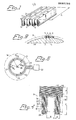
- Figure 1 illustrates in perspective a section.of an originally flat strip of magnetisable material, preferably a material of the kind normally used for manufacturing cores of electrical motor, electrical generators and transformers. It is also possible, however, to use soft-iron sheet or like material, if the efficiency of the machine is ignored.
- the initially planar sheet-metal strip has been bent or folded to form undulations, so as to obtain tooth-like projections 1, 2 which define respective adjacent grooves 3, 4, 5.
- Each groove 3, 4, 5 is arranged to accommodate an electrical conductor or part of a coil hank, while the tooth-like projections 1, 2 form poles in the normal way.
- the folded is clipped to the desired length and then bent around a cylindrical mandral 28, indicated in Figure 2, whereafter the mutually opposing ends of the strip are joined together by welding, glueing or by some other suitable means.
- Figure 2 illustrates in a simplified manner part of a cylindrical rotor 6 produced from a single, bent sheet-metal strip according to Figure 1.
- a sheet-metal strip according to Figure 1 of intended length i.e. a length which is equal to l . D, where D is the diameter of the rotor, has been clipped and bent to form a circular, drum- like core, in which electrical conductors, for example the conductors 7 and 8, are placed in the grooves 3 and 5.
- These conductors may comprise a coil hank or solid rods, the ends of which are short-circuited via a ring.
- the strip illustrated in Figure 1 has been bent around a centre which, in the Figure, lies beneath the strip.
- the strip shown in Figure I is bent around a centre which, in the Figure, lies above the strip. It should be noted that the bent sheet-metal strip from which a stator is to be produced normally has different dimensions to a sheet-metal strip from which a rotor is to be manufactured, due to , for example, the different pole pitch for stator and rotor.
- FIG 3 is a particularly simplified view of a 3-phase motor provided with cores constructed in accordance with the invention, while Figures 4 and 5 illustrate details of the stator 9 and the rotor 10 respectively.
- the stator.9 is stationarily mounted in a manner not specifically shown, and the rotor 10 is fixedly attached by means of clamping means 11, 12 and 13 to the device 14 to be driven around its shaft 38, said shaft being rotatably journalled in bearing means now shown.
- the rotatable drum of washing machines can be mentioned the rotatable drum of washing machines, and in this respect the reference 14 thus identifies the cylindrical end wall of the drum.
- the motor is intended to drive a washing machine, the drum 14 of which can be rotated at different speeds and its direction of movement reversed. If the washing machine is intended to take a load of from 6 to 8kg of washing, it is suitable to take as a suitable point of departure, a 3-phase motor having a maximum torque of about 35Nm at all speeds. This torque corresponds to an approximate power of 3500W at a speed of 1000 r.p.m. If it is desired to produce as thin a motor as possible and the strip-width A ( Figure 1) is chosen as 25mm and the gauge of the strip as 0.5mm (conventional sheet-metal strip for cores) the following principle data for the motor is obtained.
- the stator is provided with 150 grooves each having a width B ( Figure 4) of 3.7mm and a depth C of 10mm, and 150 teeth having a width E of 3.6mm.
- the rotor 10 is provided with 165 grooves and tooth-like projections having a tooth width E of 3mm, a groove width B of 3.7mm and a groove depth C of 8mm.
- the stator is constructed in the manner shown in detail in Figure 4. Pressed into a first, undulated strip 15 of the kind illustrated in Figure 1, is a second undulaled strip 16, the outer dimensions of which are adapted to the inner dimensions of the tooth-like projections in the strip 15 and to the outer dimensions of the groove in strip 1.
- the tooth-like projections are provided with such a width on each tooth on the mutually nestling strips 15, 16, 17 as to obtain close abutment between the inner surface of an outer tooth and the outer surface of a next-following tooth
- the innermost tooth which in the Figure embodiment is formed by the strip 17
- the stator conductors or hank conductors 18 and 19 indicated in Figure 4 can be placed.in position prior to bending the undulating strips 15, 16, 17 into cylinder form of circular cross-section, although said conductors can naturally be placed in position after bending said strips to form said cylinder.
- the width of the strip 20 is suitably the same as the width of the bent or folded strips 15 - 17. If the free, outer end of the strip 20 is not welded or bonded to the underlying strip turn, the whole of the stator 9 can be pressed into a cylindrical holder or like device, which may be incorporated, for example, in a frame structure in the machine in which the motor is to be installed.
- the rotor 10 of which a detail is illustrated in Figure 5, is constructed in the present embodiment in a manner corresponding to the stator in Figure 4, with three bent or folded strips and an inner, planar strip wound through several turns.
- This plana strip which also has the same width as the undulating strips in the rotor and stator , is, in the illustrated case, only wound seven turns, and the distance between the groove bottom and the inner diameter of the rotor is about 5mm.
- a motor having the aforementioned dimensions obtains a linear current density of about 20000A/m at maximum torque and a maximum magnetic flux density in the air gap, B med' of about 0.6 T .
- Figure 5 illustrates a short-circuited rotor 10 having pressed in the grooves thereof, in a manner known per se, aluminium conductors, for example the conductors 23 and 24, the ends of which are conductively connected to each other by means of a short-circuiting ring 25 on both ends of the rotor.
- the short-circuiting rings are pressed onto said ends at the same time as the conductors 23 and 24 are pressed into said grooves.
- control means 22 ( Figure 3) of the kind described in Swiss Patent Application Number 8097/81.
- a core of the kind described can be used for any kind of electric motor or generator whatsoever having a stator andbr rotor provided with pole-forming tooth-like projections, for example a d.c. motor, an asyncrcnous generator and asyncronous motor, in addition to the aforedescribed short-circuited induction motor.
- the junction between two mutually connecting sides for example the sides 26 and 27 ( Figure 4) is suitably formed gently, i.e. so as not to be abrupt.
- the bent or folded strip surfaces pairwise form right angles with each other, although, as will be understood, it is possible in certain cases to bend or fold the strip so that , prior to bending said strip to form a cylinder, the grooves have a frusto-conical cross-sectional shape, which changes-to a rectangular shape when the strip is bent to said circular form.
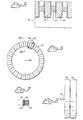
- Figure 6 is a simplified view of this kind of stator, in which one or more undulating strips are bent in a circle around the centre of rotation 39 of the machine.
- Figure 6 illustrates a conductor hank 29 arranged in two mutually adjacent grooves with an intermediate tooth 30, in a strip 31.
- three undulating, folded strips 31, 32 and 33 have been used, and that these strips are arranged in the manner described with reference to Figure 4.
- a planarstrip 34 is wound spirally to form a ring and, as evident from Figure 7, the number of turns in the ring of the illustrated embodiment is such that said ring obtains the same width as the strips 31 - 33 of mutually equal width.
- the ring formed from the strip 34 and manufactured from a suitable magnetisable material is secured to the ring comprising said undulating, folded strips in a manner not shown, for example by means of bolts passing through said undulating strips and said ring the grooves and tooth-like projections of said ring lying in a plain extending at right angles to the axis 37.
- Figure 8 is a simplified view of an axial magnetic flux machine, comprising a disc-like stator 35 according to Figure 6 and a disc-like rotor 36 having an output shaft 37.
Landscapes
- Engineering & Computer Science (AREA)
- Power Engineering (AREA)
- Manufacture Of Motors, Generators (AREA)
- Iron Core Of Rotating Electric Machines (AREA)
- Insulating Of Coils (AREA)
- Manufacturing Cores, Coils, And Magnets (AREA)
Priority Applications (1)
| Application Number | Priority Date | Filing Date | Title |
|---|---|---|---|
| AT82850220T ATE34889T1 (de) | 1982-06-29 | 1982-11-03 | Magnetisierbarer eisenkern zur unterbringung elektrischer leiter in einer elektrischen maschine und ein verfahren zur herstellung solch eines kernes. |
Applications Claiming Priority (2)
| Application Number | Priority Date | Filing Date | Title |
|---|---|---|---|
| CH3970/82A CH648961A5 (fr) | 1982-06-29 | 1982-06-29 | Noyau magnetisable destine a recevoir des conducteurs electriques dans une machine electrique, et procede pour la fabrication de ce noyau. |
| CH3970/82 | 1982-06-29 |
Publications (3)
| Publication Number | Publication Date |
|---|---|
| EP0097756A2 true EP0097756A2 (de) | 1984-01-11 |
| EP0097756A3 EP0097756A3 (en) | 1985-04-03 |
| EP0097756B1 EP0097756B1 (de) | 1988-06-01 |
Family
ID=4267361
Family Applications (1)
| Application Number | Title | Priority Date | Filing Date |
|---|---|---|---|
| EP82850220A Expired EP0097756B1 (de) | 1982-06-29 | 1982-11-03 | Magnetisierbarer Eisenkern zur Unterbringung elektrischer Leiter in einer elektrischen Maschine und ein Verfahren zur Herstellung solch eines Kernes |
Country Status (7)
| Country | Link |
|---|---|
| US (1) | US4546282A (de) |
| EP (1) | EP0097756B1 (de) |
| JP (1) | JPS5911743A (de) |
| AT (1) | ATE34889T1 (de) |
| CH (1) | CH648961A5 (de) |
| DE (1) | DE3278611D1 (de) |
| ES (2) | ES8404560A1 (de) |
Cited By (2)
| Publication number | Priority date | Publication date | Assignee | Title |
|---|---|---|---|---|
| EP0652622A3 (de) * | 1993-11-08 | 1998-08-26 | Mitsubishi Denki Kabushiki Kaisha | Rotierender Motor und sein Herstellungsverfahren, Blechkern und sein Herstellungsverfahren |
| US6121711A (en) * | 1993-11-08 | 2000-09-19 | Mitsubishi Denki Kabushiki Kaisha | Rotary motor and production method thereof, and laminated core and production method thereof |
Families Citing this family (12)
| Publication number | Priority date | Publication date | Assignee | Title |
|---|---|---|---|---|
| US4745675A (en) * | 1983-03-25 | 1988-05-24 | General Motors Corporation | Method of manufacturing laminations for electrical apparatus |
| US4553058A (en) * | 1984-03-30 | 1985-11-12 | Aisin Seiki Kabushiki Kaisha | Low profile direct current motor |
| DE4239106C2 (de) * | 1992-11-20 | 1993-11-25 | Alfred Frohnert | Wartungsfreier Mehrschicht-Generator |
| EP1420498B1 (de) * | 2002-11-15 | 2006-06-14 | Minebea Co., Ltd. | Ständeraufbau für eine elektrische Maschine und Herstellungsverfahren für denselben |
| AU2004242442B2 (en) * | 2003-12-26 | 2010-07-01 | Lg Electronics Inc. | Motor for washing machine |
| KR100600758B1 (ko) * | 2004-09-15 | 2006-07-19 | 엘지전자 주식회사 | 모터의 스테이터 및 그 제조방법 |
| DE102004045992A1 (de) * | 2004-09-22 | 2006-04-06 | Siemens Ag | Elektrische Maschine |
| ES2461294T3 (es) * | 2008-07-30 | 2014-05-19 | Askoll Holding S.R.L. | Procedimiento para la fabricación de un estator para un motor eléctrico y de un motor eléctrico, estator y motor eléctrico |
| MX349325B (es) | 2013-01-04 | 2017-07-24 | Calley David | Estator de cinta de metal y motor que comprende el mismo. |
| JP5839007B2 (ja) * | 2013-09-03 | 2016-01-06 | 株式会社デンソー | 回転電機の固定子鉄心およびその製造方法 |
| DE102019203883A1 (de) * | 2019-03-21 | 2020-09-24 | Robert Bosch Gmbh | Ringförmiger Stator und Verfahren zu seiner Herstellung |
| WO2026018727A1 (ja) * | 2024-07-14 | 2026-01-22 | Ecdl合同会社 | 積層軟磁性薄帯によるラジアルギャップモータ用固定子または回転子 |
Family Cites Families (5)
| Publication number | Priority date | Publication date | Assignee | Title |
|---|---|---|---|---|
| DE534319C (de) * | 1924-12-16 | 1931-09-24 | Eduard Uller | Elektrischer Stromerzeuger |
| US2498702A (en) * | 1944-09-15 | 1950-02-28 | Nahman Gustave | Cylindrical magnetic core |
| US3983435A (en) * | 1974-11-05 | 1976-09-28 | General Electric Company | Stator assembly formed of flat, strip material |
| US3983433A (en) * | 1974-11-05 | 1976-09-28 | General Electric Company | Wire stator core structure and method of making same |
| SU584392A1 (ru) * | 1975-10-28 | 1977-12-15 | Предприятие П/Я Г-4012 | Разъемный статор электрической машины |
-
1982
- 1982-06-29 CH CH3970/82A patent/CH648961A5/fr not_active IP Right Cessation
- 1982-11-03 DE DE8282850220T patent/DE3278611D1/de not_active Expired
- 1982-11-03 EP EP82850220A patent/EP0097756B1/de not_active Expired
- 1982-11-03 AT AT82850220T patent/ATE34889T1/de active
-
1983
- 1983-06-28 ES ES524002A patent/ES8404560A1/es not_active Expired
- 1983-06-28 JP JP58115345A patent/JPS5911743A/ja active Granted
- 1983-06-28 ES ES524003A patent/ES8404561A1/es not_active Expired
-
1984
- 1984-09-27 US US06/655,351 patent/US4546282A/en not_active Expired - Fee Related
Cited By (5)
| Publication number | Priority date | Publication date | Assignee | Title |
|---|---|---|---|---|
| US6362553B1 (en) | 1989-11-08 | 2002-03-26 | Mitsubishi Denki Kabushiki Kaisha | Rotary motor and production method thereof, and laminated core production method thereof |
| EP0652622A3 (de) * | 1993-11-08 | 1998-08-26 | Mitsubishi Denki Kabushiki Kaisha | Rotierender Motor und sein Herstellungsverfahren, Blechkern und sein Herstellungsverfahren |
| US6121711A (en) * | 1993-11-08 | 2000-09-19 | Mitsubishi Denki Kabushiki Kaisha | Rotary motor and production method thereof, and laminated core and production method thereof |
| US6167610B1 (en) | 1993-11-08 | 2001-01-02 | Mitsubishi Denki Kabushiki Kaisha | Method of making a rotary motor |
| US6323571B1 (en) | 1993-11-08 | 2001-11-27 | Mitsubishi Denki Kabushiki Kaisha | Rotary motor and production method thereof, and laminated core and production method thereof |
Also Published As
| Publication number | Publication date |
|---|---|
| ES524003A0 (es) | 1984-05-16 |
| ES524002A0 (es) | 1984-05-16 |
| EP0097756A3 (en) | 1985-04-03 |
| ES8404561A1 (es) | 1984-05-16 |
| ES8404560A1 (es) | 1984-05-16 |
| EP0097756B1 (de) | 1988-06-01 |
| ATE34889T1 (de) | 1988-06-15 |
| US4546282A (en) | 1985-10-08 |
| CH648961A5 (fr) | 1985-04-15 |
| DE3278611D1 (en) | 1988-07-07 |
| JPS5911743A (ja) | 1984-01-21 |
| JPH0213540B2 (de) | 1990-04-04 |
Similar Documents
| Publication | Publication Date | Title |
|---|---|---|
| EP0097756A2 (de) | Magnetisierbarer Eisenkern zur Unterbringung elektrischer Leiter in einer elektrischen Maschine und ein Verfahren zur Herstellung solch eines Kernes | |
| US5294855A (en) | Electromotive device | |
| EP1766757B1 (de) | Statorkern einer dynamoelektrischen maschine mit mini-kappen | |
| US5866965A (en) | Variable reluctance motor having foil wire wound coils | |
| US6555942B1 (en) | Assembly type stator structure having flat wire wound coils | |
| KR100923463B1 (ko) | 발전기기 고정자 및 그것에 예비권선 코일을 설치하는 방법 | |
| US4398112A (en) | Aminated winding for electric machines | |
| EP1073179B1 (de) | Wicklung für einen nutenlosen Stator und Verfahren zu seiner Herstellung | |
| KR101107884B1 (ko) | 차량용 회전 전기기계 | |
| US20040145267A1 (en) | Liners for stators and rotors of electric machines and methods of making | |
| HK1000977B (en) | Method for making an electric motor winding | |
| JP3662994B2 (ja) | 多相多極機 | |
| US20240186840A1 (en) | Ring cylindrical casing and method for producing a ring cylindrical casing of a rotating electromechanical apparatus | |
| US20060038461A1 (en) | Optimized air core armature | |
| JP3480317B2 (ja) | 電気回転機および回転機コイル | |
| JP6968215B2 (ja) | 回転電機 | |
| JP2013085476A (ja) | 回転電機の固定子 | |
| JPS60207435A (ja) | 発電機 | |
| JP2007312564A (ja) | 回転電機の固定子 | |
| US20040143956A1 (en) | Method and apparatus for insertion of stator core liners | |
| JP2010183839A (ja) | 回転電機の固定子 | |
| JP2019122189A (ja) | 絶縁体、固定子、回転電機、および回転電機の製造方法 | |
| JP3015727U (ja) | 自励交流発電機のステータコア | |
| SU1077010A1 (ru) | Магнитопровод торцовой электрической машины | |
| SE439220B (sv) | Av magnetiserbart material bestaende kerna for en elektrisk maskin samt sett att tillverka en sadan kerna |
Legal Events
| Date | Code | Title | Description |
|---|---|---|---|
| PUAI | Public reference made under article 153(3) epc to a published international application that has entered the european phase |
Free format text: ORIGINAL CODE: 0009012 |
|
| AK | Designated contracting states |
Designated state(s): AT BE DE FR GB IT NL SE |
|
| PUAL | Search report despatched |
Free format text: ORIGINAL CODE: 0009013 |
|
| AK | Designated contracting states |
Designated state(s): AT BE DE FR GB IT NL SE |
|
| RHK1 | Main classification (correction) |
Ipc: H02K 1/06 |
|
| 17P | Request for examination filed |
Effective date: 19850215 |
|
| GRAA | (expected) grant |
Free format text: ORIGINAL CODE: 0009210 |
|
| AK | Designated contracting states |
Kind code of ref document: B1 Designated state(s): AT BE DE FR GB IT NL SE |
|
| REF | Corresponds to: |
Ref document number: 34889 Country of ref document: AT Date of ref document: 19880615 Kind code of ref document: T |
|
| REF | Corresponds to: |
Ref document number: 3278611 Country of ref document: DE Date of ref document: 19880707 |
|
| ET | Fr: translation filed | ||
| ITF | It: translation for a ep patent filed | ||
| PLBE | No opposition filed within time limit |
Free format text: ORIGINAL CODE: 0009261 |
|
| STAA | Information on the status of an ep patent application or granted ep patent |
Free format text: STATUS: NO OPPOSITION FILED WITHIN TIME LIMIT |
|
| 26N | No opposition filed | ||
| PGFP | Annual fee paid to national office [announced via postgrant information from national office to epo] |
Ref country code: GB Payment date: 19891031 Year of fee payment: 8 |
|
| PGFP | Annual fee paid to national office [announced via postgrant information from national office to epo] |
Ref country code: FR Payment date: 19891107 Year of fee payment: 8 |
|
| PGFP | Annual fee paid to national office [announced via postgrant information from national office to epo] |
Ref country code: SE Payment date: 19891109 Year of fee payment: 8 |
|
| PGFP | Annual fee paid to national office [announced via postgrant information from national office to epo] |
Ref country code: AT Payment date: 19891114 Year of fee payment: 8 |
|
| PGFP | Annual fee paid to national office [announced via postgrant information from national office to epo] |
Ref country code: BE Payment date: 19891117 Year of fee payment: 8 |
|
| PGFP | Annual fee paid to national office [announced via postgrant information from national office to epo] |
Ref country code: NL Payment date: 19891130 Year of fee payment: 8 |
|
| PGFP | Annual fee paid to national office [announced via postgrant information from national office to epo] |
Ref country code: DE Payment date: 19891229 Year of fee payment: 8 |
|
| PG25 | Lapsed in a contracting state [announced via postgrant information from national office to epo] |
Ref country code: GB Effective date: 19901103 Ref country code: AT Effective date: 19901103 |
|
| PG25 | Lapsed in a contracting state [announced via postgrant information from national office to epo] |
Ref country code: SE Effective date: 19901104 |
|
| PG25 | Lapsed in a contracting state [announced via postgrant information from national office to epo] |
Ref country code: BE Effective date: 19901130 |
|
| BERE | Be: lapsed |
Owner name: S.A. INSTITUT CERAC Effective date: 19901130 |
|
| PG25 | Lapsed in a contracting state [announced via postgrant information from national office to epo] |
Ref country code: NL Effective date: 19910601 |
|
| GBPC | Gb: european patent ceased through non-payment of renewal fee | ||
| NLV4 | Nl: lapsed or anulled due to non-payment of the annual fee | ||
| PG25 | Lapsed in a contracting state [announced via postgrant information from national office to epo] |
Ref country code: FR Effective date: 19910731 |
|
| PG25 | Lapsed in a contracting state [announced via postgrant information from national office to epo] |
Ref country code: DE Effective date: 19910801 |
|
| REG | Reference to a national code |
Ref country code: FR Ref legal event code: ST |
|
| EUG | Se: european patent has lapsed |
Ref document number: 82850220.3 Effective date: 19910705 |