EP0097845A1 - Procédé et dispositif pour déterminer la distorsion de l'atténuation et du temps de transit de groupe d'un objet de mesure, particulièrement d'un trajet de transmission de données - Google Patents
Procédé et dispositif pour déterminer la distorsion de l'atténuation et du temps de transit de groupe d'un objet de mesure, particulièrement d'un trajet de transmission de données Download PDFInfo
- Publication number
- EP0097845A1 EP0097845A1 EP83105551A EP83105551A EP0097845A1 EP 0097845 A1 EP0097845 A1 EP 0097845A1 EP 83105551 A EP83105551 A EP 83105551A EP 83105551 A EP83105551 A EP 83105551A EP 0097845 A1 EP0097845 A1 EP 0097845A1
- Authority
- EP
- European Patent Office
- Prior art keywords
- phase
- pulse
- test
- test pulse
- frequency offset
- Prior art date
- Legal status (The legal status is an assumption and is not a legal conclusion. Google has not performed a legal analysis and makes no representation as to the accuracy of the status listed.)
- Granted
Links
- 238000000034 method Methods 0.000 title claims abstract description 19
- 230000005540 biological transmission Effects 0.000 title claims abstract description 6
- 238000012360 testing method Methods 0.000 claims abstract description 52
- 230000010355 oscillation Effects 0.000 claims abstract description 25
- 230000002452 interceptive effect Effects 0.000 claims abstract 2
- 238000005259 measurement Methods 0.000 claims description 38
- 238000012937 correction Methods 0.000 claims description 3
- 238000013016 damping Methods 0.000 claims description 3
- 238000006073 displacement reaction Methods 0.000 abstract 4
- 238000001228 spectrum Methods 0.000 description 7
- 238000005070 sampling Methods 0.000 description 5
- 230000009466 transformation Effects 0.000 description 2
- 238000004364 calculation method Methods 0.000 description 1
- 238000004590 computer program Methods 0.000 description 1
- 230000001419 dependent effect Effects 0.000 description 1
- 238000010586 diagram Methods 0.000 description 1
- 238000011156 evaluation Methods 0.000 description 1
- 238000012432 intermediate storage Methods 0.000 description 1
- 238000000691 measurement method Methods 0.000 description 1
- 238000003860 storage Methods 0.000 description 1
Images
Classifications
-
- G—PHYSICS
- G01—MEASURING; TESTING
- G01R—MEASURING ELECTRIC VARIABLES; MEASURING MAGNETIC VARIABLES
- G01R23/00—Arrangements for measuring frequencies; Arrangements for analysing frequency spectra
- G01R23/16—Spectrum analysis; Fourier analysis
- G01R23/20—Measurement of non-linear distortion
-
- G—PHYSICS
- G01—MEASURING; TESTING
- G01R—MEASURING ELECTRIC VARIABLES; MEASURING MAGNETIC VARIABLES
- G01R27/00—Arrangements for measuring resistance, reactance, impedance, or electric characteristics derived therefrom
- G01R27/28—Measuring attenuation, gain, phase shift or derived characteristics of electric four pole networks, i.e. two-port networks; Measuring transient response
Definitions
- the invention relates to a method and an arrangement for determining the attenuation distortion and the group delay distortion of a test object, in particular a data transmission link, in which a test pulse is fed to the test object and the deformation of the test pulse caused by the test object is evaluated at the output of the test object (pulse response).
- the test pulse consists of vibrations of different frequencies that are predetermined with respect to their amplitude and phase, with the help of Fourier analysis the pulse response is broken down and the individual frequency components are determined with regard to their amplitudes and their phase relationship to one another and by comparing the pulse response with that originally sent test pulse ämpfungs- the D and group delay distortion is determined.
- a data line is acted upon as a test object with a test pulse which consists of there is a number of cosine vibrations that are evenly distributed, for example, over a frequency range from 0.2 to 3.6 kHz.
- the test pulse with its deformations caused by the measurement object is analyzed with the aid of the fast Fourier transformation and the transmission behavior of the data line is determined on the basis of the changes in the magnitude and phase of the individual cosine oscillations.
- the transmission behavior of a sol Chen data line can also be influenced by a frequency offset of the vibrations at the output of the data line compared to the vibrations at the input of the data line, due to frequency converters in the course of the data line.
- a frequency offset of the vibrations at the output of the data line compared to the vibrations at the input of the data line, due to frequency converters in the course of the data line.
- this is not very disturbing as long as the frequency offset is below a predetermined tolerance limit; for applications, however, there is a risk that a predetermined tolerance limit will be exceeded.
- the invention has for its object to provide a method and an arrangement for determining the attenuation and group delay distortion of a test object, in which the influence of a frequency offset caused by the test object is largely corrected.
- the object is achieved in a method of the type mentioned at the outset in that in a first measurement phase the frequency difference (frequency offset) between the predetermined vibrations of the test pulse and corresponding vibrations of the pulse response is determined and in a second measurement phase the amplitude and the phase of the vibrations influenced by the measurement object, inter alia with a frequency offset, and in a third measurement phase the due to the superimposition of secondary wave components caused by the frequency offset of each vibration neighboring vibrations can be compensated.
- the frequency offset can be determined in the method according to the invention in a manner known per se. B. by measuring the frequency difference of at least one of the vibrations at the output of the test object, from the corresponding known, predetermined vibration at the input of the test object or by a known two-tone measurement method.
- This frequency difference represents the frequency offset caused by the measurement object and is advantageously used during the third measurement phase to correct the influence on the amount and the phase of the individual vibrations caused by this frequency offset.
- the disruptive influence of the frequency offset is primarily caused by the secondary waves of each harmonic oscillation, which arise from a jump point at the sampling period limit caused by the frequency shift in the Fourier analysis.
- the influence of the frequency offset can be determined in a particularly advantageous manner if, in the second measurement phase, the disturbing spurious wave components of each harmonic oscillation caused by the frequency-related harmonic oscillation due to the frequency offset are determined from the magnitude of the frequency offset and the magnitude and phase of the oscillation and in the third phase of measurement the influence of each secondary wave component by in-phase sub traction of the disturbing auxiliary wave component is eliminated by the respective harmonic oscillation, the auxiliary wave components caused by harmonic vibrations which are distant in frequency being determined and eliminated in a further embodiment of the method.
- an arrangement has a measuring transmitter for generating the test pulse and a measuring module for evaluating the test pulse with the aid of the fast Fourier analysis at the output of the measuring object and a display module for displaying the compensated output signal of the measuring object.
- a compensation circuit is advantageously present, in which a signal corresponding to the measured frequency offset is present at one input, the test pulse evaluated by the measuring module is present at another input and with which the correction of the superposition of the components of the auxiliary waves caused by the frequency offset is applied every harmonic is performed.
- the output signal of the measurement module for carrying out the Fourier analysis and the frequency offset by the measurement object for carrying out the method according to the invention are evaluated.
- the compensation circuit can contain, for example, a microcomputer that is based on an input computer program determines the influence of the secondary wave components caused by the frequency offset at the output of the test object.
- the influence caused by the frequency offset can thus be compensated for by calculation.
- the values displayed on the display module and determined from the output signal of the measurement object are thus corrected for the incorrect influence of the frequency offset, so that an extremely precise measurement of the attenuation and group delay distortion of the measurement object is possible.
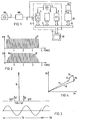
- the measuring module 4 contains an analog-digital converter 5, which, controlled by a clock generator 6, provides discrete samples of the test pulse at the output of the measurement object MO to a bus line 7 of the measuring module 4.
- the sampled values are stored in a buffer 8 and then evaluated in an analysis module 9 using the fast Fourier transform (FET).
- FET fast Fourier transform
- the analysis module 9 is driven here by the same clock of the clock generator 6 as the analog-digital converter 5 and is via the bus line 7 with a comm Connection module KB connected, which compensates for the influence of the error caused by a frequency offset in the area of the measurement object on the output signal of the analysis module 9, the data resulting from the fast Fourier transformation being transmitted via the bus line 10.
- a further quantity is supplied to the compensation module KB via a line 11, which corresponds to the frequency offset 6F and was determined in the module Fv at the output of the measurement object MO or in some other way.
- the output signal of the analysis module 9, which contains the information, inter alia, about the attenuation and group delay distortion after the correction, is fed via the bus line 7 and an output line 12 to a display module AB.
- the lines 15 identify the individually predetermined vibrations at the input of the test object, which are all harmonics of the fundamental 100 Hz in this embodiment and extend over the range from 200 Hz to 3.6 kHz. All predetermined vibrations 15 have the same standard level at the input of the measurement object MO.
- the lines 16 of the line spectrum P2, which appear at the output 2 of the measurement object MO, have changes particularly in the lower and in the upper frequency range, which are caused, for example, by frequency-dependent damping of the measurement object MO.
- FIG. 3 shows a single one of the predetermined vibrations, which in the upper part - in frequency area shown - one of the lines 16, z. B. at 1 kHz + & F corresponds. Due to the frequency offset of the measurement object, an integer multiple of the period of the oscillation does not fall into one sampling period, so that in the Fourier analysis secondary lines Al, A2 etc. (not shown here) or Al ', A2' etc. (not shown here) arise. In the lower part of FIG.
- this harmonic oscillation corresponding to the line 16 at 1 kHz is shown in the time domain, inter alia, during the predetermined sampling period TA, with the frequency offset ⁇ F resulting in a jump at the end of the sampling period TA, which is used to form the aforementioned Branch lines leads.
- each line in the frequency range results as shown in FIG. 2 below as a superposition of all components, i.e. H. the harmonic oscillation and the secondary wave components (secondary lines) of the other harmonics at the respective frequency.
- the previously determined frequency shift (frequency offset 6F) is used in the further measurement phases of the method according to the invention in the compensation module KB according to FIG. 1 to determine the amounts, taking into account the phases of the secondary wave components of each individual vibration as they overlap within the individual lines of the line spectrum, and then to correct. It is thus possible to subtract the superposition of secondary shaft components caused by the frequency offset in each individual line.
- the representation of a line 16 in the complex plane according to FIG. 4 shows that if the phase position of the individual auxiliary wave components is also taken into account, a compensation of the phase distortion caused by the frequency offset can also be carried out, so that after compensation of all influences according to amount and phase a Line 17 would result.
- the superimpositions An, Bn, Cn are the secondary waves of the other harmonics of the test pulse in the harmonic oscillation shown here. Since the distortion of the amount and the phase of each individual oscillation of the test pulse caused by a frequency offset can thus be determined and compensated, it is possible to determine the attenuation and group delay distortion of the test object while largely eliminating the influence of a frequency offset.
Landscapes
- Physics & Mathematics (AREA)
- General Physics & Mathematics (AREA)
- Nonlinear Science (AREA)
- Mathematical Physics (AREA)
- Measurement Of Mechanical Vibrations Or Ultrasonic Waves (AREA)
- Measurement Of Resistance Or Impedance (AREA)
Applications Claiming Priority (2)
| Application Number | Priority Date | Filing Date | Title |
|---|---|---|---|
| DE3224080 | 1982-06-28 | ||
| DE19823224080 DE3224080A1 (de) | 1982-06-28 | 1982-06-28 | Verfahren zur ermittlung der daempfungsverzerrung und der gruppenlaufzeitverzerrung eines messobjekts, insbesondere einer datenuebertragungsstrecke |
Publications (2)
| Publication Number | Publication Date |
|---|---|
| EP0097845A1 true EP0097845A1 (fr) | 1984-01-11 |
| EP0097845B1 EP0097845B1 (fr) | 1987-01-07 |
Family
ID=6167035
Family Applications (1)
| Application Number | Title | Priority Date | Filing Date |
|---|---|---|---|
| EP83105551A Expired EP0097845B1 (fr) | 1982-06-28 | 1983-06-06 | Procédé et dispositif pour déterminer la distorsion de l'atténuation et du temps de transit de groupe d'un objet de mesure, particulièrement d'un trajet de transmission de données |
Country Status (2)
| Country | Link |
|---|---|
| EP (1) | EP0097845B1 (fr) |
| DE (2) | DE3224080A1 (fr) |
Cited By (1)
| Publication number | Priority date | Publication date | Assignee | Title |
|---|---|---|---|---|
| EP0499346A1 (fr) * | 1987-04-28 | 1992-08-19 | Racal Communications Equipment Limited | Procédé pour tester un amplificateur pour établir ses caractéristiques de distorsion dues aux produits d'intermodulation |
Families Citing this family (1)
| Publication number | Priority date | Publication date | Assignee | Title |
|---|---|---|---|---|
| DE3445915C2 (de) * | 1984-01-09 | 1994-09-29 | Hewlett Packard Co | Hochfrequenz-Netzwerkanalysator |
Citations (3)
| Publication number | Priority date | Publication date | Assignee | Title |
|---|---|---|---|---|
| DE2849119A1 (de) * | 1978-11-13 | 1980-05-14 | Siemens Ag | Verfahren und schaltungsanordnung zur daempfungsmessung, insbesondere zur ermittlung der daempfungs- und/oder gruppenlaufzeitverzerrung eines messobjektes |
| US4264959A (en) * | 1977-06-02 | 1981-04-28 | Siemens Aktiengesellschaft | Testing procedure and circuit for the determination of frequency distortions and group delay time distortion of a test object |
| DE3048831A1 (de) * | 1979-12-28 | 1981-09-24 | Western Electric Co., Inc., 10038 New York, N.Y. | "mehrton-verfahren und -vorrichtung zum messen des frequenzgangs und der gruppenlaufzeitverzerrung" |
-
1982
- 1982-06-28 DE DE19823224080 patent/DE3224080A1/de not_active Withdrawn
-
1983
- 1983-06-06 EP EP83105551A patent/EP0097845B1/fr not_active Expired
- 1983-06-06 DE DE8383105551T patent/DE3369001D1/de not_active Expired
Patent Citations (3)
| Publication number | Priority date | Publication date | Assignee | Title |
|---|---|---|---|---|
| US4264959A (en) * | 1977-06-02 | 1981-04-28 | Siemens Aktiengesellschaft | Testing procedure and circuit for the determination of frequency distortions and group delay time distortion of a test object |
| DE2849119A1 (de) * | 1978-11-13 | 1980-05-14 | Siemens Ag | Verfahren und schaltungsanordnung zur daempfungsmessung, insbesondere zur ermittlung der daempfungs- und/oder gruppenlaufzeitverzerrung eines messobjektes |
| DE3048831A1 (de) * | 1979-12-28 | 1981-09-24 | Western Electric Co., Inc., 10038 New York, N.Y. | "mehrton-verfahren und -vorrichtung zum messen des frequenzgangs und der gruppenlaufzeitverzerrung" |
Cited By (1)
| Publication number | Priority date | Publication date | Assignee | Title |
|---|---|---|---|---|
| EP0499346A1 (fr) * | 1987-04-28 | 1992-08-19 | Racal Communications Equipment Limited | Procédé pour tester un amplificateur pour établir ses caractéristiques de distorsion dues aux produits d'intermodulation |
Also Published As
| Publication number | Publication date |
|---|---|
| DE3369001D1 (en) | 1987-02-12 |
| DE3224080A1 (de) | 1983-12-29 |
| EP0097845B1 (fr) | 1987-01-07 |
Similar Documents
| Publication | Publication Date | Title |
|---|---|---|
| DE69923815T2 (de) | FM-CW Radarvorrichtung | |
| DE2849119C2 (fr) | ||
| DE3878045T2 (de) | Verfahren zur auswertung der signalfrequenz und phase und anordnung zur durchfuehrung dieses verfahrens. | |
| DE2219085C3 (de) | Frequenzanalysator | |
| EP0440931B1 (fr) | Appareil de contrÔle à courants de Foucault | |
| DE2724991B2 (de) | Meßverfahren und Schaltungsanordnung zur Ermittlung der Dämpfungsverzerrung und der Gruppenlaufzeitverzerrung eines Meßobjekts | |
| EP0677172A1 (fr) | Procede informatise faisant appel a un radar, pour mesurer les distances et les vitesses relatives entre un vehicule et des obstacles se trouvant en face de lui | |
| DE2726270C2 (fr) | ||
| DE68915255T2 (de) | Frequenzmessung. | |
| DE3024346C2 (fr) | ||
| DE19833921A1 (de) | Schnelle Fourier-Transformationsvorrichtung | |
| EP0203934B1 (fr) | Montage de circuit pour la mesure du couple | |
| DE69307009T2 (de) | Anordnung zur Quadraturfehlerkorrektion eines Synchrondemodulators | |
| DE2223940A1 (de) | Verfahren und Anordnung zur Filterung elektrischer Signale | |
| EP0097845B1 (fr) | Procédé et dispositif pour déterminer la distorsion de l'atténuation et du temps de transit de groupe d'un objet de mesure, particulièrement d'un trajet de transmission de données | |
| DE3538326A1 (de) | Anordnung zur berechnung des phasenwinkels eines summenvektors | |
| DE19961817A1 (de) | Frequenzabweichung detektierendes Gerät und Frequenzabweichungs-Detektionsverfahren | |
| DE68904743T2 (de) | Verfahren zum nachweis elektrischer groessen. | |
| EP0349078B1 (fr) | Circuit de production de signaux haute fréquence pour l'examen par spin nucléaire | |
| DE3709532A1 (de) | Verfahren zur pruefung von anordnungen | |
| DE3245505A1 (de) | Verfahren zur schadensfrueherkennung | |
| EP0357141B1 (fr) | Générateur de haute fréquence pour un appareil d'examen à spin nucléaire | |
| EP1126730B1 (fr) | Procédé de detection de changement de phase d'un signal ou d'une tonalité | |
| EP0673129A2 (fr) | Procédé et dispositif pour déterminer le rapport porteuse sur interférence pour l'interférence d'un même canal ou d'un canal adjacent dans un réseau numérique radio mobile | |
| DE3874174T2 (de) | Digitaler lokalisator. |
Legal Events
| Date | Code | Title | Description |
|---|---|---|---|
| PUAI | Public reference made under article 153(3) epc to a published international application that has entered the european phase |
Free format text: ORIGINAL CODE: 0009012 |
|
| AK | Designated contracting states |
Designated state(s): BE DE FR GB IT |
|
| 17P | Request for examination filed |
Effective date: 19840705 |
|
| GRAA | (expected) grant |
Free format text: ORIGINAL CODE: 0009210 |
|
| AK | Designated contracting states |
Kind code of ref document: B1 Designated state(s): BE DE FR GB IT |
|
| REF | Corresponds to: |
Ref document number: 3369001 Country of ref document: DE Date of ref document: 19870212 |
|
| ET | Fr: translation filed | ||
| ITF | It: translation for a ep patent filed | ||
| PLBE | No opposition filed within time limit |
Free format text: ORIGINAL CODE: 0009261 |
|
| STAA | Information on the status of an ep patent application or granted ep patent |
Free format text: STATUS: NO OPPOSITION FILED WITHIN TIME LIMIT |
|
| 26N | No opposition filed | ||
| PGFP | Annual fee paid to national office [announced via postgrant information from national office to epo] |
Ref country code: GB Payment date: 19900521 Year of fee payment: 8 |
|
| PGFP | Annual fee paid to national office [announced via postgrant information from national office to epo] |
Ref country code: BE Payment date: 19900620 Year of fee payment: 8 |
|
| PGFP | Annual fee paid to national office [announced via postgrant information from national office to epo] |
Ref country code: FR Payment date: 19900628 Year of fee payment: 8 |
|
| ITTA | It: last paid annual fee | ||
| PGFP | Annual fee paid to national office [announced via postgrant information from national office to epo] |
Ref country code: DE Payment date: 19900827 Year of fee payment: 8 |
|
| PG25 | Lapsed in a contracting state [announced via postgrant information from national office to epo] |
Ref country code: GB Effective date: 19910606 |
|
| PG25 | Lapsed in a contracting state [announced via postgrant information from national office to epo] |
Ref country code: BE Effective date: 19910630 |
|
| BERE | Be: lapsed |
Owner name: SIEMENS A.G. BERLIN UND MUNCHEN Effective date: 19910630 |
|
| GBPC | Gb: european patent ceased through non-payment of renewal fee | ||
| PG25 | Lapsed in a contracting state [announced via postgrant information from national office to epo] |
Ref country code: FR Effective date: 19920228 |
|
| PG25 | Lapsed in a contracting state [announced via postgrant information from national office to epo] |
Ref country code: DE Effective date: 19920401 |