EP0097860A2 - Réacteur à gaz d'acetylène - Google Patents
Réacteur à gaz d'acetylène Download PDFInfo
- Publication number
- EP0097860A2 EP0097860A2 EP83105750A EP83105750A EP0097860A2 EP 0097860 A2 EP0097860 A2 EP 0097860A2 EP 83105750 A EP83105750 A EP 83105750A EP 83105750 A EP83105750 A EP 83105750A EP 0097860 A2 EP0097860 A2 EP 0097860A2
- Authority
- EP
- European Patent Office
- Prior art keywords
- container
- acetylene gas
- water
- reactor according
- gas reactor
- Prior art date
- Legal status (The legal status is an assumption and is not a legal conclusion. Google has not performed a legal analysis and makes no representation as to the accuracy of the status listed.)
- Granted
Links
Images

Classifications
-
- C—CHEMISTRY; METALLURGY
- C10—PETROLEUM, GAS OR COKE INDUSTRIES; TECHNICAL GASES CONTAINING CARBON MONOXIDE; FUELS; LUBRICANTS; PEAT
- C10H—PRODUCTION OF ACETYLENE BY WET METHODS
- C10H21/00—Details of acetylene generators; Accessory equipment for, or features of, the wet production of acetylene
Definitions
- the invention relates to an acetylene gas reactor which is also suitable for mobile use and preferably works with low pressure, in particular for feeding a motor vehicle engine, consisting of a calcium carbide storage container, a reaction chamber arranged below the storage container and used for acetylene development, and one connected to the bottom of the storage container , in the reaction chamber protruding screen basket, on which a spray nozzle arrangement for supplying the water required for the reaction is arranged, and an outlet connection connected to the bottom of the reaction chamber for the calcium hydroxide sludge or lime dust produced.
- a motor vehicle engine consisting of a calcium carbide storage container, a reaction chamber arranged below the storage container and used for acetylene development, and one connected to the bottom of the storage container , in the reaction chamber protruding screen basket, on which a spray nozzle arrangement for supplying the water required for the reaction is arranged, and an outlet connection connected to the bottom of the reaction chamber for the calcium hydroxide sludge or lime dust produced.
- the present invention aims to further develop and improve such a reactor, which has already been tried and tested in internal practice, with regard to more practical supply and disposal in connection with cooling and cleaning of the acetylene gas generated at relatively high temperatures.
- a separate gas collection and water supply container fed with the excess water of the reaction chamber is arranged separately from the reaction chamber, that the lower part of this container containing the water supply is connected via a line to the spray nozzle arrangement that from the upper area of the reaction chamber receiving the acetylene, a gas line leads to a bottom opening of the separate container and that the acetylene gas outlet connection leading to the consumers is provided in the upper area of the separate container.
- the actual reactor can now be made much smaller, since gas and water can be stored in a separate container.
- a larger supply of calcium carbide can be stored in a reactor of certain dimensions.
- the calcium carbide storage container of the reactor could, for example, have a capacity of 20 kg of carbide, which corresponds to a mileage of 300 to 400 km in a middle-class motor vehicle.
- Another feature of the invention relates to the collection of the calcium hydroxide sludge or lime dust that is now, according to the development of this invention, conducted via a pipeline - optionally with the addition of a pump - into a collection container to be set up separately. If, according to the proposal of the invention: the same containers with the same connecting dimensions are provided for the calcium carbide refill and for collecting the calcium carbide sludge, it is possible to use a carbide container which has become empty after the carbide feed to receive the carbide sludge.
- a filled sludge container could therefore always be dispensed at a "tank" point and the newly received carbide container could be connected as the next sludge container after it had been emptied into the storage container.
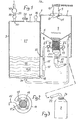
- the reactor according to the invention consists of an essentially cylindrical housing 1, a separate gas collecting and water storage container 2 and a removable collecting container 3 (FIG. 3) for the calcium hydroxide sludge or lime dust that occurs.
- the housing 1 encloses the calcium carbide storage container 4, which is separated from the actual reaction chamber 6 by a funnel-shaped base 5. is.
- the upper end face 7 of the housing 1 has a filling opening 8 in the middle on, which is connected to a filler neck 9, which can be closed with a screw cap 10.
- a closure flap 11 which is resiliently held in the closed position, can be provided in front of the filling opening 8.
- the funnel-shaped bottom 5 of the storage container 4 is provided with a cylindrical strainer basket 12 which extends substantially perpendicularly underneath and into which the calcium carbide can enter from the storage container 4 under the influence of gravity.
- This basket is made of perforated sheet metal or wire mesh.
- the mesh size of the mesh is relatively small on the side walls of the screen basket 12, since the carbide granules pulverize under the influence of the heat of reaction.
- the bottom surface 12a of the sieve is somewhat coarser-meshed so that there is no sticking and incrustation of the powdered calcium carbide granules and the removal of the calcium hydroxide sludge or lime dust is not hindered.
- the strainer basket 12 is surrounded by an annular spray nozzle arrangement 13 with which the water required for the reaction can be sprayed against the walls of the strainer basket 12 and against the calcium carbide contained in the strainer basket.
- the spray nozzle arrangement consists of an annular tube 14, which surrounds the screen basket 12 concentrically. Instead of a self-contained one Ring tube 14 can also serve, as shown in FIG. 2, an annular tube which extends almost over the entire circumference and which is closed at the free end.
- the ring tube 14 is supplied via a line 15 which crosses the wall of the housing 1 and is connected to the lower part of the separate container 2, in which the water required for the reaction is kept in stock.
- the water is conveyed from the separate container 2 to the spray nozzle arrangement 13 preferably via a pump 17 which is switched on in the line 15 and which sucks off the water at the bottom connection 18 of the container 2.
- the ring tube 14 On the inner circumference of the ring tube 14 there are several spray nozzles 19 distributed over the circumference, via which the water required on the ring tube can be fed in the direction of the strainer basket 12. These spray nozzles 19 are directed so that they can irradiate a large part of the walls of the screen basket 12 and the calcium carbide contained therein. However, at least some of the nozzles 19 are preferably directed so that they support the passage of the calcium carbide particles or the calcium carbide powder in the direction of the collecting container 3. When using a pump 17, it can preferably be driven electrically from the on-board battery.
- the pump 17 can also be controlled by a sensor 38 which detects the gas pressure in the upper part 27 of the separate section holder 2 is detected in order to switch on the pump 17 only when a preset minimum pressure of, for example, 100 mb is not reached.
- a funnel 21 arranged below the strainer basket 12 collects the calcium hydroxide sludge falling out of the strainer basket and directs it into a line 22 crossing the bottom of the housing 1, from which the calcium hydroxide sludge under the influence of gravity, supported by that prevailing in the reaction chamber 6 Pressure can reach the reservoir 3.
- a further feed pump 23 electrically driven from the on-board battery can also be provided in line 22.
- the collecting container 3 is not firmly connected to the housing 1.
- a screw cap 24 is also provided here, just as on the carbide filler neck 9, via which the collecting container 3 can be connected and easily removed if necessary. Understandably, the carbide filler neck and also the connecting line to the collecting container 3 are provided with appropriate seals so that the generated acetylene gas cannot escape and the surrounding environment can not smell,
- the screw caps 10 and 24 are preferably of identical design, so that one empties onto the carbide filler neck 9 bare carbide storage container can be used as a collecting container after it has been emptied into the storage container 4. To fill the storage container 4, there is no need to empty the collecting container 3, which can be dispensed with its filling in order to be replaced by an emptied darbide storage container.
- the acetylene gas generated in the reactor chamber when spraying the screen basket contents is extremely hot, so that condensation can occur. So that condensation water is never passed on to the acetylene gas consumers, in the reactor according to the invention the gas is removed from the reaction chamber in the vicinity thereof via a gas line 25 which opens at the end and crosses the wall of the housing 1 and via the bottom opening 26 in the lower one Part 16 of the separate container 2 occurs.
- a gas line 25 which opens at the end and crosses the wall of the housing 1 and via the bottom opening 26 in the lower one Part 16 of the separate container 2 occurs.
- This connector 20 is connected to a pressure reducing valve 28 with which the use pressure of the gas can be adjusted.
- a pipeline 29 leads from the pressure reducing valve 28 to a pulse 30
- a water filler neck 32 is provided in the upper end wall 31 of the container 2, which of course is gas-tight must be closable. A further water filling takes place via a connecting bore 33 between the reaction chamber 6 and the container 2. The excess water is continuously removed from the reaction chamber 6 to the container 2 via this opening 33. out, in which the water level is understandably kept below the level of the opening 33.
- the gas reactor according to the invention works as follows:
- the emptied carbide container is connected to the screw plug 24 in order to then serve as a collecting container for the calcium hydroxide sludge.
- the container 2 is filled with water via the water filler neck 32 to a little below the opening 33.
- the calcium carbide fills the strainer basket 12 due to the force of gravity, which is still favored by normal vehicle vibrations during driving.
- the carbide particles disintegrate and, if they are smaller than the mesh opening of the sieve basket bottom (12a), can fall out downwards. This falling out is favored by the water flow.
- the calcium hydroxide sludge arrives in the collecting container 3. According to the removal of the calcium hydroxide sludge, further carbide can then enter the sieve basket 12 from the storage container 4 for the subsequent reaction.
- the pump 23 switched on in the line 22 is designed such that it only discharges the sludge compressed under the action of pressure from the funnel 21 and at the same time forms a barrier against undesired escape of the acetylene gas from the reaction chamber 6.
- the reactor according to the invention now consists of several chambers, on the one hand there is a larger filling volume for the storage container 4 and on the other hand a lower design which facilitates the installation of the reactor in motor vehicles. It is also of particular advantage that the reactor can be charged with water without opening the actual reaction chamber 6 to the outside. This prevents odor nuisance. It is also particularly advantageous in the reactor according to the invention that the collecting container 3 is arranged separately from the reactor housing 1 and can therefore be separated very easily from the reactor. Of particular importance in the reactor according to the invention, however, is that the very hot acetylene gas which arises in the reaction chamber 6 can be cooled well in the separate container 2, so that undesired condensate formation in the gas lines to the consumer and in the consumer themselves cannot occur.
- the acetylene gas reactor essentially consists of three containers 101, 102 and 140.
- the actual reactor vessel 101 essentially coincides with vessel 1 of FIGS. 1 to 3.
- the difference is that is' d of the carbide reservoir 104 ate downward through a sloping ground limited to a flat configuration screen basket 112 connects to the which is directed towards the interior of the container 101 and extends across the width of the vessel 101 to approximately the center.
- a flat nozzle arrangement 113 which is fed via a line 115, a water pump 117 and a line 118 from the water chamber 116 of the combined gas and water container 102, extends over this screen basket 113 in the same length and width dimensions.
- the acetylene gas formed in the gas space 106 of the container 101 is introduced via a line 115, a pump 117 and a line 118 into the water-filled space 116 of the container 102, so that the gas in the water can be cooled there and then into the gas space 127 rise where it can reach the acetylene gas consumer via the pressure reducing valve 128 and the mixing valve 130.
- a sensor 138 controlling the water supply to the reactor is provided on the gas storage space 127.
- a pressure relief valve 149 prevents the creation of an excess pressure in the gas space 127.
- the container 140 which can be sealed gas-tight with a lid 141, is supported on supports 142 by an upwardly open filter basket, the walls and bottom of which are water-permeable, but retain the solid parts of the carbide sludge.
- the water collecting at the bottom of the container 140 is conveyed into the water compartment 116 of the container 102 via a pump 145 and a line 146.
- the filter basket 103 After the filter insert 103 is filled with the solids of the hydroxide sludge, after opening the cover 141, the filter basket 103 to be filled on its open upper side via the line 144 can be removed from the container 140 on the handle 143 in order to then insert a new filter basket 103.
- the check valves 147 and 148 used in lines 146 and 125 serve to ensure the safety of the reactor system and are only permeable in the direction of the water storage space 116 and block in the opposite direction.
Landscapes
- Chemical & Material Sciences (AREA)
- Oil, Petroleum & Natural Gas (AREA)
- Organic Chemistry (AREA)
- Treatment Of Sludge (AREA)
- Low-Molecular Organic Synthesis Reactions Using Catalysts (AREA)
- Physical Or Chemical Processes And Apparatus (AREA)
- Feeding, Discharge, Calcimining, Fusing, And Gas-Generation Devices (AREA)
Priority Applications (1)
| Application Number | Priority Date | Filing Date | Title |
|---|---|---|---|
| AT83105750T ATE18677T1 (de) | 1982-06-26 | 1983-06-11 | Acetylengas-reaktor. |
Applications Claiming Priority (2)
| Application Number | Priority Date | Filing Date | Title |
|---|---|---|---|
| DE19823223923 DE3223923A1 (de) | 1982-06-26 | 1982-06-26 | Acetylengas-reaktor |
| DE3223923 | 1982-06-26 |
Publications (3)
| Publication Number | Publication Date |
|---|---|
| EP0097860A2 true EP0097860A2 (fr) | 1984-01-11 |
| EP0097860A3 EP0097860A3 (en) | 1984-11-28 |
| EP0097860B1 EP0097860B1 (fr) | 1986-03-19 |
Family
ID=6166937
Family Applications (1)
| Application Number | Title | Priority Date | Filing Date |
|---|---|---|---|
| EP83105750A Expired EP0097860B1 (fr) | 1982-06-26 | 1983-06-11 | Réacteur à gaz d'acetylène |
Country Status (3)
| Country | Link |
|---|---|
| EP (1) | EP0097860B1 (fr) |
| AT (1) | ATE18677T1 (fr) |
| DE (2) | DE3223923A1 (fr) |
Families Citing this family (2)
| Publication number | Priority date | Publication date | Assignee | Title |
|---|---|---|---|---|
| RU2176959C2 (ru) * | 1999-11-01 | 2001-12-20 | Григорчук Владимир Степанович | Автомобиль с гидрогазодинамическим двигателем |
| CN105219435A (zh) * | 2015-11-10 | 2016-01-06 | 天津大沽化工股份有限公司 | 一种从渣浆中回收乙炔的方法 |
Family Cites Families (6)
| Publication number | Priority date | Publication date | Assignee | Title |
|---|---|---|---|---|
| DE186060C (fr) * | ||||
| DE677195C (de) * | 1937-01-28 | 1939-06-21 | Peter Keusen | Acetylenentwickler |
| FR988844A (fr) * | 1944-01-19 | 1951-08-31 | Volcan Sa | Générateur d'acétylène à chaux sèche |
| US4054423A (en) * | 1975-07-21 | 1977-10-18 | Blenman Orman L | Variable pressure fuel generator and method |
| DE3005659A1 (de) * | 1980-02-15 | 1981-08-20 | Wolfgang 2210 Itzehoe Priesemuth | Verfahren zur speisung eines brenners oder gasmotors mit aus carbid freigesetztem acetylen und vorrichtung zur durchfuehrung des verfahrens |
| DE3131670C2 (de) * | 1981-08-11 | 1984-08-23 | Wolfgang 2210 Itzehoe Priesemuth | Acetylengas-Reaktor |
-
1982
- 1982-06-26 DE DE19823223923 patent/DE3223923A1/de not_active Withdrawn
-
1983
- 1983-06-11 EP EP83105750A patent/EP0097860B1/fr not_active Expired
- 1983-06-11 DE DE8383105750T patent/DE3362594D1/de not_active Expired
- 1983-06-11 AT AT83105750T patent/ATE18677T1/de active
Also Published As
| Publication number | Publication date |
|---|---|
| EP0097860A3 (en) | 1984-11-28 |
| EP0097860B1 (fr) | 1986-03-19 |
| DE3362594D1 (en) | 1986-04-24 |
| DE3223923A1 (de) | 1983-12-29 |
| ATE18677T1 (de) | 1986-04-15 |
Similar Documents
| Publication | Publication Date | Title |
|---|---|---|
| EP0071671B1 (fr) | Réacteur de gaz d'acétylène | |
| DE4411078A1 (de) | Filter zum Abscheiden von Schadstoffen aus Rauchgasen | |
| DE2536644C2 (fr) | ||
| EP0504596B1 (fr) | Installation d'alimentation en air comprimé pour des installations d'air comprimé de véhicules | |
| EP0097860B1 (fr) | Réacteur à gaz d'acetylène | |
| DE10259806A1 (de) | Vorrichtung zum Zugeben eines Zusatzstofes zum Kraftstoff eines Kraftfahrzeuges | |
| DE10031169A1 (de) | Elektrischer Wasserkocher mit einer Einfüllöffnung im Deckel | |
| DE2706999A1 (de) | Vorrichtung zum destillieren von wasser | |
| DE2144382C3 (de) | Vorrichtung für die Naßreinigung von Gasen | |
| DE2020800A1 (de) | Vorrichtung zum Ozonisieren von Wasser | |
| DE1642895A1 (de) | Vorrichtung zur OElabscheidung aus einem Wasser-OEl-Gemisch | |
| DE2322378C3 (de) | Klärbehälter | |
| EP0043148A1 (fr) | Dispositif pour la déferrisation d'eau | |
| DE851238C (de) | Acetylen-Gasentwickler | |
| DE2917206A1 (de) | Innenstroemungsfilter | |
| CH386349A (de) | Verfahren zur Behandlung von organisch verunreinigtem Abwasser und Vorrichtung zur Durchführung des Verfahrens | |
| DE917360C (de) | Vorrichtung zum selbsttaetigen jedesmaligen Beimengen einer kleinen Menge einer reinigenden und/oder desinfizierenden Fluessigkeit zum Wasser eines Spuelkastens fuer sanitaere Anlagen | |
| DE410743C (de) | Vorrichtung zum Reinigen von Generatorgas, insbesondere fuer Kraftfahrzeuge | |
| AT216018B (de) | Absetzbehälter zum Eindicken von Schlamm od. dgl., insbesondere zum Anschluß an nasse Staubabscheider | |
| AT228238B (de) | Verfahren und Einrichtung zur Kesselreinigung | |
| DE202005003368U1 (de) | Vorrichtung zum Abscheiden von Feststoffen aus einem gasförmigen Medium | |
| DE3706591C2 (fr) | ||
| DE194095C (fr) | ||
| DE357595C (de) | Verfahren zum Entoelen von Dampfwasser | |
| DE1883395U (de) | Behaelterwagen zum entleeren von faekalien, abortgruben od. dgl. |
Legal Events
| Date | Code | Title | Description |
|---|---|---|---|
| PUAI | Public reference made under article 153(3) epc to a published international application that has entered the european phase |
Free format text: ORIGINAL CODE: 0009012 |
|
| AK | Designated contracting states |
Designated state(s): AT BE CH DE FR GB IT LI LU NL SE |
|
| PUAL | Search report despatched |
Free format text: ORIGINAL CODE: 0009013 |
|
| AK | Designated contracting states |
Designated state(s): AT BE CH DE FR GB IT LI LU NL SE |
|
| 17P | Request for examination filed |
Effective date: 19841016 |
|
| ITF | It: translation for a ep patent filed | ||
| GRAA | (expected) grant |
Free format text: ORIGINAL CODE: 0009210 |
|
| AK | Designated contracting states |
Kind code of ref document: B1 Designated state(s): AT BE CH DE FR GB IT LI LU NL SE |
|
| REF | Corresponds to: |
Ref document number: 18677 Country of ref document: AT Date of ref document: 19860415 Kind code of ref document: T |
|
| REF | Corresponds to: |
Ref document number: 3362594 Country of ref document: DE Date of ref document: 19860424 |
|
| ET | Fr: translation filed | ||
| PLBE | No opposition filed within time limit |
Free format text: ORIGINAL CODE: 0009261 |
|
| STAA | Information on the status of an ep patent application or granted ep patent |
Free format text: STATUS: NO OPPOSITION FILED WITHIN TIME LIMIT |
|
| 26N | No opposition filed | ||
| PGFP | Annual fee paid to national office [announced via postgrant information from national office to epo] |
Ref country code: GB Payment date: 19910606 Year of fee payment: 9 |
|
| PGFP | Annual fee paid to national office [announced via postgrant information from national office to epo] |
Ref country code: SE Payment date: 19910610 Year of fee payment: 9 Ref country code: CH Payment date: 19910610 Year of fee payment: 9 |
|
| PGFP | Annual fee paid to national office [announced via postgrant information from national office to epo] |
Ref country code: AT Payment date: 19910612 Year of fee payment: 9 |
|
| PGFP | Annual fee paid to national office [announced via postgrant information from national office to epo] |
Ref country code: FR Payment date: 19910617 Year of fee payment: 9 |
|
| PGFP | Annual fee paid to national office [announced via postgrant information from national office to epo] |
Ref country code: BE Payment date: 19910626 Year of fee payment: 9 |
|
| ITTA | It: last paid annual fee | ||
| PGFP | Annual fee paid to national office [announced via postgrant information from national office to epo] |
Ref country code: NL Payment date: 19910630 Year of fee payment: 9 |
|
| PGFP | Annual fee paid to national office [announced via postgrant information from national office to epo] |
Ref country code: DE Payment date: 19910831 Year of fee payment: 9 |
|
| PGFP | Annual fee paid to national office [announced via postgrant information from national office to epo] |
Ref country code: LU Payment date: 19920603 Year of fee payment: 10 |
|
| PG25 | Lapsed in a contracting state [announced via postgrant information from national office to epo] |
Ref country code: GB Effective date: 19920611 Ref country code: AT Effective date: 19920611 |
|
| PG25 | Lapsed in a contracting state [announced via postgrant information from national office to epo] |
Ref country code: SE Effective date: 19920612 |
|
| PG25 | Lapsed in a contracting state [announced via postgrant information from national office to epo] |
Ref country code: LI Effective date: 19920630 Ref country code: CH Effective date: 19920630 Ref country code: BE Effective date: 19920630 |
|
| EPTA | Lu: last paid annual fee | ||
| BERE | Be: lapsed |
Owner name: PRIESEMUTH WOLFGANG Effective date: 19920630 |
|
| PG25 | Lapsed in a contracting state [announced via postgrant information from national office to epo] |
Ref country code: NL Effective date: 19930101 |
|
| GBPC | Gb: european patent ceased through non-payment of renewal fee |
Effective date: 19920611 |
|
| NLV4 | Nl: lapsed or anulled due to non-payment of the annual fee | ||
| PG25 | Lapsed in a contracting state [announced via postgrant information from national office to epo] |
Ref country code: FR Effective date: 19930226 |
|
| REG | Reference to a national code |
Ref country code: CH Ref legal event code: PL |
|
| PG25 | Lapsed in a contracting state [announced via postgrant information from national office to epo] |
Ref country code: DE Effective date: 19930302 |
|
| REG | Reference to a national code |
Ref country code: FR Ref legal event code: ST |
|
| PG25 | Lapsed in a contracting state [announced via postgrant information from national office to epo] |
Ref country code: LU Free format text: LAPSE BECAUSE OF NON-PAYMENT OF DUE FEES Effective date: 19930611 |
|
| EUG | Se: european patent has lapsed |
Ref document number: 83105750.0 Effective date: 19930109 |