EP0097875A2 - Stator pour une machine électrique excitée par aimant permanent et procédé pour sa fabrication - Google Patents
Stator pour une machine électrique excitée par aimant permanent et procédé pour sa fabrication Download PDFInfo
- Publication number
- EP0097875A2 EP0097875A2 EP83105872A EP83105872A EP0097875A2 EP 0097875 A2 EP0097875 A2 EP 0097875A2 EP 83105872 A EP83105872 A EP 83105872A EP 83105872 A EP83105872 A EP 83105872A EP 0097875 A2 EP0097875 A2 EP 0097875A2
- Authority
- EP
- European Patent Office
- Prior art keywords
- stator
- yoke housing
- stand
- magnetic shells
- pieces
- Prior art date
- Legal status (The legal status is an assumption and is not a legal conclusion. Google has not performed a legal analysis and makes no representation as to the accuracy of the status listed.)
- Ceased
Links
Images
Classifications
-
- H—ELECTRICITY
- H02—GENERATION; CONVERSION OR DISTRIBUTION OF ELECTRIC POWER
- H02K—DYNAMO-ELECTRIC MACHINES
- H02K23/00—DC commutator motors or generators having mechanical commutator; Universal AC/DC commutator motors
- H02K23/02—DC commutator motors or generators having mechanical commutator; Universal AC/DC commutator motors characterised by arrangement for exciting
- H02K23/04—DC commutator motors or generators having mechanical commutator; Universal AC/DC commutator motors characterised by arrangement for exciting having permanent magnet excitation
-
- H—ELECTRICITY
- H02—GENERATION; CONVERSION OR DISTRIBUTION OF ELECTRIC POWER
- H02K—DYNAMO-ELECTRIC MACHINES
- H02K1/00—Details of the magnetic circuit
- H02K1/06—Details of the magnetic circuit characterised by the shape, form or construction
- H02K1/12—Stationary parts of the magnetic circuit
- H02K1/17—Stator cores with permanent magnets
Definitions
- the invention relates to a stand for a permanent magnet excited electrical machine and a method for its production according to the preamble of claim 1; fi such a stand is known from DE-OS 16 13 404.
- the magnetic shells are held radially and axially by toothed spring plates attached to the inner circumference of the stator or yoke housing.
- the spring plates are fastened in the circumferential direction between the magnetic shells on the stator or yoke housing and press with their resilient legs in the tangential direction against the longitudinal end faces of the magnetic shells; it is also provided, if necessary, to bend the spring ends in such a way that the magnetic shells can also be secured in the axial direction.
- the object of the present invention is to simplify the manufacture, in particular assembly technology, of a stand for a permanent magnet-excited electrical machine, the permanent magnet shells of which are fixed by elastic clamping pieces opposite to the inner wall of their stand or yoke housing.
- the simple method for producing or assembling a stand for example for a permanent magnet excited commutator motor with a brush holding the brush. bridge, is characterized in an advantageous manner only by the following successive assembly steps: attaching one, in particular the BS-side, bearing plate with the mounted bearing to one end face of the stator or yoke housing, axially inserting one shaped piece into the housing pot formed in this way face still open, axial insertion of the rotor and the magnetic shells from the face still open, axial insertion of the other fitting from the face still open, axial insertion of the brush bridge from the face still open, fitting and fastening, in particular tightening, of other end shield with mounted bearing and thereby fixing the magnetic shells through the pressure exerted by the end shields attached to the stator or yoke housing via the fittings or the brush bridge.
- the magnetic shells are not only fixed radially but also axially by the mounted end shields via the molded parts that are pressed against each other.
- the front end of the magnetic shells is provided with bevels which enlarge the cross section from radially inside to radially outward, against which the fittings are pressed by the mounted end shields.
- the shaped pieces are expediently provided, at least in the region of the pressure points on the magnetic shells, with contact surfaces corresponding to the magnetic shells, in particular also beveled.
- the fittings are made of a rigid, in front Switzerlandsweije annular frame part and consists of molded-on elastic pressure pieces, via which the shaped pieces are pressed against the magnetic shells.
- the end shields are made from an injection-molded part, in particular a plastic injection-molded part, it is expedient to provide a one-piece component that includes both the molded parts with their elastic pressure pieces and the end shields themselves.
- a particularly small-sized version of a stator according to the invention for a permanent magnet excited electrical machine results from the fact that the shaped pieces in the fully assembled state of the electrical machine are each arranged within the radial clearance between the inner wall of the stator or yoke housing and the winding head of the winding of the rotor.
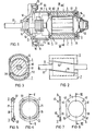
- stator housing 1 which also serves as a magnetic yoke, two magnetic shells 6, 7 are fixed to its inner wall. At the end, the stator housing 1 is closed off by a bearing plate 11 on the right side or a bearing plate 12 on the left side.
- the right end shield 11 consists of a sheet metal part and is caulked to the stator housing 1, so that there is a housing pot, in which the further assembly parts can be inserted from the left open end.
- the left end shield 12 consists of a casting to which a gear housing is coupled in a manner not shown here.
- stator housing 1 and the left end shield 12 take place via sheet metal tabs 15, 16, which can be inserted at one end into slot openings in the stator housing and with their other end protruding from the slot-shaped openings in the sense of an axial clamping of the stator housing 1 against the end shield 12 can be screwed into this via the screws 17, 18.
- Bearings 13 and 14 are held in the end shields 11 and 12, in which the shaft 81 of the rotor 8 is rotatably mounted and which projects with its left free shaft end into the gear housing (not shown here) coupled to the left end shield 12.
- the rotor laminated core 82 Concentric to the shaft 81 of the rotor 8, the rotor laminated core 82 is held at the right end of the shaft 81 and a commutator 85 is held at the left end of the shaft 81.
- the laminated core 82 receives a rotor winding, the winding heads 83, 84 of which protrude on the end face beyond the laminated core 82 of the rotor 8.
- the commutator 85 is contacted by carbon brushes 91, 92 which are mounted in a brush bridge or brush support plate 9.
- the brush support plate 9 is in the fully assembled state of the commutator motor on the one hand on the I left end face on an axially projecting collar of the Bearing childes 12 firmly and is, on the other hand, firmly pressed onto the left shaped piece 4 or 5 via molded pressure arms 93, 94.
- FIGS. 4, 5 and 6 are in plan view and sectional view, respectively Execution in Fig. 6, 7 shown.
- the two overall shaped pieces 2, 3 and 4, 5 of one end shown in FIGS. 4, 5 and 6, 7, respectively, can be a one-piece component or e.g. for manufacturing reasons, first manufactured separately as halves and then connected together, e.g. be put together.
- the overall fittings 2, 3 and 4, 5 each consist of rigid, preferably except for the lateral flattened (semi-) annular frame parts 21; 31 and 41; 51 and thereon molded elastic pressure pieces 22; 32 and 42; 52, respectively, by means of which the shaped pieces are pressed onto the magnetic shells 6, 7 axially at the front at both ends.
- a shaped piece according to FIGS. 4, 5 are made in one piece with the rigid frame parts 21 ; 31 produced elastic pressure pieces 22; 32 from fork-shaped end pieces with resilient fork tines serving as an abutment between the magnetic shell and bearing plate and, in the embodiment according to FIGS shaped pressure pieces 42, 52.
- the lateral flats adapted to the stator housing also serve for the positive tangential fixation of the shaped pieces.
- the fittings in the fully assembled state of the electrical machine are each arranged within the radial clearance between the inner wall of the stator housing 1 and the respective winding head 83 or 84 of the winding of the rotor 8, so that no additional axial installation space for fittings 2, 3 and 4, 5 is required.
Landscapes
- Engineering & Computer Science (AREA)
- Power Engineering (AREA)
- Dc Machiner (AREA)
- Permanent Field Magnets Of Synchronous Machinery (AREA)
- Motor Or Generator Frames (AREA)
- Manufacture Of Motors, Generators (AREA)
Applications Claiming Priority (2)
| Application Number | Priority Date | Filing Date | Title |
|---|---|---|---|
| DE3224414 | 1982-06-30 | ||
| DE19823224414 DE3224414A1 (de) | 1982-06-30 | 1982-06-30 | Staender fuer eine dauermagneterregte elektrische maschine und verfahren zu dessen herstellung |
Publications (2)
| Publication Number | Publication Date |
|---|---|
| EP0097875A2 true EP0097875A2 (fr) | 1984-01-11 |
| EP0097875A3 EP0097875A3 (fr) | 1985-04-10 |
Family
ID=6167230
Family Applications (1)
| Application Number | Title | Priority Date | Filing Date |
|---|---|---|---|
| EP83105872A Ceased EP0097875A3 (fr) | 1982-06-30 | 1983-06-15 | Stator pour une machine électrique excitée par aimant permanent et procédé pour sa fabrication |
Country Status (3)
| Country | Link |
|---|---|
| EP (1) | EP0097875A3 (fr) |
| DE (1) | DE3224414A1 (fr) |
| ES (1) | ES8500520A1 (fr) |
Cited By (10)
| Publication number | Priority date | Publication date | Assignee | Title |
|---|---|---|---|---|
| FR2587150A1 (fr) * | 1985-09-12 | 1987-03-13 | Mabuchi Motor Co | Boitier pour moteur electrique miniature comprenant des moyens de retenue pour aimant permanent |
| WO1987003148A1 (fr) * | 1985-11-09 | 1987-05-21 | Robert Bosch Gmbh | Machine electrique, en particulier pour systemes de demarrage de machines a combustion interne |
| GB2209880A (en) * | 1987-09-16 | 1989-05-24 | Johnson Electric Ind Mfg | Magnet retainer in an electric motor |
| EP0742635A1 (fr) * | 1995-05-11 | 1996-11-13 | Valeo Systemes D'essuyage | Moteur électrique à aimants permanents, notamment pour véhicule automobile |
| EP0782238A1 (fr) * | 1995-12-27 | 1997-07-02 | Valeo Systemes D'essuyage | Moteur à aimants permanents avec agrafes de blocage |
| FR2808937A1 (fr) * | 2000-05-11 | 2001-11-16 | Valeo Systemes Dessuyage | Machine electrique tournante |
| WO2005113991A1 (fr) * | 2004-05-21 | 2005-12-01 | Robert Bosch Gmbh | Machine electrique et procede pour relier une machine electrique a une bride de raccordement |
| WO2006092132A1 (fr) * | 2005-03-01 | 2006-09-08 | Brose Fahrzeugteile Gmbh & Co. Kg, Coburg | Systeme d'entrainement a moteur electrique |
| EP1513243A3 (fr) * | 2003-09-05 | 2007-02-14 | Robert Bosch Gmbh | Machine électrique avec des pôles à aimant permanent |
| EP2555380A3 (fr) * | 2011-08-01 | 2017-04-19 | Robert Bosch Gmbh | Machine électrique et procédé de montage d'une machine électrique |
Families Citing this family (1)
| Publication number | Priority date | Publication date | Assignee | Title |
|---|---|---|---|---|
| DE4235649A1 (de) * | 1992-10-22 | 1994-04-28 | Egon Schmid | Gleichstrom-Elektromotor mit Permanenterregung |
Family Cites Families (5)
| Publication number | Priority date | Publication date | Assignee | Title |
|---|---|---|---|---|
| DE7024970U (de) * | 1971-12-09 | Nippondenso K K | Stator für elektrische Maschinen | |
| DE109299C (fr) * | ||||
| US3234417A (en) * | 1961-11-24 | 1966-02-08 | Sperry Rand Corp | Low voltage d.c. motor |
| US3422294A (en) * | 1966-09-01 | 1969-01-14 | Gen Electric | Permanent magnet stator for dynamoelectric machines and method of assembling the same |
| DE2230707A1 (de) * | 1972-06-23 | 1974-01-10 | Adolf Schindling Gmbh | Kleinmotor |
-
1982
- 1982-06-30 DE DE19823224414 patent/DE3224414A1/de not_active Withdrawn
-
1983
- 1983-06-15 EP EP83105872A patent/EP0097875A3/fr not_active Ceased
- 1983-06-29 ES ES523693A patent/ES8500520A1/es not_active Expired
Cited By (15)
| Publication number | Priority date | Publication date | Assignee | Title |
|---|---|---|---|---|
| FR2587150A1 (fr) * | 1985-09-12 | 1987-03-13 | Mabuchi Motor Co | Boitier pour moteur electrique miniature comprenant des moyens de retenue pour aimant permanent |
| WO1987003148A1 (fr) * | 1985-11-09 | 1987-05-21 | Robert Bosch Gmbh | Machine electrique, en particulier pour systemes de demarrage de machines a combustion interne |
| GB2209880A (en) * | 1987-09-16 | 1989-05-24 | Johnson Electric Ind Mfg | Magnet retainer in an electric motor |
| GB2209880B (en) * | 1987-09-16 | 1991-11-06 | Johnson Electric Ind Mfg | Magnet retainer in an electric motor |
| EP0742635A1 (fr) * | 1995-05-11 | 1996-11-13 | Valeo Systemes D'essuyage | Moteur électrique à aimants permanents, notamment pour véhicule automobile |
| FR2734101A1 (fr) * | 1995-05-11 | 1996-11-15 | Valeo Systemes Dessuyage | Moteur electrique a aimants permanents, notamment pour vehicule automobile |
| EP0782238A1 (fr) * | 1995-12-27 | 1997-07-02 | Valeo Systemes D'essuyage | Moteur à aimants permanents avec agrafes de blocage |
| FR2743209A1 (fr) * | 1995-12-27 | 1997-07-04 | Valeo Systemes Dessuyage | Moteur a aimants permanents avec agrafes de blocage |
| US5763974A (en) * | 1995-12-27 | 1998-06-09 | Valeo Systems D'essuyage | Permanent magnet electric motors, in particular for ventilation of motor vehicles |
| FR2808937A1 (fr) * | 2000-05-11 | 2001-11-16 | Valeo Systemes Dessuyage | Machine electrique tournante |
| EP1513243A3 (fr) * | 2003-09-05 | 2007-02-14 | Robert Bosch Gmbh | Machine électrique avec des pôles à aimant permanent |
| WO2005113991A1 (fr) * | 2004-05-21 | 2005-12-01 | Robert Bosch Gmbh | Machine electrique et procede pour relier une machine electrique a une bride de raccordement |
| US7939981B2 (en) | 2004-05-21 | 2011-05-10 | Robert Bosch Gmbh | Electrical motor and method for connection of an electrical motor to a connector flange |
| WO2006092132A1 (fr) * | 2005-03-01 | 2006-09-08 | Brose Fahrzeugteile Gmbh & Co. Kg, Coburg | Systeme d'entrainement a moteur electrique |
| EP2555380A3 (fr) * | 2011-08-01 | 2017-04-19 | Robert Bosch Gmbh | Machine électrique et procédé de montage d'une machine électrique |
Also Published As
| Publication number | Publication date |
|---|---|
| ES523693A0 (es) | 1984-10-01 |
| ES8500520A1 (es) | 1984-10-01 |
| DE3224414A1 (de) | 1984-01-05 |
| EP0097875A3 (fr) | 1985-04-10 |
Similar Documents
| Publication | Publication Date | Title |
|---|---|---|
| DE2433770C2 (de) | Verfahren zum Herstellen eines Stators für eine elektrische Maschine | |
| DE2633091C3 (de) | Schwungradmagnet | |
| DE3404466C2 (fr) | ||
| EP2215703B1 (fr) | Machine à courant continu | |
| WO2002007290A2 (fr) | Ensemble rotor pour moteur electrique, et moteur electrique pourvu d'un induit interieur | |
| DE1613042A1 (de) | Elektromotor | |
| DE102010023813A1 (de) | Elektrokleinmotor | |
| DE19833802A1 (de) | Kommutator-Kleinmotor | |
| DE102020100306A1 (de) | Elektromotor aufweisend einen Rotor mit Berstschutzhülse ohne Verklebung der Magnetelemente | |
| DE2222666A1 (de) | Elektrische maschine, insbesondere kleinmotor, und vorrichtung zur herstellung dieser maschine | |
| DE19839640B4 (de) | Motor mit in einer Lageraufnahme mit Axialspieleinstellung für eine Rotorwelle fixierbarem Kalottenlager und Verfahren zur Axialspieleinstellung für eine Rotorwelle | |
| DE3224414A1 (de) | Staender fuer eine dauermagneterregte elektrische maschine und verfahren zu dessen herstellung | |
| DE102011076159A1 (de) | Elektrische Maschine mit einem axialen Federelement | |
| DE102008054330A1 (de) | Zweiteiliges Motorgehäuse mit Bajonett-Verbindung | |
| EP2102969B1 (fr) | Ensemble de carcasse de stator | |
| CH628474A5 (de) | Rotoranordnung fuer schrittschaltmotoren. | |
| EP3391509B1 (fr) | Moteur électrique | |
| EP0075777A1 (fr) | Moteur-réducteur, en particulier entraînement électromoteur de lève-glaces pour véhicules automobiles | |
| DE69631461T2 (de) | Radnabendynamo für ein Fahrrad | |
| DE3635987C2 (fr) | ||
| DE102004032423A1 (de) | Rotor und Motor, der diesen aufweist | |
| DE102006017233B4 (de) | Rotoranordnung für eine elektrische Maschine und Klauenpolmotor | |
| DE1943053A1 (de) | Elektromotor geringer Leistung | |
| EP3176438B1 (fr) | Groupe motopompe | |
| DE8218714U1 (de) | Staender fuer eine dauermagneterregte elektrische maschine |
Legal Events
| Date | Code | Title | Description |
|---|---|---|---|
| PUAI | Public reference made under article 153(3) epc to a published international application that has entered the european phase |
Free format text: ORIGINAL CODE: 0009012 |
|
| AK | Designated contracting states |
Designated state(s): DE FR GB IT |
|
| PUAL | Search report despatched |
Free format text: ORIGINAL CODE: 0009013 |
|
| AK | Designated contracting states |
Designated state(s): DE FR GB IT |
|
| 17P | Request for examination filed |
Effective date: 19850426 |
|
| 17Q | First examination report despatched |
Effective date: 19860409 |
|
| STAA | Information on the status of an ep patent application or granted ep patent |
Free format text: STATUS: THE APPLICATION HAS BEEN REFUSED |
|
| 18R | Application refused |
Effective date: 19860810 |
|
| RIN1 | Information on inventor provided before grant (corrected) |
Inventor name: FEINEIS, MANFRED |