EP0098016A2 - Procédé et circuit pour produire un signal vidéo corrigé en gamma - Google Patents
Procédé et circuit pour produire un signal vidéo corrigé en gamma Download PDFInfo
- Publication number
- EP0098016A2 EP0098016A2 EP83200927A EP83200927A EP0098016A2 EP 0098016 A2 EP0098016 A2 EP 0098016A2 EP 83200927 A EP83200927 A EP 83200927A EP 83200927 A EP83200927 A EP 83200927A EP 0098016 A2 EP0098016 A2 EP 0098016A2
- Authority
- EP
- European Patent Office
- Prior art keywords
- signal
- log
- forming
- logarithm
- equal
- Prior art date
- Legal status (The legal status is an assumption and is not a legal conclusion. Google has not performed a legal analysis and makes no representation as to the accuracy of the status listed.)
- Granted
Links
Images

Classifications
-
- H—ELECTRICITY
- H04—ELECTRIC COMMUNICATION TECHNIQUE
- H04N—PICTORIAL COMMUNICATION, e.g. TELEVISION
- H04N5/00—Details of television systems
- H04N5/14—Picture signal circuitry for video frequency region
- H04N5/20—Circuitry for controlling amplitude response
- H04N5/202—Gamma control
Definitions
- the invention relates to a method of and a circuit arrangement for producing a gamma corrected video signal.
- the video signal is transmitted in a modified form by passing the signal through a gamma correction circuit which introduces a complementary distortion.
- V s output signal for transmission
- ⁇ employed in the gamma correction circuit may not be exactly 2.5 but chosen to give the best subjectively pleasing result.
- gamma correction is to be understood to include both the correction of an uncorrected signal and the derivation of an uncorrected signal from a corrected signal.
- Gamma correction is normally achieved by first converting the input signal into its logarithm, then multiplying this signal by the desired correction factor G, and finally applying the resultant signal to an exponential or anti-logarithm converter.
- Such an arrangement is disclosed in an article entitled “Transistorised Non-Linear Function Generation” by P. Kundu and S. Banerji which was published in Industrial Electronics, January 1964 at pages 35 to 41.
- the invention provides a method of gamma correcting (as hereinbefore defined) a video signal comprising the steps of: forming a first signal representative of the logarithm of the logarithm of the video signal; forming a second signal of representative of the logarithm of the correction factor; forming a third signal representative of the algebraic sum of the first and second signals; and forming a fourth signal representative of the exponential of the exponential of the third signal, fourth signal being the gamma corrected signal.
- the invention further provides a circuit arrangement for gamma correcting (as hereinbefore defined) a video signal applied to an input thereof comprising means for forming a first signal representative of the logarithm of the logarithm of the input signal, means for forming a second signal representative of the logarithm of the correction factor, means for forming a third signal representative of the algebraic sum of the first and second signals, means for forming a fourth signal representative of the exponential of the exponential of the third signal, and means for feeding the fourth signal to an output of the circuit arrangement as the gamma corrected signal.
- a circuit arrangement for gamma correcting (as hereinbefore defined) a video signal applied to an input thereof comprising means for forming a first signal representative of the logarithm of the logarithm of the input signal, means for forming a second signal representative of the logarithm of the correction factor, means for forming a third signal representative of the algebraic sum of the first and second signals, means for forming a fourth signal representative of the
- the circuit arrangement may be such that the first signal P is equal to log B (-log A V i ) where Vi is the input signal, the second signal Q is equal to log B G where G is the correction factor, the third signal R is equal to P + Q, and the fourth signal is equal to A exp (-B exp R), where A and B are constants.
- the first, second and third means may comprise programmed digital memory devices which digital memory devices may comprise programmable read only memories.
- A 2 n where n is the number of bits in each sample of the input signal.
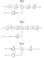
- Figure 1 illustrates the principle used in the invention for producing a modified signal which does not involve the use of multipliers and comprises an input 1 for a video signal Vi which input is connected to a log conversion unit 2 for producing a first output equal to log A Vi.
- the output of unit 2 is connected to a log conversion unit 3 for producing a second output signal equal to log B (log A Vi).
- the second output signal is applied to a first input of an adder 4.
- a correction factor G is connected via a second input 5 of the arrangement to a unit 6 which produces a third output signal equal to log B G, the third output signal being connected to a second input of-the adder 4.
- the adder 4 produces a fourth output signal equal to log B (log A V i ) + log B G which is fed to an antilog conversion unit 7 which produces a fifth output signal equal to G log A V i .
- the fifth output signal is fed to an antilog conversion unit 8 which produces a sixth output signal equal to Vi G which sixth output signal is applied to an output terminal 9 of the arrangement.
- the sign of the multiplicand may be ignored and the multiplicand treated as a positive number even though it is in fact negative. This applies in this case since the multiplicand is always negative and the multiplier G is always positive; consequently the product is always negative.
- the log and antilog conversion units may be realised as amplifiers having logarithmic and exponential characteristics respectively, the units 10 and 11 by inverting amplifiers, and the adder 4 as a summing amplifier.
- the log and antilog conversion units may be formed as programmable read only memories (PROMS) and the units 10 and 11 may be incorporated in the respective PROM since their only effect is to change the sign of the output.
- PROMS programmable read only memories
- a further simpliciation can be made as illustrated in Figure 3.
- a PROM 12 replaces units 2, 3 and 10 and a PROM 13 replaces units 4, 5 and 11. The arrangement then simplifies to three PROMS 6, 12 and 13 and an adder 4.
- the PROM 12 is programmed to give an output equal to [log B (-Iog A V i )] in response to an input signal Vi
- the PROM 6 is programmed to give an output equal to loggG in response to an input signal G
- Such an inverse operation may be useful within television camera circuits or in special effects generators.
- the dependent variable P can be made positive for all non-zero values of Vi.
- Vi may, for example, be a ten bit binary number representing values in the range
- Vi is a special case, discussed hereinafter.
- the second logarithm base, B acts as as scaling constant and is conveniently chosen such that
- the adder may overflow. This is readily detected by sensing the 'carry-out' output of the adder. In the event of overflow the output, V s , must be artificially forced to unity. Conversely, if inverse operation is being done then the state of 'underflow' of the subtractor must be sensed and the output, V s , forced artificially to zero.
Landscapes
- Engineering & Computer Science (AREA)
- Multimedia (AREA)
- Signal Processing (AREA)
- Picture Signal Circuits (AREA)
Applications Claiming Priority (4)
| Application Number | Priority Date | Filing Date | Title |
|---|---|---|---|
| GB08218883A GB2123242A (en) | 1982-06-30 | 1982-06-30 | Modifying television signals |
| GB8218883 | 1982-06-30 | ||
| GB8309208 | 1983-04-05 | ||
| GB8309208 | 1983-04-05 |
Publications (3)
| Publication Number | Publication Date |
|---|---|
| EP0098016A2 true EP0098016A2 (fr) | 1984-01-11 |
| EP0098016A3 EP0098016A3 (en) | 1986-08-20 |
| EP0098016B1 EP0098016B1 (fr) | 1990-08-29 |
Family
ID=26283235
Family Applications (1)
| Application Number | Title | Priority Date | Filing Date |
|---|---|---|---|
| EP83200927A Expired EP0098016B1 (fr) | 1982-06-30 | 1983-06-22 | Procédé et circuit pour produire un signal vidéo corrigé en gamma |
Country Status (4)
| Country | Link |
|---|---|
| US (1) | US4568978A (fr) |
| EP (1) | EP0098016B1 (fr) |
| CA (1) | CA1208769A (fr) |
| DE (1) | DE3381837D1 (fr) |
Cited By (1)
| Publication number | Priority date | Publication date | Assignee | Title |
|---|---|---|---|---|
| EP0393811A3 (fr) * | 1989-04-21 | 1992-09-30 | Sony Corporation | Correction numérique des couleurs |
Families Citing this family (13)
| Publication number | Priority date | Publication date | Assignee | Title |
|---|---|---|---|---|
| JPS6481510A (en) * | 1987-09-24 | 1989-03-27 | Hamamatsu Photonics Kk | Semiconductor integrated circuit |
| US4829381A (en) * | 1988-04-18 | 1989-05-09 | Polaroid Corporation | System and method for electronic image enhancement by dynamic pixel transformation |
| US4910465A (en) * | 1988-10-31 | 1990-03-20 | Hewlett-Packard Company | Phase detector |
| US5014013A (en) * | 1989-10-06 | 1991-05-07 | Hewlett-Packart Company | Antilog circuit with automatic gain control |
| FR2664452B1 (fr) * | 1990-07-06 | 1992-10-02 | Telediffusion Fse | Dispositif de correction de gamma sur signal video analogique. |
| US5132796A (en) * | 1990-09-04 | 1992-07-21 | Matsushita Electric Industrial Co., Ltd. | Method and apparatus for digitally processing gamma pedestal and gain |
| US5196924A (en) * | 1991-07-22 | 1993-03-23 | International Business Machines, Corporation | Look-up table based gamma and inverse gamma correction for high-resolution frame buffers |
| US5638138A (en) * | 1994-06-09 | 1997-06-10 | Hickman; Charles B. | Method for electronic image dynamic range and contrast modification |
| US6822433B1 (en) * | 2000-09-09 | 2004-11-23 | Analog Devices, Inc. | Gain and phase detector having dual logarithmic amplifiers |
| DE60130884D1 (de) * | 2001-08-10 | 2007-11-22 | Ibm | Elektronische integrierte Schaltung mit nichtlinearen Vorrichtungen |
| US7042523B2 (en) * | 2003-06-30 | 2006-05-09 | Texas Instruments Incorporated | Video correction system and method using logarithmic conversion |
| US8064716B2 (en) * | 2005-11-08 | 2011-11-22 | Soundstarts, Inc. | Apparatus and methods for enhancing digital images |
| US8538145B2 (en) | 2010-11-05 | 2013-09-17 | Apple Inc. | Gamma adjustment for maximizing information in images |
Family Cites Families (3)
| Publication number | Priority date | Publication date | Assignee | Title |
|---|---|---|---|---|
| FR2280274A1 (fr) * | 1974-07-25 | 1976-02-20 | Cit Alcatel | Chaine de transmission d'images |
| US4394688A (en) * | 1981-08-25 | 1983-07-19 | Hamamatsu Systems, Inc. | Video system having an adjustable digital gamma correction for contrast enhancement |
| US4499494A (en) * | 1982-09-27 | 1985-02-12 | Rca Corporation | Television gamma corrector with symmetrical response about black-level |
-
1983
- 1983-06-15 US US06/504,103 patent/US4568978A/en not_active Expired - Fee Related
- 1983-06-22 EP EP83200927A patent/EP0098016B1/fr not_active Expired
- 1983-06-22 DE DE8383200927T patent/DE3381837D1/de not_active Expired - Lifetime
- 1983-06-23 CA CA000431053A patent/CA1208769A/fr not_active Expired
Cited By (1)
| Publication number | Priority date | Publication date | Assignee | Title |
|---|---|---|---|---|
| EP0393811A3 (fr) * | 1989-04-21 | 1992-09-30 | Sony Corporation | Correction numérique des couleurs |
Also Published As
| Publication number | Publication date |
|---|---|
| EP0098016A3 (en) | 1986-08-20 |
| EP0098016B1 (fr) | 1990-08-29 |
| DE3381837D1 (de) | 1990-10-04 |
| US4568978A (en) | 1986-02-04 |
| CA1208769A (fr) | 1986-07-29 |
Similar Documents
| Publication | Publication Date | Title |
|---|---|---|
| EP0098016B1 (fr) | Procédé et circuit pour produire un signal vidéo corrigé en gamma | |
| JP2505798B2 (ja) | 信号過渡状態改善装置 | |
| US4233564A (en) | Apparatus for changing the scale of a logarithmic signal | |
| GB2246924A (en) | Non-linear processing of digital signals | |
| US4668989A (en) | Fading circuit for video signals | |
| US4924309A (en) | Method and circuit arrangement for improving the resolution of the coefficients of digital signals, particularly digital TV signals | |
| JPS5844883A (ja) | デイジタル色信号調整方法および装置 | |
| EP0554836A2 (fr) | Dispositif de production de forme d'onde parabolique | |
| EP0455426B1 (fr) | Circuit à caractéristiques de transfert sélectionnables | |
| IE55857B1 (en) | A method to compensate for the truncation error in a sampled signal and a device for carrying out the method | |
| CA1177174A (fr) | Memoires mortes en cascade pour traitement de signaux | |
| EP0266148B1 (fr) | Circuit de contrÔle de tonalité pour signaux numériques | |
| GB2123242A (en) | Modifying television signals | |
| JPH0795817B2 (ja) | 誤差補正付きデジタルテレビジョン信号処理装置 | |
| WO1998039913A1 (fr) | Module de traitement d'histogrammes de signaux video | |
| EP0604759B1 (fr) | Procédé et appareil pour traiter des données digitales d'image | |
| US5960122A (en) | Method of and apparatus for processing digital image data | |
| JP4446139B2 (ja) | 画像信号の自動利得制御装置及び撮像装置 | |
| SU594599A1 (ru) | Телевизионный апертурный корректор | |
| JP2705060B2 (ja) | デイジタル信号処理装置 | |
| EP0542267B1 (fr) | Circuit de correction par dispositif d'analyse d'image | |
| JPH02202774A (ja) | 画像処理装置 | |
| JP2752810B2 (ja) | 輪郭修整回路 | |
| KR930008434B1 (ko) | 코드발생에 의한 데이타 멀티플렉싱 방법 및 장치 | |
| JP2874698B2 (ja) | 非直線歪補償装置 |
Legal Events
| Date | Code | Title | Description |
|---|---|---|---|
| PUAI | Public reference made under article 153(3) epc to a published international application that has entered the european phase |
Free format text: ORIGINAL CODE: 0009012 |
|
| AK | Designated contracting states |
Designated state(s): DE FR GB |
|
| PUAL | Search report despatched |
Free format text: ORIGINAL CODE: 0009013 |
|
| AK | Designated contracting states |
Kind code of ref document: A3 Designated state(s): DE FR GB |
|
| 17P | Request for examination filed |
Effective date: 19861127 |
|
| RAP3 | Party data changed (applicant data changed or rights of an application transferred) |
Owner name: N.V. PHILIPS' GLOEILAMPENFABRIEKEN Owner name: PHILIPS ELECTRONIC AND ASSOCIATED INDUSTRIES LIMIT |
|
| 17Q | First examination report despatched |
Effective date: 19890606 |
|
| GRAA | (expected) grant |
Free format text: ORIGINAL CODE: 0009210 |
|
| AK | Designated contracting states |
Kind code of ref document: B1 Designated state(s): DE FR GB |
|
| REF | Corresponds to: |
Ref document number: 3381837 Country of ref document: DE Date of ref document: 19901004 |
|
| ET | Fr: translation filed | ||
| PG25 | Lapsed in a contracting state [announced via postgrant information from national office to epo] |
Ref country code: GB Effective date: 19910622 |
|
| PLBE | No opposition filed within time limit |
Free format text: ORIGINAL CODE: 0009261 |
|
| STAA | Information on the status of an ep patent application or granted ep patent |
Free format text: STATUS: NO OPPOSITION FILED WITHIN TIME LIMIT |
|
| 26N | No opposition filed | ||
| GBPC | Gb: european patent ceased through non-payment of renewal fee | ||
| PG25 | Lapsed in a contracting state [announced via postgrant information from national office to epo] |
Ref country code: FR Effective date: 19920228 |
|
| PG25 | Lapsed in a contracting state [announced via postgrant information from national office to epo] |
Ref country code: DE Effective date: 19920401 |