EP0098128A1 - Elastische Lagerungen - Google Patents
Elastische Lagerungen Download PDFInfo
- Publication number
- EP0098128A1 EP0098128A1 EP83303674A EP83303674A EP0098128A1 EP 0098128 A1 EP0098128 A1 EP 0098128A1 EP 83303674 A EP83303674 A EP 83303674A EP 83303674 A EP83303674 A EP 83303674A EP 0098128 A1 EP0098128 A1 EP 0098128A1
- Authority
- EP
- European Patent Office
- Prior art keywords
- membrane
- profile
- mounting
- fluid
- auxiliary
- Prior art date
- Legal status (The legal status is an assumption and is not a legal conclusion. Google has not performed a legal analysis and makes no representation as to the accuracy of the status listed.)
- Withdrawn
Links
Images

Classifications
-
- F—MECHANICAL ENGINEERING; LIGHTING; HEATING; WEAPONS; BLASTING
- F16—ENGINEERING ELEMENTS AND UNITS; GENERAL MEASURES FOR PRODUCING AND MAINTAINING EFFECTIVE FUNCTIONING OF MACHINES OR INSTALLATIONS; THERMAL INSULATION IN GENERAL
- F16F—SPRINGS; SHOCK-ABSORBERS; MEANS FOR DAMPING VIBRATION
- F16F13/00—Units comprising springs of the non-fluid type as well as vibration-dampers, shock-absorbers, or fluid springs
- F16F13/04—Units comprising springs of the non-fluid type as well as vibration-dampers, shock-absorbers, or fluid springs comprising both a plastics spring and a damper, e.g. a friction damper
- F16F13/06—Units comprising springs of the non-fluid type as well as vibration-dampers, shock-absorbers, or fluid springs comprising both a plastics spring and a damper, e.g. a friction damper the damper being a fluid damper, e.g. the plastics spring not forming a part of the wall of the fluid chamber of the damper
- F16F13/08—Units comprising springs of the non-fluid type as well as vibration-dampers, shock-absorbers, or fluid springs comprising both a plastics spring and a damper, e.g. a friction damper the damper being a fluid damper, e.g. the plastics spring not forming a part of the wall of the fluid chamber of the damper the plastics spring forming at least a part of the wall of the fluid chamber of the damper
- F16F13/10—Units comprising springs of the non-fluid type as well as vibration-dampers, shock-absorbers, or fluid springs comprising both a plastics spring and a damper, e.g. a friction damper the damper being a fluid damper, e.g. the plastics spring not forming a part of the wall of the fluid chamber of the damper the plastics spring forming at least a part of the wall of the fluid chamber of the damper the wall being at least in part formed by a flexible membrane or the like
- F16F13/103—Units comprising springs of the non-fluid type as well as vibration-dampers, shock-absorbers, or fluid springs comprising both a plastics spring and a damper, e.g. a friction damper the damper being a fluid damper, e.g. the plastics spring not forming a part of the wall of the fluid chamber of the damper the plastics spring forming at least a part of the wall of the fluid chamber of the damper the wall being at least in part formed by a flexible membrane or the like characterised by method of assembly, production or treatment
Definitions
- This invention concerns improvements in or relating to resilient mountings for connecting two components which are movable relative to each other and in particular, though not exclusively, to a resilient mounting for mounting a motor vehicle engine.
- a resilient mounting for connecting two components which are movable relative to each other comprises main and auxiliary fluid chambers which in use of the mounting contain a damping fluid between which a restrictive flow of fluid can take place upon relative movement between said components wherein the auxiliary chamber is defined at least in part by a flexible membrane of convoluted profile in the unloaded condition.
- the provision of the flexible membrane of convoluted profile in the unloaded condition of the mounting enables fluid displaced from the main chamber to be accommodated by unfolding of the membrane to increase the volume of the auxiliary chamber up to a predetermined limit without stretching the membrane and thereby not subjecting it to high tensile stresses.
- the membrane is constructed to accommodate the fluid displaced from the main chamber under the static load and more preferably the volume displaced under both the static load and the dynamic loads encountered in use without any significant stretching thereof.
- the main and auxiliary chambers are separated by a partition wall which may be rigid or flexible and which contains one or more throttling apertures for controlling the flow of fluid between the chambers.
- auxiliary chamber is contained within a rigid inner support member which is adapted for connection to one of the two components to be connected.
- the main chamber is defined at least in part by an elastomeric spring which acts between an external surface of the inner support member and an inner surface of an outer support member which is adapted for connection to the other of the two components to be connected.
- said external and internal surfaces are of frusto-conical shape.
- the partition wall is positioned at the inner end of the inner support member.
- the flexible membrane may be annular having a centre region thereof deflected towards the partition wall in the unloaded condition and movable away from the partition wall to increase the volume of the auxiliary chamber.
- the membrane may have other convoluted constructions in the unloaded condition so as to provide an auxiliary chamber the volume of which is variable.
- the membrane, inner support member, spring and outer support member are formed as an integral fully bonded unit.
- the membrane as moulded has a profile substantially similar to that which it adopts under static loading of the mounting and is deflected to a convoluted profile in the unloaded condition.
- the membrane as moulded is of convoluted profile to enable the volume contained therein to be increased beyond the as moulded volume without stretching the membrane.
- the membrane may be generally cup-shaped as moulded with a recessed or concave portion in the base.
- the inner and outer support members are provided with respective end plates having means for attachment to the components.
- the end plate attached to the outer support member completes the main fluid chamber and the end plate attached to the inner support member forms a space within the inner member on the opposite side of the membrane to the auxiliary chamber.
- Such space may have a volume in the unloaded condition of the mounting substantially equal to the amount by which the auxiliary chamber may increase in volume without stretching the membrane thereby providing a positive limit to deflection of the membrane.
- the space may be closed .or open to atmosphere.
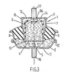
- the resilient mounting 1 shown in Figure 1 of the accompanying drawings comprises main and auxiliary fluid chambers 2 and 3 respectively each containing hydraulic damping fluid, e.g. silicone, and separated by a rigid partition wall 4 having a central aperture 5 to permit a restricted flow of damping fluid between the chambers 2,3.
- hydraulic damping fluid e.g. silicone
- Main chamber 2 is defined at least in part by an annular rubber spring 6 acting between and bonded to confronting external and internal frusto-conical surfaces 7a and 8a respectively of rigid inner and.outer support members 7 and 8 and auxiliary chamber 3, contained within the inner support member 7, is defined at least in part by an annular rubber membrane 9 bonded at the peripheral edge thereof to the internal frusto-conical surface 7b of the inner support member 7.
- the rigid partition wall 4 separating the main and auxiliary chambers is positioned at the narrower inner end of the internal support member 7 and secured by deforming the end of the support member 7 to form an annular groove 10 in which the peripheral edge of the partition wall 4 is received.
- An annular end plate 11 positioned at the narrower outer end of the outer support member 8 completes the main chamber 2 and is secured by deforming the end of the support member 8 to form an annular groove 12 in which the peripheral edge of the end plate ll is received.
- An annular end plate 13 positioned at the wider outer end of the inner support member 7 forms a space 14 within the support member 7 and is secured by deforming the end of the support member 7 to form an annular groove 15 in which the peripheral edge of the end plate 13 is received.
- Space 14 is open to atmosphere through one or more apertures (not shown) formed in end plate 13.
- Each end plate 11 and 13 is provided with an integral axial extending shank 16 and 17 respectively which is externally threaded for securing each end plate to a respective one of two components to be connected.
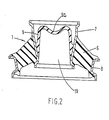
- FIG. 2 there is shown an integral fully bonded unit 18 consisting of the membrane 9, inner support member 7, spring 6 and outer support member 8 to which the partition wall 4 and end plates 11 and 13 may subsequently be attached by deforming the end portions of the supporting members as above described.
- membrane 9 has a generally cup-shaped profile in which base 9a is adjacent the outer end of the inner support member.
- the internal volume 19 defined by the membrane 9 which in use contains the damping fluid is less than the internal volume of the inner support member and the centre region of the base 9a is of recessed or concave profile such that the centre region may deflect in use to increase the internal volume 19 beyond the as moulded volume without greatly stretching the membrane and therefore without generating significant tensile stresses therein.
- membrane 9 On assembly membrane 9 is deflected from its as moulded profile to the convoluted profile shown in Figure 1 in which base 9a is adjacent to the inner end of the inner support member by applying a predetermined axial load to one of the support members to compress spring 6 and reduce the volume of main chamber 2 prior to the introduction of the damping fluid through a suitable inlet (not shown) in end plate 11.
- a suitable inlet not shown
- the mounting for example as a resilient mounting for a vehicle engine in which end plate 13 is secured to the vehicle engine (not shown) and end plate 11 is secured to the vehicle body (not shown) or vice versa relative axial movement between the inner and outer support members such as to compress spring 6 simultaneously reduces the volume of the main chamber 2 and forces damping fluid through the throttling aperture 5 in the partition wall 4 into the auxiliary chamber 3 where it is accommodated by deflection of the membrane 9 to increase the volume of the auxiliary chamber 3.
- the mounting 1 above described is constructed so that under static loading of the mounting the volume of damping fluid forced through the aperture 5 into the auxiliary chamber 3, deflects the membrane 9 to the position shown in Figure 3 in which the membrane has a profile substantially similar to that in the as moulded condition of the unit 18 shown in Figure 2.
- tensile stress levels generated in the membrane 9 are kept to a minimum under static loading.
- the base 9a of membrane 9 is still of recessed or concave profile under static loading such that deflection of membrane 9 may occur to increase further the volume of the auxiliary chamber to accommodate fluid forced through the aperture 5 due to variations in the dynamic loads produced by vibrational movement of the engine without sign- nificantly stretching the membrane.
- tensile stress levels generated in the membrane '9 are also kept to.a minimum under dynamic loading.
- a membrane having a convoluted profile in the unloaded condition which is capable of accommodating displaced fluid without being significantly stretched not only improves the fatigue life of the membrane by avoiding high tensile stressing thereof but also enables maximum use to be made of the space available in the inner support member for containing fluid displaced from the main chamber since the inner support member does not have to have an internal volume significantly greater than the as moulded volume of the membrane to allow stretching of the latter under both static and dynamic loads to increase the volume of the auxiliary chamber.
- the membrane 9 may have any convoluted profile, e.g. a bellows type profile, which enables the volume of the auxliary chamber to be varied without significantly stretching the membrane.
- the deflection of the membrane from its moulded profile on assembly may be such that it reverts substantially to its as moulded profile under any desired applied load e.g. the static load as above described, the maximum static and dynamic load to which it may be subjected in use or any intermediate load.
- the increase in volume of the auxiliary chamber which may occur without significantly stretching the membrane may be controlled either by ensuring the volume of space 14 does not greatly exceed such increase in volume or by providing an end stop to limit axial movement between the support members such that the volume of fluid displaced from the main chamber does not greatly exceed such increase in volume.
- the partition wall 4 may have more than one throttling aperture 5 and the or each aperture may be constructed to provide any required damping characteristic. Further the partition wall 4 may be rigid as described or flexible and may be fixed as described or mounted for movement relative to the inner support member in known manner.
- the support members 7,8 may be made from metal or any other suitable material e.g. reinforced plastics.
- spring 6 and membrane 9 may be made from any elastomeric material ' compatible with the damping fluid which may also be of any known type.
- the required convoluted profile for membrane 9 in the unloaded condition of the mounting may be achieved by methods other than the preloading of the mounting above described.
- the membrane may be deflected to the required profile by a former prior to introducing the damping fluid.
- the rubber spring 6 may contain a reinforcement e.g. one or more metal plates or other substantially inextensible material.
- the inner and/or outer members 7 and 8 may be adapted for connection to a component by means other than shanks 16 and 17 e.g. end plates 11 and 13 may be adapted to include holes or studs for attaching the end plate to a component.
Landscapes
- Engineering & Computer Science (AREA)
- General Engineering & Computer Science (AREA)
- Manufacturing & Machinery (AREA)
- Mechanical Engineering (AREA)
- Combined Devices Of Dampers And Springs (AREA)
Applications Claiming Priority (2)
| Application Number | Priority Date | Filing Date | Title |
|---|---|---|---|
| GB8218512 | 1982-06-25 | ||
| GB08218512A GB2122718A (en) | 1982-06-25 | 1982-06-25 | Fluid damped resilient mountings |
Publications (1)
| Publication Number | Publication Date |
|---|---|
| EP0098128A1 true EP0098128A1 (de) | 1984-01-11 |
Family
ID=10531293
Family Applications (1)
| Application Number | Title | Priority Date | Filing Date |
|---|---|---|---|
| EP83303674A Withdrawn EP0098128A1 (de) | 1982-06-25 | 1983-06-24 | Elastische Lagerungen |
Country Status (2)
| Country | Link |
|---|---|
| EP (1) | EP0098128A1 (de) |
| GB (1) | GB2122718A (de) |
Cited By (3)
| Publication number | Priority date | Publication date | Assignee | Title |
|---|---|---|---|---|
| EP0191703A1 (de) * | 1985-02-15 | 1986-08-20 | Hutchinson | Änderungen an hydraulischen Antischwingungslagern |
| EP0384966A3 (en) * | 1989-03-01 | 1990-11-14 | Firma Carl Freudenberg | Engine mounting |
| EP1584837A1 (de) * | 2004-04-08 | 2005-10-12 | Hutchinson | Schwingungsdämpfungseinrichtung |
Families Citing this family (5)
| Publication number | Priority date | Publication date | Assignee | Title |
|---|---|---|---|---|
| DE3443618A1 (de) * | 1984-11-29 | 1986-06-05 | Metzeler Kautschuk GmbH, 8000 München | Motorlager mit hydraulischer daempfung |
| FR2578609B1 (fr) * | 1985-03-11 | 1989-04-28 | Hutchinson | Dispositif de suspension hydroelastique pour plates-formes mobiles de forage auto-elevatrices |
| JP2693434B2 (ja) * | 1986-12-29 | 1997-12-24 | 株式会社ブリヂストン | サスペンション用減衰力発生装置およびそれの作動制御装置 |
| JP3438561B2 (ja) | 1997-12-26 | 2003-08-18 | 東海ゴム工業株式会社 | 液体封入式防振装置 |
| US7007934B2 (en) | 2001-07-02 | 2006-03-07 | Tokai Rubber Industries, Ltd. | Fluid-filled vibration damping device |
Citations (8)
| Publication number | Priority date | Publication date | Assignee | Title |
|---|---|---|---|---|
| FR2274833A1 (fr) * | 1974-06-11 | 1976-01-09 | Lord Corp | Isolateur a amortissement par fluide |
| GB2033534A (en) * | 1978-10-13 | 1980-05-21 | Gould Inc | Combined elastomeric spring and fluid damper |
| DE2932478A1 (de) * | 1979-08-10 | 1981-02-26 | Freudenberg Carl Fa | Hydrolager |
| FR2472116A1 (fr) * | 1979-12-13 | 1981-06-26 | Continental Gummi Werke Ag | Palier elastique |
| FR2475172A1 (fr) * | 1980-01-31 | 1981-08-07 | Bridgestone Tire Co Ltd | Isolateur anti-vibrations en caoutchouc |
| DE3016421A1 (de) * | 1980-04-29 | 1981-11-05 | Phoenix Ag, 2100 Hamburg | Elastisches lager mit hydraulischer daempfung |
| EP0042911A2 (de) * | 1980-06-27 | 1982-01-06 | Boge GmbH | Hydraulisch dämpfendes Einkammerlager |
| EP0053401A1 (de) * | 1980-12-03 | 1982-06-09 | Nissan Motor Co., Ltd. | Mit einem Fluidum gefülltes Motorlager |
Family Cites Families (6)
| Publication number | Priority date | Publication date | Assignee | Title |
|---|---|---|---|---|
| BE535270A (de) * | 1954-02-10 | |||
| GB811748A (en) * | 1956-07-31 | 1959-04-08 | Metalastik Ltd | Improvements in or relating to vibration dampers |
| US3658314A (en) * | 1969-08-18 | 1972-04-25 | Clevite Corp | Elastomeric fluid shock absorber |
| US3751091A (en) * | 1971-08-18 | 1973-08-07 | Chrysler Corp | Energy absorbing bumper support |
| DE2727244C2 (de) * | 1976-06-30 | 1990-06-21 | Automobiles Peugeot, 75116 Paris | Gummifeder mit Flüssigkeitsfüllung |
| DE2906282C2 (de) * | 1979-02-19 | 1982-12-09 | Boge Gmbh, 5208 Eitorf | Hydraulisch dämpfendes Einkammerlager |
-
1982
- 1982-06-25 GB GB08218512A patent/GB2122718A/en not_active Withdrawn
-
1983
- 1983-06-24 EP EP83303674A patent/EP0098128A1/de not_active Withdrawn
Patent Citations (8)
| Publication number | Priority date | Publication date | Assignee | Title |
|---|---|---|---|---|
| FR2274833A1 (fr) * | 1974-06-11 | 1976-01-09 | Lord Corp | Isolateur a amortissement par fluide |
| GB2033534A (en) * | 1978-10-13 | 1980-05-21 | Gould Inc | Combined elastomeric spring and fluid damper |
| DE2932478A1 (de) * | 1979-08-10 | 1981-02-26 | Freudenberg Carl Fa | Hydrolager |
| FR2472116A1 (fr) * | 1979-12-13 | 1981-06-26 | Continental Gummi Werke Ag | Palier elastique |
| FR2475172A1 (fr) * | 1980-01-31 | 1981-08-07 | Bridgestone Tire Co Ltd | Isolateur anti-vibrations en caoutchouc |
| DE3016421A1 (de) * | 1980-04-29 | 1981-11-05 | Phoenix Ag, 2100 Hamburg | Elastisches lager mit hydraulischer daempfung |
| EP0042911A2 (de) * | 1980-06-27 | 1982-01-06 | Boge GmbH | Hydraulisch dämpfendes Einkammerlager |
| EP0053401A1 (de) * | 1980-12-03 | 1982-06-09 | Nissan Motor Co., Ltd. | Mit einem Fluidum gefülltes Motorlager |
Cited By (5)
| Publication number | Priority date | Publication date | Assignee | Title |
|---|---|---|---|---|
| EP0191703A1 (de) * | 1985-02-15 | 1986-08-20 | Hutchinson | Änderungen an hydraulischen Antischwingungslagern |
| FR2577641A1 (fr) * | 1985-02-15 | 1986-08-22 | Hutchinson | Perfectionnements aux supports antivibratoires hydrauliques |
| EP0384966A3 (en) * | 1989-03-01 | 1990-11-14 | Firma Carl Freudenberg | Engine mounting |
| EP1584837A1 (de) * | 2004-04-08 | 2005-10-12 | Hutchinson | Schwingungsdämpfungseinrichtung |
| FR2868821A1 (fr) * | 2004-04-08 | 2005-10-14 | Hutchinson Sa | Dispositif antivibratoire |
Also Published As
| Publication number | Publication date |
|---|---|
| GB2122718A (en) | 1984-01-18 |
Similar Documents
| Publication | Publication Date | Title |
|---|---|---|
| US5246212A (en) | Fluid-filled elastic mount having vacuum-receiving chamber and auxiliary air chamber for accommodating volumetric change of equilibrium chamber | |
| US6758466B2 (en) | Fluid-elastomeric damper assembly including internal pumping mechanism | |
| US5145156A (en) | Fluid-filled elastic mount having two differently tuned orifices selectively utilized for damping or isolating vibrations in different frequency ranges | |
| US4733854A (en) | Fluid sealed mounting | |
| US4215842A (en) | Rubber elastic engine mounts or supports with hydraulic damping | |
| KR100191104B1 (ko) | 부싱형 진동 댐핑 장치 | |
| US4029305A (en) | Pneumatic vibration isolator and suspension system | |
| EP0077195A2 (de) | Stoss- und Schwingungsdämpfer aus Elastomeren | |
| GB2087511A (en) | Self-leveling fluid damped elastomeric spring unit | |
| US5242158A (en) | Adjustable hydroelastic mounting | |
| EP0053401A1 (de) | Mit einem Fluidum gefülltes Motorlager | |
| CZ27996A3 (en) | Bearing | |
| CA2021986C (en) | Hydraulically dampened engine mount | |
| EP0322239B1 (de) | Hydraulisch gedämpfte Lagervorrichtung | |
| EP0460529B1 (de) | Hydraulisch gedämpfte Vorrichtung | |
| GB2122718A (en) | Fluid damped resilient mountings | |
| GB2152182A (en) | Hydraulically damped two-chamber bearing structure | |
| US4767107A (en) | Central suspension hydroelastic mount, in particular for the suspension of a motor-vehicle motor-drive unit | |
| CN110360266B (zh) | 液压悬置装置及分离件 | |
| JP2813582B2 (ja) | 流体制振ブロック | |
| JP3505475B2 (ja) | 液圧減衰軸受 | |
| US5853063A (en) | Engine mount for motor vehicles | |
| US5687959A (en) | Hydraulically damping rubber bearing | |
| US5816566A (en) | Viscous fluid mount | |
| US6220584B1 (en) | Hydraulically damping engine bearing |
Legal Events
| Date | Code | Title | Description |
|---|---|---|---|
| PUAI | Public reference made under article 153(3) epc to a published international application that has entered the european phase |
Free format text: ORIGINAL CODE: 0009012 |
|
| AK | Designated contracting states |
Designated state(s): DE FR IT NL SE |
|
| 17P | Request for examination filed |
Effective date: 19840518 |
|
| STAA | Information on the status of an ep patent application or granted ep patent |
Free format text: STATUS: THE APPLICATION IS DEEMED TO BE WITHDRAWN |
|
| 18D | Application deemed to be withdrawn |
Effective date: 19870101 |
|
| RIN1 | Information on inventor provided before grant (corrected) |
Inventor name: RANDELL, WILLIAM FRANCIS |