EP0098344A1 - Dispositif et procédé de traitement thermique - Google Patents
Dispositif et procédé de traitement thermique Download PDFInfo
- Publication number
- EP0098344A1 EP0098344A1 EP83102033A EP83102033A EP0098344A1 EP 0098344 A1 EP0098344 A1 EP 0098344A1 EP 83102033 A EP83102033 A EP 83102033A EP 83102033 A EP83102033 A EP 83102033A EP 0098344 A1 EP0098344 A1 EP 0098344A1
- Authority
- EP
- European Patent Office
- Prior art keywords
- stay
- spaces
- materials
- space
- treatment
- Prior art date
- Legal status (The legal status is an assumption and is not a legal conclusion. Google has not performed a legal analysis and makes no representation as to the accuracy of the status listed.)
- Granted
Links
- 238000010438 heat treatment Methods 0.000 title claims abstract description 62
- 238000000034 method Methods 0.000 title claims abstract description 15
- 230000008569 process Effects 0.000 title claims abstract description 15
- 239000000463 material Substances 0.000 claims abstract description 83
- 238000001816 cooling Methods 0.000 claims abstract description 44
- 238000011282 treatment Methods 0.000 claims description 36
- 238000010276 construction Methods 0.000 claims description 8
- 238000007599 discharging Methods 0.000 claims description 6
- 239000002184 metal Substances 0.000 claims description 2
- 230000007246 mechanism Effects 0.000 description 9
- 238000005192 partition Methods 0.000 description 7
- 239000002826 coolant Substances 0.000 description 3
- 230000004048 modification Effects 0.000 description 2
- 238000012986 modification Methods 0.000 description 2
- 229910000831 Steel Inorganic materials 0.000 description 1
- 235000019628 coolness Nutrition 0.000 description 1
- 239000007789 gas Substances 0.000 description 1
- 238000012423 maintenance Methods 0.000 description 1
- 239000007769 metal material Substances 0.000 description 1
- 230000008439 repair process Effects 0.000 description 1
- 238000007789 sealing Methods 0.000 description 1
- 239000010959 steel Substances 0.000 description 1
Images

Classifications
-
- F—MECHANICAL ENGINEERING; LIGHTING; HEATING; WEAPONS; BLASTING
- F27—FURNACES; KILNS; OVENS; RETORTS
- F27B—FURNACES, KILNS, OVENS OR RETORTS IN GENERAL; OPEN SINTERING OR LIKE APPARATUS
- F27B9/00—Furnaces through which the charge is moved mechanically, e.g. of tunnel type; Similar furnaces in which the charge moves by gravity
- F27B9/14—Furnaces through which the charge is moved mechanically, e.g. of tunnel type; Similar furnaces in which the charge moves by gravity characterised by the path of the charge during treatment; characterised by the means by which the charge is moved during treatment
- F27B9/16—Furnaces through which the charge is moved mechanically, e.g. of tunnel type; Similar furnaces in which the charge moves by gravity characterised by the path of the charge during treatment; characterised by the means by which the charge is moved during treatment the charge moving in a circular or arcuate path
-
- C—CHEMISTRY; METALLURGY
- C21—METALLURGY OF IRON
- C21D—MODIFYING THE PHYSICAL STRUCTURE OF FERROUS METALS; GENERAL DEVICES FOR HEAT TREATMENT OF FERROUS OR NON-FERROUS METALS OR ALLOYS; MAKING METAL MALLEABLE, e.g. BY DECARBURISATION OR TEMPERING
- C21D1/00—General methods or devices for heat treatment, e.g. annealing, hardening, quenching or tempering
- C21D1/26—Methods of annealing
- C21D1/32—Soft annealing, e.g. spheroidising
-
- C—CHEMISTRY; METALLURGY
- C21—METALLURGY OF IRON
- C21D—MODIFYING THE PHYSICAL STRUCTURE OF FERROUS METALS; GENERAL DEVICES FOR HEAT TREATMENT OF FERROUS OR NON-FERROUS METALS OR ALLOYS; MAKING METAL MALLEABLE, e.g. BY DECARBURISATION OR TEMPERING
- C21D9/00—Heat treatment, e.g. annealing, hardening, quenching or tempering, adapted for particular articles; Furnaces therefor
- C21D9/0037—Rotary furnaces with vertical axis; Furnaces with rotating floor
Definitions
- This invention relates to systems for heat-treating metal materials such as steel or other kinds of materials by repeating alternate treatments of heating and cooling the material a number of times, and a process for heat-treating the materials of the kinds stated by using the above-mentioned systems.
- One of the conventional types of heat-treatment systems as stated above includes a number of heating chambers and cooling chambers arranged so as to alternate with the other ones along the direction in which to convey the material to be treated. In such a construction it is no small trouble to keep each treatment chamber in a good state of repair.
- An object of the invention is to provide a heat-treatment system including no more than one heating chamber and one cooling chamber, thereby making the whole maintenance of the system a simpler work.
- Another object of the invention is to provide a heat-treatment system including no more than one heating chamber and one cooling chamber, but making it possible to alternately heat and cool the material a number of times, and a process for such a heat treatment.
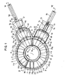
- an annular furnace body 1 is constructed of an enclosure 3 and a hearth 4, and includes a circular heat-treatment space 5 in which there is set a travel locus 2 to be generated by the materials (to be treated) when they are circulated (as described herein after).
- the enclosure 3 is fixed to a floor 6 by support means (not shown).
- the hearth 4 is adapted to rotate along the material-travel locus 2 by means of a number of operating wheels 7. Both enclosure 3 and hearth 4 are so constructed as to minimize a heat loss from the treatment space 5.
- sealing means 8 well-known in the art for keeping gases within the treatment space 5 from escaping.
- the treatment space 5 is divided into a heating chamber 9 and a cooling chamber 10 separated from each other by doors 28 and 29 (hereafter described) and arranged along the travel locus 2.
- a heating chamber 9 and a cooling chamber 10 separated from each other by doors 28 and 29 (hereafter described) and arranged along the travel locus 2.
- These stay spaces lla to 11g are also arranged along the material-travel locus 2.
- the number of the stay spaces lla to 11g is set at the sum of twice the number of heat treatments to be made for the material (one treatment consisting of a whole process of heating and cooling) and 1 (one).
- the number of the stay spaces lla to 11g is set at 7 (seven) in this embodiment.
- the stay spaces lla, llb, and 11c are located in the heating chamber 9, while the other stay spaces lle, llf, and 11 g are located in the cooling chamber 10.
- the stay space lid is in the cooling chamber 10 in the embodiment herein, however, it may be located in the other chamber 9 by disposing the partition door 28 between the stay spaces lid and 11e instead of 11c and lld, or it also may be located in a place not belonging to the chambers 9 or 10 by disposing another door between the spaces 11d and lle, in addition to those 28 and 29.
- the section of the furnace enclosure 3 defining the heating chamber 9 is provided with a heating means 14 such as a burner or electrothermal means. Also, an air.circulator 15 such as a fan is connected to the same section in conjunction with a motor 16 for operating the air circulator 15.
- the section of the furnace enclosure 3 defining the cooling chamber 10 is provided with a cooling means 17 such as an opening for supplying a cooling medium into the chamber 10 and a combination of air circulator 18 (such as a fan) and motor 19 for operating the air circulator; 18.
- the cooling medium to be supplied through the opening 17 may be air.
- the furnace enclosure 3 is also provided with an outlet (not shown) for discharging the air supplied into the cooling space 10.
- the movable hearth 4 On the upper surface of the movable hearth 4 are set or determined areas 20 1 , 20 2 , 20 3 , 20 4 , 20 5 , 20 6 , and 20 7 which are provided in the same number as the material-stay spaces lla to 11g and spaced apart from one another at the same intervals as the stay spaces and on which are to be placed baskets 21 containing materials to be treated.
- These material places 20 1 to 20 2 each are provided with a pair of rails 22 on which to locate the baskets 21
- a means 23 for rotating the hearth 4 which comprises a rack 24 connected to the hearth 4 at the entire outer edge of the lower surface thereof, a motor 25 disposed on the floor 6 and having a shaft 26, and a gear 27 connected to the shaft 26 and meshing with the rack 24.
- the motor 25 When the motor 25 is operated, therefore, the hearth 4 rotates along the material-travel rocus .2.
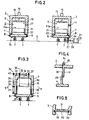
- the partition door 28 can be moved in vertical directions along and between a pair of grooves 30 which are oppositely provided in the inner surfaces of the inner and outer walls of the furnace enclosure 3, respectively.
- a partition wall 31 projects downward from the top of the enclosure 3 into the treatment space 5 and in a position adjacent to that of the door 28 when the door 28 is raised (Fig. 4).
- the partition wall 31 only extends halfway, but completely separates the two treatment chambers 9 and 10 from each other, together with the door 28, when the door 28 is in its lowered position.
- a mechanism 32 for raising or lowering the door 28 which mechanism 32 includes a drive shaft 34 supported by bearings 33 connected to the top of the enclosure and a cylinder 37 connected to the outer surface of the outer wall of the enclosure 3.
- the drive shaft 34 has three sprocket wheels 35 and 40, and chains 36 are fitted onto the sprocket wheels 35, respectively, at their upper ends while the chains 36 are connected to the top of the door 28 at their lower ends.
- the cylinder 37 has a piston rod 38, and a chain 39 is connected to the piston rod 38 at its lower end and fitted onto the outermost sprocket wheel 40 of the drive shaft 34 at its upper end.
- the drive shaft 34 is rotated to raise or lower the door 28.
- the other partition door 29 is also adapted to rise or lower by the same mechanism as for the door 28.
- a preheater device 42 is connected to the furnace body 1.
- the preheater device 42 includes a preheating chamber 46 defined by a furnace body 45 and a hearth 44 fixed to the floor 6 by supports 43. As with the furnace body 1, both hearth 44 and furnace body 45 are so constructed as to minimize a heat loss from the preheating chamber 46.
- the preheater device 42 is provided with a heating means (not shown), fan 47, and motor 48 similar to those of the heating chamber 9.
- a pair of rails 49 are located on the hearth 44.
- the preheater device 42 is connected to a portion of the heating chamber 9 of the furnace body 1, and as shown in Fig.
- That portion or a portion of the outer wall of the chamber 9 has an opening 50 at its lower end.
- This opening 50 is closed by a movable partition door 51 which is raised to move a basket from the preheating chamber 46 to the heating chamber 9, allowing the former chamber 46 to communicate with the latter 9.
- the mechanism to raise or lower the door 51 is similar to that for the door 28 or 29. Also, all other similar doors that will be described hereinafter are operated by similar mechanisms.
- another opening 52 is oppositely provided in the preheater device 42. Similarly, this opening 52 is closed by a door 53, but is opened to move a basket 21 from outside into the chamber 46 by raising the door 53.
- a table 54 for supplying baskets 21 (containing materials to be treated) into the preheater device 42 is located outside the device 42 in close proximity to the opening 52 of the device 42.
- On the table 54 are provided a pair of rails 55 on which are placed a basket 21 and a cylinder 56 for moving the basket 21.
- the cylinder 56 has a piston rod 57 with a pair of pushers 58 and 59.
- the piston 57 is moved forward with the pusher 58 moving the basket 21 placed on the table 54 into the preheater device 42 and with another pusher 59 moving the basket 21 in the device 42 (i.e., one previously loaded into the device 21) into the material-stay space lla of the heating chamber 9.
- the forward pusher 59 is brought down in a direction indicated by an arrow in Fig. 6, and allowed to move back under the basket 21 loaded into the preheater device 42.
- a cooler device 61 is connected to the furnace body 1 (Fig. 1 and 7).
- the cooler device 61 includes a cooling chamber 65 defined by a cooler body 64 and a cooler floor 63 located on the floor 6 by supports 62.
- a pair of rails 66 are provided on the cooler floor 63.
- the cooler body 64 is provided with an inlet for supplying a cooling medium (not shown), a fan 67, and a motor 68 for operating the fan 67.
- the cooler device 61 is connected to a portion of the cooling chamber 10 of the furnace body 1, and as with the heating chamber 9, that portion or a portion of the outer wall of the cooling chamber 10 has an opening 69 at its lower end.
- the opening 69 is closed by a movable partition door 70 which is raised to move a basket 21 from the cooling chamber 10 to another cooling chamber 65, allowing the former chamber 10 to communicate with the latter 65.
- another opening 71 is oppositely provided in the cooler device 61 for discharging a basket 21 from the cooler device 61.
- this opening 71 is closed by a door 72, but is opened to discharge the basket 21 by raising the door 72.
- a table 73 for discharging the basket 21 is located outside the cooler device 61 in close proximity to the discharge opening 71 of the device 61. On the table 73 are arranged a pair of rails 74 and a cylinder 75.
- the cylinder 75 has a piston rod 76 with a pair of drawer means 77 and 78.
- the drawer means 77 and 78 are brought down in directions indicated by arrows in Fig. 7 and travel to their respective draw positions in the chambers 65 and 10 without coming into contact with the baskets placed in those chambers. Then, both drawer means are erected in the chambers, and the piston rod 76 is retracted to cause the means 77 to draw out the basket in the cooler device 61 and the other means 78 to move the basket in the stay space llg (of the cooling chamber 10) into the cooler device 61.
- a basket 21 containing a material to be treated is first placed on the rails 55 of the supply table 54. Then the door 53 is opened, the basket 21 is moved into the preheater device 42 by the pusher 58, and the door 53 is closed. In this device 42 the material in the basket 21 is heated to a predetermined temperature, such as 700°C. After it has been heated, the doors 51 and 53 are opened, and the basket 21 is moved from the device 42 onto the material area 20 1 on the movable hearth 4 by means of the pusher 59. Simultaneously with the foregoing process, another basket 21 is similarly placed on the table 54 and moved into the preheater device 42 by the pusher 58. Then the doors 51 and 53 are both closed.
- the heating means 14 and the air circulator 15 are operated to heat the material in the basket 21 placed in the area 20 1 or stay space lla to a predetermined temperature, such as 750°C. Simultaneously the material placed in the preheater device 42 is heated as already mentioned. Then the doors 28 and 29 are raised or opened, and the hearth 4 is rotated three steps clockwise (or four steps counterclockwise) by the rotation mechanism 23 so that the area 20 1 reaches the material-stay space lle. The doors 28 and 29 are both closed, and the material thus located in the stay space lie is cooled to a predetermined temperature, such as 700°C.
- the foregoing second basket 21 is placed on the material-placing area 20 4 then located in the material-stay space lla, and the material therein is heated to the predetermined temperature.
- the doors 28 and 29 are opened, and the hearth 4 is rotated, e.g., the same steps as before clockwise so that the areas 20 1 and 20 4 move to the stay spaces llb and lle, respectively.
- the doors 28 and 29 are closed again.
- the material located in the stay space llb is heated again to a predetermined temperature, such as 745°C, while that in the stay space lie is cooled to 700°C.
- a still further basket 21 containing a material is placed on the area 20 7 then located in the stay space lla, and that material is heated therein.
- the material in the area 20 1 is further moved to and stayed in the spaces llf, llc, and 11g for further treatment. To sum up, therefore, the material is subjected to alternaten treatments of heating and cooling by staying in the spaces lla, lle, llb, llf, llc, and 11g in the order mentioned. In other words, the material is heated three times and cooled three times.
- the door 70 is opened and the basket 21 is moved onto the rails 66 of the cooler device 61 by the drawer means 78. Then the door 70 is closed, and the material thus located in the device 61 is gradually cooled to a predetermined temperature, such as 650°C (at a rate of 60°C or so per hour).
- a predetermined temperature such as 650°C (at a rate of 60°C or so per hour).
- the hearth 4 is rotated to move the area 20 1 then having no material to the stay space lld.
- the area 20 1 is returned to the starting space lla.
- a material loaded on one of the areas 20 1 to 20 7 via the preheater device 42 is treated in the same manner as those loaded on the other areas, i.e., subjected to alternate heating and cooling in the same number of times and the same temperatures as those materials.
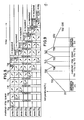
- This process is illustrated in a table of Fig.
- the body may be located, e.g., in a corner of the plant so that the whole area of the plant is utilized with the maximum density.
- Fig. 9 shows variations of the temperature of the material which are effected when the material is heat-treated as described before; it is seen that the material is heated to a temperature of 700°C in the preheater device 42, subjected to alternate treatments of heating and cooling to the temperatures indicated, gradually cooled in the cooler device 61, and finally cooled to the normal temperatures on the discharge table (or at some other desired place).
- Such a particular process of heat treatment may be used to spheroidize metal, for example.
- hearth 4 has been described as being rotated intermittently in one direction (clockwise) and by equal angles or steps (3 steps), its rotational direction may be opposite as stated before or alternated with the other one so as to move the materials into stay spaces desired.
- cooler device 61 and its associated material-discharge opening 69 may be located in combination with the stay space lid instead of 11g. If such a modification is made, the material finally cooled in the space llg is discharged after it has been moved into the stay space lid by the next rotation of the hearth 4. In such a modification, materials to be treated are loaded into the system on one side thereof and unloaded therefrom on its other side.
- the system of such a construction may be adaptable for use in a line operation.
- the process herein has been described as comprising three alternations of heating and cooling of each material, requiring seven stay spaces to be set. However, if a process of heating and cooling is to be carried out twice, five stay spaces (and five material areas) are set according to the principle as stated before. Similarly, if four alternations are to be made, nine stay spaces (and nine material areas) are set. That is, the principle to determine the number of stay spaces and material areas required is represented by the general formula (2 n + 1) where n is the number of times of alternations of treatments to be made. The minimum number of the stay spaces to be set in each chamber 9 or 10 is n, and one remaining space may be made additionally to belong to either chamber.
- the materials to be treated may be circulated through the treatment space 5 not by making the hearth 4 movable, but by using any other suitable mechanism, such as a hanger type.
Landscapes
- Chemical & Material Sciences (AREA)
- Engineering & Computer Science (AREA)
- Mechanical Engineering (AREA)
- Physics & Mathematics (AREA)
- Thermal Sciences (AREA)
- Crystallography & Structural Chemistry (AREA)
- Materials Engineering (AREA)
- Metallurgy (AREA)
- Organic Chemistry (AREA)
- General Engineering & Computer Science (AREA)
- Heat Treatments In General, Especially Conveying And Cooling (AREA)
Applications Claiming Priority (2)
| Application Number | Priority Date | Filing Date | Title |
|---|---|---|---|
| JP57099075A JPS58217625A (ja) | 1982-06-09 | 1982-06-09 | 熱処理装置 |
| JP99075/82 | 1982-06-09 |
Publications (2)
| Publication Number | Publication Date |
|---|---|
| EP0098344A1 true EP0098344A1 (fr) | 1984-01-18 |
| EP0098344B1 EP0098344B1 (fr) | 1986-06-25 |
Family
ID=14237796
Family Applications (1)
| Application Number | Title | Priority Date | Filing Date |
|---|---|---|---|
| EP83102033A Expired EP0098344B1 (fr) | 1982-06-09 | 1983-03-02 | Dispositif et procédé de traitement thermique |
Country Status (4)
| Country | Link |
|---|---|
| US (1) | US4496312A (fr) |
| EP (1) | EP0098344B1 (fr) |
| JP (1) | JPS58217625A (fr) |
| DE (1) | DE3364236D1 (fr) |
Cited By (6)
| Publication number | Priority date | Publication date | Assignee | Title |
|---|---|---|---|---|
| GB2162208A (en) * | 1984-07-20 | 1986-01-29 | Ipsen Ind Int Gmbh | Heat treatment of metal workpieces |
| FR2568360A1 (fr) * | 1984-07-27 | 1986-01-31 | Daimler Benz Ag | Four a sole tournante de structure annulaire pour traitement thermique de pieces |
| WO1986002103A1 (fr) * | 1984-09-27 | 1986-04-10 | Ab Volvo | Procede et appareil de traitement thermique de pieces a usiner |
| WO1986002104A1 (fr) * | 1984-10-02 | 1986-04-10 | Ab Volvo | Procede et appareil de traitement thermique, de preference la cementation |
| WO1998008988A1 (fr) * | 1996-08-30 | 1998-03-05 | Franz Hillingrathner | Four rotatif pour traitement de pieces |
| EP0943693A1 (fr) * | 1998-03-16 | 1999-09-22 | Ovako Steel AB | Procédé pour un recuit doux d'un acier riche en carbon |
Families Citing this family (10)
| Publication number | Priority date | Publication date | Assignee | Title |
|---|---|---|---|---|
| US5104314A (en) * | 1990-09-24 | 1992-04-14 | Amore Leonard M | Refractory hearth furnace floor arrangement for retaining an alloy chain and pusher assembly |
| JPH04110739U (ja) * | 1991-03-06 | 1992-09-25 | タイホー工業株式会社 | 熱処理装置 |
| DE4322467C1 (de) * | 1993-07-06 | 1995-03-02 | Fresenius Ag | Verfahren zum mehrstufigen Behandeln von stückigen Produkten mittels Prozeßmedien und Vorrichtung zur Durchführung des Verfahrens |
| US5783141A (en) * | 1995-08-04 | 1998-07-21 | The Research Foundation Of State University Of New York At Buffalo | Annular furnace |
| GB9704229D0 (en) * | 1997-02-28 | 1997-04-16 | Mckechnie Plc | Fastener installing machine |
| US5944515A (en) * | 1997-11-12 | 1999-08-31 | Moco Thermal Industries, Incorporated | Reversing air flow oven |
| US6390810B1 (en) * | 1999-03-15 | 2002-05-21 | Maumee Research & Engineering, Inc. | Method and apparatus for reducing a feed material in a rotary hearth furnace |
| DE19952397A1 (de) * | 1999-10-29 | 2001-05-03 | Loi Thermprocess Gmbh | Drehherdofen zur Wärmebehandlung von Werkstücken |
| DE19953654A1 (de) * | 1999-11-08 | 2001-05-23 | Pink Gmbh Vakuumtechnik | Verfahren und Vorrichtung zur Herstellung einer Lotverbindung |
| DE10310739A1 (de) * | 2002-03-27 | 2003-10-09 | Loi Thermprocess Gmbh | Anlage zum Wärmebehandeln von Werkstücken |
Citations (5)
| Publication number | Priority date | Publication date | Assignee | Title |
|---|---|---|---|---|
| US2417063A (en) * | 1943-08-05 | 1947-03-11 | Cold Metal Products Company | Rotating annular hearth annealing furnace |
| FR994366A (fr) * | 1945-01-23 | 1951-11-15 | Hauts Fourneaux Sa | Procédé de traitement thermique des aciers |
| US2622861A (en) * | 1950-03-08 | 1952-12-23 | Randal E Talley | Rotary hearth furnace |
| GB846625A (en) * | 1957-07-15 | 1960-08-31 | Svenska Metallverkens Ugns Akt | Heat treatment furnaces for metal articles |
| FR2268596A1 (en) * | 1974-04-23 | 1975-11-21 | Sormel Sa | Workpiece machining method with rotary indexing table - uses steps equal to spacing between manual operation stations |
Family Cites Families (4)
| Publication number | Priority date | Publication date | Assignee | Title |
|---|---|---|---|---|
| US3079135A (en) * | 1960-03-11 | 1963-02-26 | Selas Corp Of America | Furnace and loading mechanism |
| SU550436A1 (ru) * | 1975-10-02 | 1977-03-15 | Предприятие П/Я В-2869 | Кольцева нагревательна печь |
| US4406618A (en) * | 1980-12-19 | 1983-09-27 | Kawasaki Steel Corporation | Method of operating continuous heat treatment furnace for metal strip coils |
| US4412813A (en) * | 1982-02-02 | 1983-11-01 | Alco Standard Corporation | Rotary hearth furnace and method of loading and unloading the furnace |
-
1982
- 1982-06-09 JP JP57099075A patent/JPS58217625A/ja active Pending
-
1983
- 1983-03-02 EP EP83102033A patent/EP0098344B1/fr not_active Expired
- 1983-03-02 DE DE8383102033T patent/DE3364236D1/de not_active Expired
- 1983-06-01 US US06/502,779 patent/US4496312A/en not_active Expired - Fee Related
Patent Citations (5)
| Publication number | Priority date | Publication date | Assignee | Title |
|---|---|---|---|---|
| US2417063A (en) * | 1943-08-05 | 1947-03-11 | Cold Metal Products Company | Rotating annular hearth annealing furnace |
| FR994366A (fr) * | 1945-01-23 | 1951-11-15 | Hauts Fourneaux Sa | Procédé de traitement thermique des aciers |
| US2622861A (en) * | 1950-03-08 | 1952-12-23 | Randal E Talley | Rotary hearth furnace |
| GB846625A (en) * | 1957-07-15 | 1960-08-31 | Svenska Metallverkens Ugns Akt | Heat treatment furnaces for metal articles |
| FR2268596A1 (en) * | 1974-04-23 | 1975-11-21 | Sormel Sa | Workpiece machining method with rotary indexing table - uses steps equal to spacing between manual operation stations |
Non-Patent Citations (1)
| Title |
|---|
| METALS HANDBOOK, ninth edition, vol. 4, "Heat Treating", November 1981, pages 18-21, American Society for Metals, Metals Park, Ohio, USA * |
Cited By (9)
| Publication number | Priority date | Publication date | Assignee | Title |
|---|---|---|---|---|
| GB2162208A (en) * | 1984-07-20 | 1986-01-29 | Ipsen Ind Int Gmbh | Heat treatment of metal workpieces |
| FR2568360A1 (fr) * | 1984-07-27 | 1986-01-31 | Daimler Benz Ag | Four a sole tournante de structure annulaire pour traitement thermique de pieces |
| WO1986002103A1 (fr) * | 1984-09-27 | 1986-04-10 | Ab Volvo | Procede et appareil de traitement thermique de pieces a usiner |
| WO1986002104A1 (fr) * | 1984-10-02 | 1986-04-10 | Ab Volvo | Procede et appareil de traitement thermique, de preference la cementation |
| US6190472B1 (en) * | 1993-03-16 | 2001-02-20 | Ovako Steel Ab | Method of soft annealing high carbon steel |
| WO1998008988A1 (fr) * | 1996-08-30 | 1998-03-05 | Franz Hillingrathner | Four rotatif pour traitement de pieces |
| US5997290A (en) * | 1996-08-30 | 1999-12-07 | Hillingrathner; Franz | Revolving transfer furnace for treating workpieces |
| EP0943693A1 (fr) * | 1998-03-16 | 1999-09-22 | Ovako Steel AB | Procédé pour un recuit doux d'un acier riche en carbon |
| CN1105784C (zh) * | 1998-03-16 | 2003-04-16 | 奥瓦科钢铁股份公司 | 高碳钢的软退火的方法 |
Also Published As
| Publication number | Publication date |
|---|---|
| JPS58217625A (ja) | 1983-12-17 |
| DE3364236D1 (en) | 1986-07-31 |
| EP0098344B1 (fr) | 1986-06-25 |
| US4496312A (en) | 1985-01-29 |
Similar Documents
| Publication | Publication Date | Title |
|---|---|---|
| US4496312A (en) | Heat-treatment system and process | |
| US4763880A (en) | Rotary hearth multi-chamber, multi-purpose furnace system | |
| EP1726665B1 (fr) | Four de traitement thermique a double enceinte | |
| US6814573B2 (en) | Vacuum heat-treatment apparatus | |
| US4118016A (en) | Continuous heat treating vacuum furnace | |
| SU1487818A3 (ru) | Способ термической обработки металлических заготовок в печи и устройство для его осуществления | |
| JPS6141759A (ja) | 工作物を熱処理する環状構造の回転炉床炉 | |
| JP3851784B2 (ja) | 多段加熱板式熱処理装置 | |
| US4664359A (en) | Furnace for heat treating light alloy ingots | |
| US4183773A (en) | Continuous annealing process for strip coils | |
| US3266644A (en) | Conditioning apparatus with tiltable receiving platform | |
| DE19635257C1 (de) | Rundtaktofen zum Behandeln von Werkstücken | |
| CA1125010A (fr) | Four sous vide de traitement thermique en continu | |
| RU2040753C1 (ru) | Линия для термической обработки деталей | |
| JP2020085286A (ja) | ベーキング炉 | |
| GB2136938A (en) | Improvements in furnaces | |
| SU1545060A1 (ru) | Печь с контролируемой атмосферой дл непрерывной термической обработки металлических деталей | |
| JP2000517045A (ja) | 被処理品を処理するための回転搬送炉 | |
| GB2026663A (en) | Continuous Heat Treating Vacuum Furnace | |
| US4202537A (en) | Apparatus for annealing strip coils | |
| US718760A (en) | Furnace for treating metals. | |
| JPH0673692U (ja) | 真空熱処理炉 | |
| SU714125A1 (ru) | Элеваторна печь дл светлого отпуска | |
| JPH0480591A (ja) | 連続加熱装置 | |
| JPH03257118A (ja) | 焼鈍炉 |
Legal Events
| Date | Code | Title | Description |
|---|---|---|---|
| PUAI | Public reference made under article 153(3) epc to a published international application that has entered the european phase |
Free format text: ORIGINAL CODE: 0009012 |
|
| AK | Designated contracting states |
Designated state(s): DE FR GB |
|
| 17P | Request for examination filed |
Effective date: 19840320 |
|
| GRAA | (expected) grant |
Free format text: ORIGINAL CODE: 0009210 |
|
| AK | Designated contracting states |
Kind code of ref document: B1 Designated state(s): DE FR GB |
|
| REF | Corresponds to: |
Ref document number: 3364236 Country of ref document: DE Date of ref document: 19860731 |
|
| ET | Fr: translation filed | ||
| PLBE | No opposition filed within time limit |
Free format text: ORIGINAL CODE: 0009261 |
|
| STAA | Information on the status of an ep patent application or granted ep patent |
Free format text: STATUS: NO OPPOSITION FILED WITHIN TIME LIMIT |
|
| 26N | No opposition filed | ||
| PGFP | Annual fee paid to national office [announced via postgrant information from national office to epo] |
Ref country code: GB Payment date: 19920221 Year of fee payment: 10 |
|
| PGFP | Annual fee paid to national office [announced via postgrant information from national office to epo] |
Ref country code: FR Payment date: 19920310 Year of fee payment: 10 |
|
| PGFP | Annual fee paid to national office [announced via postgrant information from national office to epo] |
Ref country code: DE Payment date: 19920331 Year of fee payment: 10 |
|
| PG25 | Lapsed in a contracting state [announced via postgrant information from national office to epo] |
Ref country code: GB Effective date: 19930302 |
|
| GBPC | Gb: european patent ceased through non-payment of renewal fee |
Effective date: 19930302 |
|
| PG25 | Lapsed in a contracting state [announced via postgrant information from national office to epo] |
Ref country code: FR Effective date: 19931130 |
|
| PG25 | Lapsed in a contracting state [announced via postgrant information from national office to epo] |
Ref country code: DE Effective date: 19931201 |
|
| REG | Reference to a national code |
Ref country code: FR Ref legal event code: ST |