EP0098355B1 - Flügelschlagen mit aerodynamischer Induktion für die Triebkraft eines Schwingenflugzeuges - Google Patents
Flügelschlagen mit aerodynamischer Induktion für die Triebkraft eines Schwingenflugzeuges Download PDFInfo
- Publication number
- EP0098355B1 EP0098355B1 EP83104220A EP83104220A EP0098355B1 EP 0098355 B1 EP0098355 B1 EP 0098355B1 EP 83104220 A EP83104220 A EP 83104220A EP 83104220 A EP83104220 A EP 83104220A EP 0098355 B1 EP0098355 B1 EP 0098355B1
- Authority
- EP
- European Patent Office
- Prior art keywords
- wing
- flapping
- outboard
- inboard
- segment
- Prior art date
- Legal status (The legal status is an assumption and is not a legal conclusion. Google has not performed a legal analysis and makes no representation as to the accuracy of the status listed.)
- Expired
Links
- 230000000452 restraining effect Effects 0.000 claims description 4
- 230000010355 oscillation Effects 0.000 claims description 3
- 230000003247 decreasing effect Effects 0.000 claims 1
- 230000000694 effects Effects 0.000 claims 1
- 238000010408 sweeping Methods 0.000 abstract description 3
- 241000271566 Aves Species 0.000 abstract 2
- 239000006096 absorbing agent Substances 0.000 description 2
- 238000000034 method Methods 0.000 description 2
- 238000009434 installation Methods 0.000 description 1
- 230000035939 shock Effects 0.000 description 1
Images

Classifications
-
- B—PERFORMING OPERATIONS; TRANSPORTING
- B64—AIRCRAFT; AVIATION; COSMONAUTICS
- B64C—AEROPLANES; HELICOPTERS
- B64C33/00—Ornithopters
- B64C33/02—Wings; Actuating mechanisms therefor
Definitions
- the invention relates to an ornithopter employing aerodynamically-induced wing-flapping to reduce the input power required for its propulsion:
- existing designs of ornithopters employ direct mechanical means, in one form or another, to flap the wings, e.g. O. Dinort in German Patent DE-A-1 050 664 disclosing the features of the preamble of claims 1 and 2.
- Such arrangements place a high demand on the pilot/engine in view of the large inertia of the virtual air mass set in motion by the flapping wings.
- the intent of this invention is to employ the increase in the lift force generated on the outboard wing segment, when the latter is yawed forward, to lever the whole wing upwards away from its spring-restrained initial position.
- the downstroke is achieved by a reverse torque which develops as the impulsive lift force on the outboard wing segment diminishes when the latter's forward sweeping motion is slowed down or halted.
- the primary objective of this invention is to reduce the required input power as a result of the smaller inertia of the outboard wing segment being actuated as compared with that when the whole wing is actuated.
- Another objective is to reduce the excursions of the overall lift developed on the wing since the inboard segment of the wing does not recede.
- a further objective is that the spring restraining the wing can be conveniently located out of the air stream in a streamlined auxiliary strut, or even inside the fuselage, to reduce aerodynamic drag.
- a still further objective is to provide adequate and effective means for controlling the ornithopter.
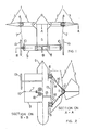
- the ornithopter illustrated has each of its wings (1) made-up in two segments (2) and (3) connected by a yawing hinge (4) whose axis is generally perpendicular to the plane of the inboard wing segment (2).
- the outboard wing segment (3) can be yawed relative to the inboard wing segment (2) about the axis of hinge (4).
- the inboard wing segment (2) is connected to the fuselage (5) via a flapping hinge (6) whose axis lies generally parallel to the longitudinal axis of the fuselage (5).
- the inboard wing segment (2) is spring-restrained in the flapping direction by a cable (7) and spring (8) located in an auxiliary streamlined strut (9).
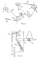
- An idler pulley (10) is provided to allow the restraining cable (7) to operate freely. Forward or rearward yawing movement of the outboard wing segment (3) relative to the inboard wing segment (2) is effected through the arrangement of sprocket wheel (11), chain (12), cable (13), idler pulleys (14) and input-power/ control stick (15) by the action of pulling back or pushing forward the stick (15), respectively.
- a spring (16) keeps the chain (12) taught at all times and a guide (17) retains the stick (15) in proper alignment with cable (13) and idler pulleys (14).
- the restraining-spring-pack (8) is made-up of a number of constant load springs (18) clustered together to guard against catastrophic failure that might be occasioned by the use of a single spring.
- the constant load springs (18) offer the desirable feature of compactness, a nearly constant step load and a large working deflection.
- the ornithopter In operational use the ornithopter is foot launched, towed or driven via pedalled or powered wheels (19) into the oncoming wind.
- the stick (15) When a suitable speed is reached the stick (15) is pulled back swiftly. This action causes the outboard wing segment (3) to be flicked forward in a yawing motion generating impulsive lift in the process: If the resulting impulsive torque is sufficiently high it would force the whole wing upwards against the pull of the restraining cable (7) and spring (8).
- the excess lift is lost and the process reverses, i.e. the wing is pulled downwards by the spring (8).
- the outboard wing segment (3) At the bottom of the downstroke the outboard wing segment (3) is swept rearwards, by pushing the stick (15) forward, to generate additional thrust and to prepare the wing for its next beat.
- Control of the ornithopter is available through the stick (15) longitudinally by a symmetrical for- ward/rearward movement of the stick and laterally by an antisymmetrical, yawing, movement of the stick (15) as indicated by the broad arrows in Figure 5.
- the restraining-spring-pack unit (8) is located inside the fuselage (5) with the optional single wheel (19) partially concealed in said fuselage to reduce aerodynamic drag. Buffeting, if a problem, may be damped by the installation of a shock absorber unit (20).
Landscapes
- Engineering & Computer Science (AREA)
- Aviation & Aerospace Engineering (AREA)
- Toys (AREA)
- Aerodynamic Tests, Hydrodynamic Tests, Wind Tunnels, And Water Tanks (AREA)
Claims (2)
Priority Applications (1)
| Application Number | Priority Date | Filing Date | Title |
|---|---|---|---|
| AT83104220T ATE30887T1 (de) | 1982-07-02 | 1983-04-29 | Fluegelschlagen mit aerodynamischer induktion fuer die triebkraft eines schwingenflugzeuges. |
Applications Claiming Priority (2)
| Application Number | Priority Date | Filing Date | Title |
|---|---|---|---|
| CA000406479A CA1183509A (en) | 1982-07-02 | 1982-07-02 | Aerodynamically-induced wing-flapping for the propulsion of ornithopters |
| CA406479 | 1982-07-02 |
Publications (3)
| Publication Number | Publication Date |
|---|---|
| EP0098355A2 EP0098355A2 (de) | 1984-01-18 |
| EP0098355A3 EP0098355A3 (en) | 1984-11-14 |
| EP0098355B1 true EP0098355B1 (de) | 1987-11-19 |
Family
ID=4123141
Family Applications (1)
| Application Number | Title | Priority Date | Filing Date |
|---|---|---|---|
| EP83104220A Expired EP0098355B1 (de) | 1982-07-02 | 1983-04-29 | Flügelschlagen mit aerodynamischer Induktion für die Triebkraft eines Schwingenflugzeuges |
Country Status (6)
| Country | Link |
|---|---|
| EP (1) | EP0098355B1 (de) |
| AT (1) | ATE30887T1 (de) |
| AU (1) | AU554906B2 (de) |
| CA (1) | CA1183509A (de) |
| DE (1) | DE3374544D1 (de) |
| WO (1) | WO1984000136A1 (de) |
Families Citing this family (5)
| Publication number | Priority date | Publication date | Assignee | Title |
|---|---|---|---|---|
| GB2144089B (en) * | 1983-07-26 | 1986-07-23 | George Allan Essex | Improvements in flying machines |
| GB2201931B (en) * | 1987-01-07 | 1990-12-19 | William Thoby Fisher | Flapping-wing aircraft |
| AT399322B (de) * | 1993-01-15 | 1995-04-25 | Seewald Franz Ing | Schwingenflugzeug mit muskelkraftantrieb |
| GB2504369B (en) * | 2013-03-05 | 2014-06-25 | Cvr Ltd | Aircraft wing |
| CN119734837B (zh) * | 2025-03-06 | 2025-05-27 | 吉林大学 | 一种线绳传动扑动机构的仿生蜻蜓扑翼飞行器 |
Family Cites Families (7)
| Publication number | Priority date | Publication date | Assignee | Title |
|---|---|---|---|---|
| DE1050664B (de) * | 1959-02-12 | |||
| FR430647A (fr) * | 1911-06-07 | 1911-10-20 | Louis Joseph Jean Baptiste Che | Perfectionnements apportés aux engins de navigation aérienne, également applicables, entre autres objets, aux engins de navigation aquatique |
| US1783029A (en) * | 1927-10-31 | 1930-11-25 | George R White | Ornithopter |
| US2061075A (en) * | 1934-11-03 | 1936-11-17 | Jelalian Martin | Airship |
| US2359264A (en) * | 1942-02-11 | 1944-09-26 | Benjamins Israel | Aircraft |
| FR1228320A (fr) * | 1959-03-12 | 1960-08-29 | Voilure sustento-propulsive | |
| US4139171A (en) * | 1976-07-16 | 1979-02-13 | Harris Jeremy M | Articulated wing ornithopter |
-
1982
- 1982-07-02 CA CA000406479A patent/CA1183509A/en not_active Expired
-
1983
- 1983-04-28 AU AU17061/83A patent/AU554906B2/en not_active Ceased
- 1983-04-28 WO PCT/US1983/000618 patent/WO1984000136A1/en not_active Ceased
- 1983-04-29 DE DE8383104220T patent/DE3374544D1/de not_active Expired
- 1983-04-29 AT AT83104220T patent/ATE30887T1/de not_active IP Right Cessation
- 1983-04-29 EP EP83104220A patent/EP0098355B1/de not_active Expired
Also Published As
| Publication number | Publication date |
|---|---|
| CA1183509A (en) | 1985-03-05 |
| EP0098355A3 (en) | 1984-11-14 |
| AU1706183A (en) | 1984-01-26 |
| WO1984000136A1 (en) | 1984-01-19 |
| AU554906B2 (en) | 1986-09-04 |
| ATE30887T1 (de) | 1987-12-15 |
| EP0098355A2 (de) | 1984-01-18 |
| DE3374544D1 (en) | 1987-12-23 |
Similar Documents
| Publication | Publication Date | Title |
|---|---|---|
| US6802473B2 (en) | Ornithopter with flexible fuselage | |
| US3807662A (en) | Anti-torque, propulsion, and directional control system | |
| US6250585B1 (en) | Impellers with bladelike elements and compliant tuned transmission shafts and vehicles including same | |
| US5072894A (en) | Apparatus and method for increasing the angle of attack operating range of an aircraft | |
| EP0461296A1 (de) | Schlitze für die regelbare Zirkulation bei einer Hubschrauberseitensteuerung | |
| US5899408A (en) | Ornithopter | |
| EP0098355B1 (de) | Flügelschlagen mit aerodynamischer Induktion für die Triebkraft eines Schwingenflugzeuges | |
| JP5490717B2 (ja) | 羽ばたき翼を有する筋力駆動飛行機 | |
| CN110294119A (zh) | 翼片自适应转动摆动式变倾角扑翼装置及扑翼方法 | |
| JP5207458B2 (ja) | 羽ばたき飛行機 | |
| US3410506A (en) | Extensible rotor airplane | |
| US20160052619A1 (en) | Simplified inverted v-tail stabilizer for aircraft | |
| US2793826A (en) | Split aircraft wing | |
| JP2005119658A (ja) | 羽ばたき飛行機および羽ばたき飛行方法 | |
| US3008671A (en) | Main rotor and pylon fairing | |
| GB2201931A (en) | Ornithopters | |
| RU2009072C1 (ru) | Дирижабль | |
| US1910098A (en) | Airplane | |
| US1760386A (en) | Flying machine | |
| RU2083437C1 (ru) | Летательный аппарат "стрекоза" | |
| US1394816A (en) | Flying-machine | |
| US1096045A (en) | Flying-machine. | |
| US3458162A (en) | Control devices for flexible wing aircraft | |
| US11053001B2 (en) | Low-drag fairing and rotor assembly | |
| US1737963A (en) | Flying machine |
Legal Events
| Date | Code | Title | Description |
|---|---|---|---|
| PUAI | Public reference made under article 153(3) epc to a published international application that has entered the european phase |
Free format text: ORIGINAL CODE: 0009012 |
|
| 17P | Request for examination filed |
Effective date: 19830429 |
|
| AK | Designated contracting states |
Designated state(s): AT CH DE FR GB IT LI NL SE |
|
| PUAL | Search report despatched |
Free format text: ORIGINAL CODE: 0009013 |
|
| AK | Designated contracting states |
Designated state(s): AT CH DE FR GB IT LI NL SE |
|
| GRAA | (expected) grant |
Free format text: ORIGINAL CODE: 0009210 |
|
| AK | Designated contracting states |
Kind code of ref document: B1 Designated state(s): AT CH DE FR GB IT LI NL SE |
|
| PG25 | Lapsed in a contracting state [announced via postgrant information from national office to epo] |
Ref country code: IT Free format text: LAPSE BECAUSE OF FAILURE TO SUBMIT A TRANSLATION OF THE DESCRIPTION OR TO PAY THE FEE WITHIN THE PRESCRIBED TIME-LIMIT;WARNING: LAPSES OF ITALIAN PATENTS WITH EFFECTIVE DATE BEFORE 2007 MAY HAVE OCCURRED AT ANY TIME BEFORE 2007. THE CORRECT EFFECTIVE DATE MAY BE DIFFERENT FROM THE ONE RECORDED. Effective date: 19871119 Ref country code: AT Effective date: 19871119 |
|
| REF | Corresponds to: |
Ref document number: 30887 Country of ref document: AT Date of ref document: 19871215 Kind code of ref document: T |
|
| REF | Corresponds to: |
Ref document number: 3374544 Country of ref document: DE Date of ref document: 19871223 |
|
| ET | Fr: translation filed | ||
| PLBE | No opposition filed within time limit |
Free format text: ORIGINAL CODE: 0009261 |
|
| STAA | Information on the status of an ep patent application or granted ep patent |
Free format text: STATUS: NO OPPOSITION FILED WITHIN TIME LIMIT |
|
| 26N | No opposition filed | ||
| PG25 | Lapsed in a contracting state [announced via postgrant information from national office to epo] |
Ref country code: GB Effective date: 19890429 |
|
| PG25 | Lapsed in a contracting state [announced via postgrant information from national office to epo] |
Ref country code: SE Effective date: 19890430 Ref country code: LI Effective date: 19890430 Ref country code: CH Effective date: 19890430 |
|
| PG25 | Lapsed in a contracting state [announced via postgrant information from national office to epo] |
Ref country code: NL Effective date: 19891101 |
|
| NLV4 | Nl: lapsed or anulled due to non-payment of the annual fee | ||
| GBPC | Gb: european patent ceased through non-payment of renewal fee | ||
| PG25 | Lapsed in a contracting state [announced via postgrant information from national office to epo] |
Ref country code: FR Free format text: LAPSE BECAUSE OF NON-PAYMENT OF DUE FEES Effective date: 19891228 |
|
| REG | Reference to a national code |
Ref country code: CH Ref legal event code: PL |
|
| PG25 | Lapsed in a contracting state [announced via postgrant information from national office to epo] |
Ref country code: DE Effective date: 19900103 |
|
| REG | Reference to a national code |
Ref country code: FR Ref legal event code: ST |
|
| EUG | Se: european patent has lapsed |
Ref document number: 83104220.5 Effective date: 19900412 |