EP0098458A2 - Appareil d'ancrage pour une ceinture de siège - Google Patents
Appareil d'ancrage pour une ceinture de siège Download PDFInfo
- Publication number
- EP0098458A2 EP0098458A2 EP83106081A EP83106081A EP0098458A2 EP 0098458 A2 EP0098458 A2 EP 0098458A2 EP 83106081 A EP83106081 A EP 83106081A EP 83106081 A EP83106081 A EP 83106081A EP 0098458 A2 EP0098458 A2 EP 0098458A2
- Authority
- EP
- European Patent Office
- Prior art keywords
- lever
- seat
- track
- vehicle
- cable
- Prior art date
- Legal status (The legal status is an assumption and is not a legal conclusion. Google has not performed a legal analysis and makes no representation as to the accuracy of the status listed.)
- Granted
Links
- 238000004873 anchoring Methods 0.000 title claims description 13
- 230000007246 mechanism Effects 0.000 claims abstract description 36
- 229910000831 Steel Inorganic materials 0.000 claims description 3
- 239000010959 steel Substances 0.000 claims description 3
- 230000000452 restraining effect Effects 0.000 claims description 2
- 230000000750 progressive effect Effects 0.000 claims 1
- 230000003068 static effect Effects 0.000 description 5
- 230000000694 effects Effects 0.000 description 3
- 239000002184 metal Substances 0.000 description 2
- 239000004677 Nylon Substances 0.000 description 1
- 238000010276 construction Methods 0.000 description 1
- 230000000994 depressogenic effect Effects 0.000 description 1
- 230000013011 mating Effects 0.000 description 1
- 229920001778 nylon Polymers 0.000 description 1
- 230000000284 resting effect Effects 0.000 description 1
- 238000010008 shearing Methods 0.000 description 1
- 230000035939 shock Effects 0.000 description 1
- 239000007787 solid Substances 0.000 description 1
Images

Classifications
-
- B—PERFORMING OPERATIONS; TRANSPORTING
- B60—VEHICLES IN GENERAL
- B60R—VEHICLES, VEHICLE FITTINGS, OR VEHICLE PARTS, NOT OTHERWISE PROVIDED FOR
- B60R22/00—Safety belts or body harnesses in vehicles
- B60R22/18—Anchoring devices
- B60R22/26—Anchoring devices secured to the seat
Definitions
- Seat belts for a motor vehicle are generally directly anchored to the floor or window pillars of the vehicle body to produce the requisite strength to resist collision forces.
- seat track mechanisms are employed to provide horizontal and/or vertical adjustment for the seat, the seat belts are still anchored directly to the vehicle body since the adjustment mechanism is not engineered to withstand collision or crash loading forces which include from the weight of the seat occupant.
- Patents have issued showing apparatus for anchoring seat belts to the seat tracks, for example, U.S. Patent 3,186,760 to T. Lohr et al issued June 1, 1965; 4,225,184 to Strowick issued September 30, 1980; 4,229,041 issued October 21, 1980 to P. Werner and 4,260,178 issued April 7, 1981. These structures generally function to force a seat member into engagement with the vehicle floor on the application of crash level forces on the seat belt.
- seat belt locating mechanisms such as U.S. Patent 3,424,494 issued January 28, 1969 to McIntyre et al, i.e. which the seat belt is depressed to release the engagement of a pin in recess between the belt and seat track mount. The belt may be moved to a desired location in which the engagement is restored.
- the present invention is directed to apparatus which allows the seat belt mount to move with the vehicle seat track mechanism on normal adjustment of the seat track mechanism and acts to clamp the seat belt mount to the vehicle body in case of a crash.
- the present solution to this known problem is accomplished with but little added weight.
- the present invention meets the crash loading specifications of five to six thousand pounds of force applied to the seat belt without separating the seat structure from the vehicle.
- the present invention is equally applicable to seat track mechanisms of the manual type and to those of the powered or motor driven type.
- a lower track which is secured to the vehicle body or floor.
- the upper track is slidable along the lower track and is held in a position once adjusted to that position.
- the relative position in generally held by a tooth in socket engagement while in the powered type, the engagement is held within the driving members such as a screw in a nut.
- the adjustment holding is generally sufficient to retain the seat in place under normal conditions and to retain the seat and track alone under crash conditions.
- the seat adjusting mechanism is not of sufficient strength to retain the hold engagement under collision or crash loads.
- the seat belt is mounted pivotally to the upper seat track for fore and aft movement with the seat. During normal conditions, adjustment of the seat track is unencumbered by the normally disengaged clamp apparatus.
- the clamp apparatus includes the pivotal lever commoaly mounted with a clamp receiver on the upper seat track.
- a wire cable is affixed to the vehicle floor or to the lower track, forward and aft of the lever.
- the cable preferably is held reasonably taut between its cable mounts.
- the cable receiver or clamp bracket straddles the wire cable and is secured to the upper track by the pivot mount for the lever.
- the free end of the lever serves as the end mount for the seat belt.
- the seat belt mount lever or clamp lever is held in its disengaged condition by a hold means.
- the hold means may be a spring or may be a shear pin normally obstructing rotation of the lever.
- the spring releases the lever for movement or the pin shears to allow the lever to rotate to an anchor position clamping the cable against the cable receiver clamp to prevent relative motion between the upper track of the mechanism and the lower track and vehicle body or floor.
- the present apparatus is most applicable to split type seats in which there is a track at each side of the belt area for a user such that either one or preferably both belt ends can be secured in the manner shown for the one side herein.
- central slave tracks could be positioned intermediate the seat width to anchor the inboard ends of the seat belts.
- the clamping cam is released for rotation at a nominal value of seat belt pull such as 400 lbs.
- seat belt pull such as 400 lbs.
- the cam begins to rotate and clamp against the cable.
- the seat track absorbs the force of the pull.
- the cam lever has rotated through an angular extent sufficient to clamp the cable frictionally.
- the clamp action of cam to cable will lock the seat belt to the floor anchor. In this way, a static frictional gripping force from cam to cable is generated to enable the seat belt to withstand a pull force of up to 6000 pounds.
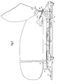
- a seat track mechanism 12 which may be a manual seat track or may be a seat track whose adjustment is power driven. Specifically shown is the structure of a power driven track such as that of U.S. patent 4,015,812 issued April 5, 1977 to M. O. Heesch. The structure shown forms one side of the full seat track mechanism, the other side of the mechanism being the mirror image of that shown.
- the track mechanism 12 as is conventional is comprised of a stationary lower track 14 in which there is mounted an upper slidable track 16.
- the lower track 14 is secured by rivets or the like to mounting brackets 20 both at front and rear. By any conventional means such as bolts 22, the brackets 20 may be fixed to the vehicle floor 23.
- the lower track is U shaped with outwardly extending flanges 24 (Fig. 2) to which are affixed conventional sliding blocks 26 of nylon or the like.
- the upper track comprises a downwardly open channel with inwardly directed lower flanges 30 straddling blocks 26 within the flanges to enable translatory sliding motion of the respective upper tracks on the stationary lower tracks.
- Track mechanisms are provided at each lateral side of the seat, the track mechanism being elongated longitudinally as is conventional.
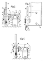
- a U shaped steel clamp bracket 40 with a mounting cross bar 42 stepped from the body 44 of the bracket U is fastened securely to the upper track by suitable fastening means such as spaced rivets 46.
- the riveting provides a connection which will withstand heavy shock loading forces.
- the U body of bracket 40 extends alongside the lower track and is parallel to the track as seen best in Figs. 2 and 3.
- the base of the U body is convex with a crowned section or arcuate crest 50 at the longitudinal center of the body with the base curved downwardly at the longitudinal ends 51 (as seen best in Figs. 1).
- the parallel legs of the clamp bracket body have aligned circular bearing openings in which pivot rod 52 is mounted.
- the rod 52 has an enlarged head 54 outside one leg 50 of the body 44 from which a rod mid-section protrudes through the legs of the U.body to its free end adjacent the upper track.
- a retainer such as a C-shaped snap ring 58 is fitted in a suitable groove adjacent the end of the rod acts to hold the rod in place on the bracket 40.
- a cotter pin (not shown) may be inserted through a suitable opening in the rod.
- a lever 60 is mounted on the pivot rod, the lever being rotatable in the space between the legs of the U body 44.
- the upper end 62 of the lever 60 serves as mount for the seat belt (not shown).
- the lower end of the lever 60 is configured with an arcuate cam face 64 of gradually increasing diameter (see Fig. 1) in the forward direction terminating in a ramp 66.
- the cam face is spaced a distance from the crowned section 50 of bracket 40 at any angular orientation of the cam face 64.
- the portion of the face 62 adjacent ramp 66 of course, would be the closest to the crown with the cam face in a position shown in dashed lines in Fig. 1.
- the cable 70 extends longitudinally parallel to the seat track at a height just above the crowned section.
- the cable 70 preferably may be steel aircraft cable of a type known for superior strength in tension and shear, and having a nominal outer diameter of u. 635 em. Such a cable has a minimum break strength of 2676 kg.
- the cable is gripped by means of a conventional swage fitting 74, over the cable, the swage fitting having an eye for securement to the vehicle floor in a structural solid manner.
- the cable extends substantially taut alongside the track mechanism for a distance greater than the maximum travel of the track mechanism, which may range from 12 cm to 23 cm, the cable allowing the full travel of the track without bracket 40 striking either of the cable end fittings 74.
- a cable having an outer diameter of from 0.56 too.8cm may be used satisfactorily. Cable has been found to be preferable over a metal rod, rigid metal block, beam or bar due to other considerations such as ease of mounting and alignment. Since, however, tensile strength of the cable or rod is the major property necessary, a bar, rod or beam could be used. Aesthetically, the front anchor of the cable may be hidden beneath the floor carpet with the cable resting in a carpet slit.
- the seat belt terminating lever 60 moves with the seat.
- no resetting of the belt becomes necessary when the seat is adjusted after the belt has been tightened on the body of the seat occupant.
- the lever and seat belt are held in the position shown in full lines in Fig. 1 by a spring such as the tension spring 80 which is secured suitably to a rearward extension 82 of the horizontal mounting section of the U clamp bracket.
- the spring resists forces on the belt tending to move the lever.
- the cam face 64 With the lever in the solid line poisition, the cam face 64 is free of engagement with the cable 70 and the cable is spaced free of the crown 50 of the U clamp body 44: Movement of the seat track is unimpeded by the anchoring apparatus shown.
- Spring 80 will elongate when a predetermined pulling force is applied to the lever 60 by the belt, a force of more than the 18 0 kg being required to move the lever from the solid line position of Fig. L
- the clamp bracket With the full clamp action in. force, the clamp bracket tends to deflect in a counter clockwise direction (as viewed in Fig. 2) about its mounting at rivets to bind the clamp bracket and lever to the cable. In this way the upper track and seat borne thereby are firmly anchored to the vehicle floor and structure during the collision condition.
- the anchoring becomes independent of the latching or mating of the upper track to the lower track after sufficient rotation of the cam to generate the static frictional gripping force between lever, bracket and cable.
- the arcuate crown prevents the cable from being sheared by the lever compressing the cable against the clamp bracket.
- the increase in radius of the lever cam face 64 in the direction of rotation of the lever provides an excursion equal to almost the full diameter of the cable 70.
- the force applied on the lever when plotted provides a curve indicative of greater force per cam excursion than a straight line function.
- cam rotation values of less than 20 the friction between cam and cable is essentially a straight line function due to sliding friction. In this range, the seat position is held by the seat track latch action.
- the amount of rotation of the cam lessens.
- the clamping action is generated by the static friction between cam, cable and clamp bracket.
- Figs. 4 and 5 differs from that of Figs. 1-3 in a number of areas; i.e. the forward mounting of the cable, the means for maintaining the lever in the normal position (spring 80 in Figs. 1-3) and the use of an insert to provide the crown in the clamp bracket.
- the front end of the cable 70 is held within a suitable cable end swage fitting 90, the fitting being held by an L shaped bracket -92 affixed to the underside of the lower track 14 by suitable rivets.
- the mounting of the cable fitting to the floor may be difficult to perform.
- mounting of the cable front end to the stationary lower track as shown by Figs. 4 and 5, should be easier to implement.
- the lower seat track 14 is fixed to the vehicle floor 23 so the net effect is the same as that for the mounting of Figs. 1-3 in strength.
- a second point of difference in the embodiment of Figs. 4 and 5 is the replacement of the spring 80 with a shear pin 94.
- the shear pin which may be a cotter pin, as shown, extends through the aligned opening 96 legs of the clamp bracket and through an aligned opening 98 in the lever arm.
- shear pin may be external to and abut the edge of the lever 60' without the need for an opening in the lever.
- a suitable backstop would also be provided to position the lever, the backstop preferably being a bent over tab on the clamp bracket.
- the lever will cause the pin 94 to shear and allow the lever 60' to pivot toward the clamping positions.
- the value of shear force has been chosen as one sufficiently high to prevent clamp action and interference with seat track movement under the normal operating conditions of the vehicle.
- the pin 94 will shear as the forces increase above the normal toward the collision forces.
- the specification mandated by the Federal government require that the seat belt withstand forces of up to 2720 kg and clamping mechanisms of the type shown in either embodiment herein have been found to meet those requirements.
- the final point of difference in the embodiment of Figs. 4 and 5 is the use of a crown insert 50' within the clamp bracket.
- the insert is an arcuate convex headed member symmetrical relative to the vertical plane through the pivot pin of Fig. 4.
- the crown insert 50' has overhang members 95 crimped or snap fitted about the edges of the clamp bracket to hold it firmly in place.
- the pin 94 must be replaced once it has been sheared. For this reason, the shear value of the pin must be sufficiently high to prevent shearing of the pin under sharp braking condition and other normally encountered conditions. The pin will however, shear sufficiently below the actual crash loading to enable the clamp action without impediment.
- the value of pull at which the spring of Figs. 1-3 and the shear pin of Figs. 4-5 allow appreciable movement of the cam lever has been chosen as approximately 18 0 kg. This value was selected as the weight of aninety kilogram person being moved with a force of 2g's.
- This restraint can be set at any desired level by the selection of spring or shear pin characteristics. The level selected is one which will not allow cam movement during normal driving and braking conditions even with minor panic stops including collisions up to B km/h (5 m.p.h.).
- the resistance of the seat track mechanism to crash loads is one which is required by federal standards.
- the track mechanism whether manual or powered must withstand forces of up to 6 30 kg - collision force without seat occupant. When the weight of a seat occupant is added, the forces are above those required of the seat track mechanism itself.
- Such mechanisms are, of course, common in the automotive industry and are shown by numerous patents.
- a seat belt anchor using static frictional braking, and during the period in which the sliding friction is being generated, the secondary restraining force of the track mechanism is employed.
- the applied force is sufficiently great to cause the pivotal clamping cam to compress the cable against the clamp receiver with a static friction force during the period when the seat track mechanism restraint is active.
- the clamping action of the present invention anchors the seat belt and seat track to the vehicle body for pulling force values well above the required levels.
Landscapes
- Engineering & Computer Science (AREA)
- Mechanical Engineering (AREA)
- Seats For Vehicles (AREA)
- Automotive Seat Belt Assembly (AREA)
Applications Claiming Priority (2)
| Application Number | Priority Date | Filing Date | Title |
|---|---|---|---|
| US394680 | 1982-07-02 | ||
| US06/394,680 US4488754A (en) | 1982-07-02 | 1982-07-02 | Seat belt anchoring apparatus |
Publications (3)
| Publication Number | Publication Date |
|---|---|
| EP0098458A2 true EP0098458A2 (fr) | 1984-01-18 |
| EP0098458A3 EP0098458A3 (en) | 1987-05-06 |
| EP0098458B1 EP0098458B1 (fr) | 1990-08-08 |
Family
ID=23559974
Family Applications (1)
| Application Number | Title | Priority Date | Filing Date |
|---|---|---|---|
| EP83106081A Expired - Lifetime EP0098458B1 (fr) | 1982-07-02 | 1983-06-22 | Appareil d'ancrage pour une ceinture de siège |
Country Status (4)
| Country | Link |
|---|---|
| US (1) | US4488754A (fr) |
| EP (1) | EP0098458B1 (fr) |
| JP (1) | JPS5914549A (fr) |
| DE (1) | DE3381792D1 (fr) |
Cited By (5)
| Publication number | Priority date | Publication date | Assignee | Title |
|---|---|---|---|---|
| GB2183988A (en) * | 1985-12-11 | 1987-06-17 | Avtomobilny Z Im Leninskogo Ko | Device for attaching a safety belt to a vehicle seat |
| FR2595300A1 (fr) * | 1986-03-06 | 1987-09-11 | Peugeot | Siege transformable de vehicule automobile, equipe d'un dispositif d'accrochage pour ceinture de securite |
| AT394005B (de) * | 1988-04-29 | 1992-01-27 | Austria Metall | Gurtwiderlager an fahrzeugsitzen |
| EP0716963A1 (fr) | 1994-12-16 | 1996-06-19 | FIAT AUTO S.p.A. | Dispositif d'ancrage d'une extrémité de ceinture de sécurité de véhicule automobile |
| CN119714829A (zh) * | 2024-11-27 | 2025-03-28 | 东风汽车集团股份有限公司 | 一种安全带固定点强度验证定位装置及方法 |
Families Citing this family (18)
| Publication number | Priority date | Publication date | Assignee | Title |
|---|---|---|---|---|
| JPH0439084Y2 (fr) * | 1985-12-09 | 1992-09-11 | ||
| JPH0537883Y2 (fr) * | 1987-03-03 | 1993-09-24 | ||
| JPH088243B2 (ja) * | 1989-12-13 | 1996-01-29 | 三菱電機株式会社 | 表面クリーニング装置及びその方法 |
| US5087009A (en) * | 1990-11-28 | 1992-02-11 | General Motors Corporation | Power seat adjuster with integral horizontal interlock system |
| US5320308A (en) * | 1991-12-04 | 1994-06-14 | Weber Aircraft, Inc. | Seatback breakover device |
| US5219206A (en) * | 1992-01-22 | 1993-06-15 | Indiana Mills & Manufacturing, Inc. | Automatic locking tether for vehicle seat |
| US5219207A (en) * | 1992-01-22 | 1993-06-15 | Indiana Mills & Manufacturing, Inc. | Automatic locking tether for vehicle seat |
| US5295729A (en) * | 1992-02-18 | 1994-03-22 | General Motors Corporation | High retention seat back |
| US5366268A (en) * | 1993-10-04 | 1994-11-22 | General Motors Corporation | High strength seat back |
| TW269743B (fr) * | 1994-04-26 | 1996-02-01 | Toshiba Eng Co | |
| US5462332A (en) * | 1994-10-03 | 1995-10-31 | General Motors Corporation | High strength vehicle recliner seat |
| US5642916A (en) * | 1995-08-22 | 1997-07-01 | Alliedsignal Inc. | Locking and tensioning for a slidable seat |
| FR2759331B1 (fr) * | 1997-02-13 | 1999-04-30 | Ecia Equip Composants Ind Auto | Agencement d'un siege, notamment une banquette arriere, dans un habitacle de vehicule automobile |
| JP2001091347A (ja) * | 1999-09-24 | 2001-04-06 | Aisin Seiki Co Ltd | 着座荷重検出装置 |
| FR2875187B1 (fr) * | 2004-09-10 | 2008-03-14 | Faurecia Sieges Automobile | Siege de vehicule automobile comportant une assise reglable en hauteur et un point d'attache d'une ceinture de securite lie a l'assise |
| JP2010162951A (ja) * | 2009-01-13 | 2010-07-29 | Aisin Seiki Co Ltd | 車両用シート装置 |
| JP5395457B2 (ja) * | 2009-02-25 | 2014-01-22 | テイ・エス テック株式会社 | 車両用シート |
| JP5559892B2 (ja) * | 2010-11-22 | 2014-07-23 | ジョンソン コントロールズ テクノロジー カンパニー | 乗り物用シート |
Family Cites Families (18)
| Publication number | Priority date | Publication date | Assignee | Title |
|---|---|---|---|---|
| US496958A (en) * | 1893-05-09 | Fire-escape | ||
| US564012A (en) * | 1896-07-14 | Tackle-block | ||
| US1368650A (en) * | 1919-10-27 | 1921-02-15 | William H Ortman | Clothesline-support |
| US2662734A (en) * | 1952-06-13 | 1953-12-15 | Wilberd F Feigenbaum | Swing stage scaffold |
| US3186760A (en) * | 1963-05-24 | 1965-06-01 | Gen Motors Corp | Combination seat belt anchoring and seat braking mechanism |
| JPS5332128B2 (fr) * | 1971-09-18 | 1978-09-06 | ||
| US3897101A (en) * | 1973-05-18 | 1975-07-29 | Brose & Co Metallwerk Max | Driver{3 s seat with inertia-responsive locking arrangement |
| DE2349829C2 (de) * | 1973-10-04 | 1982-12-30 | Daimler-Benz Ag, 7000 Stuttgart | Rückhaltevorrichtung für die Insassen von Fahrzeugen |
| JPS5411431U (fr) * | 1977-06-27 | 1979-01-25 | ||
| DE2742668C2 (de) * | 1977-09-22 | 1982-11-18 | Adam Opel AG, 6090 Rüsselsheim | Sicherheitsgurtbefestigung |
| JPS5459722A (en) * | 1977-10-18 | 1979-05-14 | Toyota Motor Corp | Seat belt device |
| DE2802617C2 (de) * | 1978-01-21 | 1985-01-10 | Keiper Automobiltechnik Gmbh & Co Kg, 5630 Remscheid | Verankerung für Gurtschlösser |
| DE2802616C2 (de) * | 1978-01-21 | 1982-06-09 | Keiper Automobiltechnik Gmbh & Co Kg, 5630 Remscheid | Verankerung für Gurtschlösser von in Fahrzeugen angeordneten Sicherheitsgurten |
| DE2803896A1 (de) * | 1978-01-30 | 1979-08-02 | Keiper Automobiltechnik Gmbh | Verankerung fuer gurtschloesser von in fahrzeugen angeordneten sicherheitsgurten |
| DE2826634A1 (de) * | 1978-06-19 | 1980-01-03 | Daimler Benz Ag | An einem festen fahrzeugteil sich abstuetzende rastschiene |
| DE7836672U1 (de) * | 1978-12-11 | 1980-10-09 | Adam Opel Ag, 6090 Ruesselsheim | Vorrichtung zur befestigung eines sicherheitsgurtes an einem kraftfahrzeugsitz |
| JPS5914293Y2 (ja) * | 1979-09-10 | 1984-04-26 | トヨタ自動車株式会社 | シ−トベルトアンカ−装置 |
| US4349216A (en) * | 1980-09-22 | 1982-09-14 | The Firestone Tire & Rubber Company | Floating lock mount for a seat belt retractor |
-
1982
- 1982-07-02 US US06/394,680 patent/US4488754A/en not_active Expired - Fee Related
-
1983
- 1983-06-22 EP EP83106081A patent/EP0098458B1/fr not_active Expired - Lifetime
- 1983-06-22 DE DE8383106081T patent/DE3381792D1/de not_active Expired - Lifetime
- 1983-06-30 JP JP58117178A patent/JPS5914549A/ja active Granted
Cited By (6)
| Publication number | Priority date | Publication date | Assignee | Title |
|---|---|---|---|---|
| GB2183988A (en) * | 1985-12-11 | 1987-06-17 | Avtomobilny Z Im Leninskogo Ko | Device for attaching a safety belt to a vehicle seat |
| GB2183988B (en) * | 1985-12-11 | 1989-10-11 | Avtomobilny Z Im Leninskogo Ko | Device for attaching a safety belt to a vehicle seat |
| FR2595300A1 (fr) * | 1986-03-06 | 1987-09-11 | Peugeot | Siege transformable de vehicule automobile, equipe d'un dispositif d'accrochage pour ceinture de securite |
| AT394005B (de) * | 1988-04-29 | 1992-01-27 | Austria Metall | Gurtwiderlager an fahrzeugsitzen |
| EP0716963A1 (fr) | 1994-12-16 | 1996-06-19 | FIAT AUTO S.p.A. | Dispositif d'ancrage d'une extrémité de ceinture de sécurité de véhicule automobile |
| CN119714829A (zh) * | 2024-11-27 | 2025-03-28 | 东风汽车集团股份有限公司 | 一种安全带固定点强度验证定位装置及方法 |
Also Published As
| Publication number | Publication date |
|---|---|
| EP0098458A3 (en) | 1987-05-06 |
| EP0098458B1 (fr) | 1990-08-08 |
| DE3381792D1 (de) | 1990-09-13 |
| JPH0356211B2 (fr) | 1991-08-27 |
| US4488754A (en) | 1984-12-18 |
| JPS5914549A (ja) | 1984-01-25 |
Similar Documents
| Publication | Publication Date | Title |
|---|---|---|
| US4488754A (en) | Seat belt anchoring apparatus | |
| US6352312B1 (en) | Vehicle seat interlock | |
| US5213300A (en) | Extruded automotive seat track | |
| US3957304A (en) | Restraint for a vehicle seat and seat belt | |
| US6921136B2 (en) | Automatic seat belt buckle tongue releasing mechanism | |
| US4832409A (en) | Restraint belt load capacity fore and aft power seat adjuster apparatus | |
| JPH0775949B2 (ja) | 長手方向ガイドと高さ又は傾斜変位部とベルトロック固定部とを備えた自動車用シート | |
| US5316258A (en) | Power seat adjuster with drive gear force bypass | |
| JPH11255011A (ja) | 自動車のシートのシートパン | |
| US4349216A (en) | Floating lock mount for a seat belt retractor | |
| US5895090A (en) | Vehicle with integrated restraint system | |
| US4813645A (en) | Vehicle seat with suspension device | |
| EP0638028B1 (fr) | Support de montage rotatif d'une boucle de ceinture de securite pour un dispositif de reglage de siege de vehicule | |
| US6478334B1 (en) | Energy-absorbing anchor, D-ring, turning loop or web guide | |
| US4944531A (en) | Device for coupling a bracket which is provided with a buckle of a seat belt, to a retaining member, which is fixed in a vehicle | |
| US5499788A (en) | Manual seat adjuster | |
| US7360795B2 (en) | Torsion bar load limiter and pretensioner for seat belt system | |
| EP0696250B1 (fr) | Dispositif de reglage de siege de vehicule | |
| EP0942843A1 (fr) | Ameliorations portant sur un siege pour vehicules | |
| GB2183988A (en) | Device for attaching a safety belt to a vehicle seat | |
| US5924773A (en) | Safety belt fastening arrangement | |
| EP0928256B1 (fr) | Ensemble de siège de véhicule comportant des ceintures de sécurité | |
| JPH036013B2 (fr) | ||
| GB2339145A (en) | A vehicle seat |
Legal Events
| Date | Code | Title | Description |
|---|---|---|---|
| PUAI | Public reference made under article 153(3) epc to a published international application that has entered the european phase |
Free format text: ORIGINAL CODE: 0009012 |
|
| 17P | Request for examination filed |
Effective date: 19830622 |
|
| AK | Designated contracting states |
Designated state(s): DE GB IT SE |
|
| RAP1 | Party data changed (applicant data changed or rights of an application transferred) |
Owner name: ITT INDUSTRIES INC. |
|
| PUAL | Search report despatched |
Free format text: ORIGINAL CODE: 0009013 |
|
| AK | Designated contracting states |
Kind code of ref document: A3 Designated state(s): DE GB IT SE |
|
| 17Q | First examination report despatched |
Effective date: 19880301 |
|
| ITF | It: translation for a ep patent filed | ||
| GRAA | (expected) grant |
Free format text: ORIGINAL CODE: 0009210 |
|
| AK | Designated contracting states |
Kind code of ref document: B1 Designated state(s): DE GB IT SE |
|
| REF | Corresponds to: |
Ref document number: 3381792 Country of ref document: DE Date of ref document: 19900913 |
|
| PLBE | No opposition filed within time limit |
Free format text: ORIGINAL CODE: 0009261 |
|
| STAA | Information on the status of an ep patent application or granted ep patent |
Free format text: STATUS: NO OPPOSITION FILED WITHIN TIME LIMIT |
|
| ITTA | It: last paid annual fee | ||
| 26N | No opposition filed | ||
| PGFP | Annual fee paid to national office [announced via postgrant information from national office to epo] |
Ref country code: SE Payment date: 19930629 Year of fee payment: 11 |
|
| PGFP | Annual fee paid to national office [announced via postgrant information from national office to epo] |
Ref country code: DE Payment date: 19931123 Year of fee payment: 11 |
|
| PG25 | Lapsed in a contracting state [announced via postgrant information from national office to epo] |
Ref country code: SE Effective date: 19940623 |
|
| EUG | Se: european patent has lapsed |
Ref document number: 83106081.9 Effective date: 19950110 |
|
| PG25 | Lapsed in a contracting state [announced via postgrant information from national office to epo] |
Ref country code: DE Effective date: 19950301 |
|
| EUG | Se: european patent has lapsed |
Ref document number: 83106081.9 |
|
| PGFP | Annual fee paid to national office [announced via postgrant information from national office to epo] |
Ref country code: GB Payment date: 20001222 Year of fee payment: 18 |
|
| PG25 | Lapsed in a contracting state [announced via postgrant information from national office to epo] |
Ref country code: GB Free format text: LAPSE BECAUSE OF NON-PAYMENT OF DUE FEES Effective date: 20010622 |
|
| GBPC | Gb: european patent ceased through non-payment of renewal fee |
Effective date: 20010622 |