EP0098492A2 - Herstellungsverfahren von verbesserten Eisenbahnschienen durch beschleunigtes Abkühlen in Reihe mit dem Herstellungswalzwerk - Google Patents
Herstellungsverfahren von verbesserten Eisenbahnschienen durch beschleunigtes Abkühlen in Reihe mit dem Herstellungswalzwerk Download PDFInfo
- Publication number
- EP0098492A2 EP0098492A2 EP83106235A EP83106235A EP0098492A2 EP 0098492 A2 EP0098492 A2 EP 0098492A2 EP 83106235 A EP83106235 A EP 83106235A EP 83106235 A EP83106235 A EP 83106235A EP 0098492 A2 EP0098492 A2 EP 0098492A2
- Authority
- EP
- European Patent Office
- Prior art keywords
- rail
- cooling
- temperature
- spray
- rails
- Prior art date
- Legal status (The legal status is an assumption and is not a legal conclusion. Google has not performed a legal analysis and makes no representation as to the accuracy of the status listed.)
- Granted
Links
- 238000001816 cooling Methods 0.000 title claims abstract description 111
- 238000000034 method Methods 0.000 title claims abstract description 56
- 238000004519 manufacturing process Methods 0.000 title abstract description 15
- 238000005096 rolling process Methods 0.000 title abstract description 6
- 239000007921 spray Substances 0.000 claims abstract description 57
- XLYOFNOQVPJJNP-UHFFFAOYSA-N water Substances O XLYOFNOQVPJJNP-UHFFFAOYSA-N 0.000 claims abstract description 34
- 239000002826 coolant Substances 0.000 claims abstract description 29
- 229910000734 martensite Inorganic materials 0.000 claims abstract description 17
- 229910001562 pearlite Inorganic materials 0.000 claims abstract description 17
- 230000015572 biosynthetic process Effects 0.000 claims abstract description 14
- 239000007788 liquid Substances 0.000 claims abstract description 14
- 230000000452 restraining effect Effects 0.000 claims abstract description 10
- 230000009466 transformation Effects 0.000 claims abstract description 10
- 229910001566 austenite Inorganic materials 0.000 claims abstract description 6
- 238000003303 reheating Methods 0.000 claims abstract description 5
- 238000005507 spraying Methods 0.000 claims description 12
- 238000005098 hot rolling Methods 0.000 claims description 6
- 238000012544 monitoring process Methods 0.000 claims description 5
- 229910000859 α-Fe Inorganic materials 0.000 claims description 5
- 230000001105 regulatory effect Effects 0.000 claims description 2
- 230000032258 transport Effects 0.000 abstract description 3
- 239000003570 air Substances 0.000 description 17
- 229910000831 Steel Inorganic materials 0.000 description 10
- 230000008569 process Effects 0.000 description 10
- 239000010959 steel Substances 0.000 description 10
- 238000013459 approach Methods 0.000 description 8
- 230000000712 assembly Effects 0.000 description 7
- 238000000429 assembly Methods 0.000 description 7
- 238000013461 design Methods 0.000 description 7
- 238000010438 heat treatment Methods 0.000 description 7
- 229910001563 bainite Inorganic materials 0.000 description 5
- 230000006870 function Effects 0.000 description 5
- 229910045601 alloy Inorganic materials 0.000 description 4
- 239000000956 alloy Substances 0.000 description 4
- 239000000463 material Substances 0.000 description 4
- 230000008602 contraction Effects 0.000 description 3
- 230000000694 effects Effects 0.000 description 3
- 230000000704 physical effect Effects 0.000 description 3
- 238000004886 process control Methods 0.000 description 3
- 238000012360 testing method Methods 0.000 description 3
- FBPFZTCFMRRESA-JGWLITMVSA-N D-glucitol Chemical compound OC[C@H](O)[C@@H](O)[C@H](O)[C@H](O)CO FBPFZTCFMRRESA-JGWLITMVSA-N 0.000 description 2
- 230000009471 action Effects 0.000 description 2
- 230000003044 adaptive effect Effects 0.000 description 2
- 230000008859 change Effects 0.000 description 2
- ZPUCINDJVBIVPJ-LJISPDSOSA-N cocaine Chemical compound O([C@H]1C[C@@H]2CC[C@@H](N2C)[C@H]1C(=O)OC)C(=O)C1=CC=CC=C1 ZPUCINDJVBIVPJ-LJISPDSOSA-N 0.000 description 2
- 239000000498 cooling water Substances 0.000 description 2
- 230000001419 dependent effect Effects 0.000 description 2
- 238000011161 development Methods 0.000 description 2
- 230000018109 developmental process Effects 0.000 description 2
- 229910052751 metal Inorganic materials 0.000 description 2
- 239000002184 metal Substances 0.000 description 2
- 238000012806 monitoring device Methods 0.000 description 2
- 238000010583 slow cooling Methods 0.000 description 2
- 238000009865 steel metallurgy Methods 0.000 description 2
- 238000000844 transformation Methods 0.000 description 2
- OWNRRUFOJXFKCU-UHFFFAOYSA-N Bromadiolone Chemical compound C=1C=C(C=2C=CC(Br)=CC=2)C=CC=1C(O)CC(C=1C(OC2=CC=CC=C2C=1O)=O)C1=CC=CC=C1 OWNRRUFOJXFKCU-UHFFFAOYSA-N 0.000 description 1
- VYZAMTAEIAYCRO-UHFFFAOYSA-N Chromium Chemical compound [Cr] VYZAMTAEIAYCRO-UHFFFAOYSA-N 0.000 description 1
- 206010011416 Croup infectious Diseases 0.000 description 1
- UFHFLCQGNIYNRP-UHFFFAOYSA-N Hydrogen Chemical compound [H][H] UFHFLCQGNIYNRP-UHFFFAOYSA-N 0.000 description 1
- ZOKXTWBITQBERF-UHFFFAOYSA-N Molybdenum Chemical compound [Mo] ZOKXTWBITQBERF-UHFFFAOYSA-N 0.000 description 1
- XUIMIQQOPSSXEZ-UHFFFAOYSA-N Silicon Chemical compound [Si] XUIMIQQOPSSXEZ-UHFFFAOYSA-N 0.000 description 1
- RTAQQCXQSZGOHL-UHFFFAOYSA-N Titanium Chemical compound [Ti] RTAQQCXQSZGOHL-UHFFFAOYSA-N 0.000 description 1
- QFGIVKNKFPCKAW-UHFFFAOYSA-N [Mn].[C] Chemical compound [Mn].[C] QFGIVKNKFPCKAW-UHFFFAOYSA-N 0.000 description 1
- 230000003213 activating effect Effects 0.000 description 1
- 238000007792 addition Methods 0.000 description 1
- 238000005275 alloying Methods 0.000 description 1
- 229910052782 aluminium Inorganic materials 0.000 description 1
- XAGFODPZIPBFFR-UHFFFAOYSA-N aluminium Chemical compound [Al] XAGFODPZIPBFFR-UHFFFAOYSA-N 0.000 description 1
- 239000012080 ambient air Substances 0.000 description 1
- 238000005452 bending Methods 0.000 description 1
- 238000006243 chemical reaction Methods 0.000 description 1
- 229910052804 chromium Inorganic materials 0.000 description 1
- 239000011651 chromium Substances 0.000 description 1
- 238000012777 commercial manufacturing Methods 0.000 description 1
- 230000006866 deterioration Effects 0.000 description 1
- 238000009826 distribution Methods 0.000 description 1
- 238000002474 experimental method Methods 0.000 description 1
- 229910052739 hydrogen Inorganic materials 0.000 description 1
- 239000001257 hydrogen Substances 0.000 description 1
- 238000012423 maintenance Methods 0.000 description 1
- WPBNNNQJVZRUHP-UHFFFAOYSA-L manganese(2+);methyl n-[[2-(methoxycarbonylcarbamothioylamino)phenyl]carbamothioyl]carbamate;n-[2-(sulfidocarbothioylamino)ethyl]carbamodithioate Chemical compound [Mn+2].[S-]C(=S)NCCNC([S-])=S.COC(=O)NC(=S)NC1=CC=CC=C1NC(=S)NC(=O)OC WPBNNNQJVZRUHP-UHFFFAOYSA-L 0.000 description 1
- 238000011089 mechanical engineering Methods 0.000 description 1
- 230000007246 mechanism Effects 0.000 description 1
- 239000000203 mixture Substances 0.000 description 1
- 229910052750 molybdenum Inorganic materials 0.000 description 1
- 239000011733 molybdenum Substances 0.000 description 1
- 229920000642 polymer Polymers 0.000 description 1
- 238000012545 processing Methods 0.000 description 1
- 230000002250 progressing effect Effects 0.000 description 1
- 229910052710 silicon Inorganic materials 0.000 description 1
- 239000010703 silicon Substances 0.000 description 1
- 238000009628 steelmaking Methods 0.000 description 1
- 239000000126 substance Substances 0.000 description 1
- 229910052719 titanium Inorganic materials 0.000 description 1
- 239000010936 titanium Substances 0.000 description 1
- 238000012546 transfer Methods 0.000 description 1
- 230000007704 transition Effects 0.000 description 1
- 229910052720 vanadium Inorganic materials 0.000 description 1
- LEONUFNNVUYDNQ-UHFFFAOYSA-N vanadium atom Chemical compound [V] LEONUFNNVUYDNQ-UHFFFAOYSA-N 0.000 description 1
Images


Classifications
-
- B—PERFORMING OPERATIONS; TRANSPORTING
- B21—MECHANICAL METAL-WORKING WITHOUT ESSENTIALLY REMOVING MATERIAL; PUNCHING METAL
- B21B—ROLLING OF METAL
- B21B45/00—Devices for surface or other treatment of work, specially combined with or arranged in, or specially adapted for use in connection with, metal-rolling mills
- B21B45/02—Devices for surface or other treatment of work, specially combined with or arranged in, or specially adapted for use in connection with, metal-rolling mills for lubricating, cooling, or cleaning
- B21B45/0203—Cooling
- B21B45/0209—Cooling devices, e.g. using gaseous coolants
- B21B45/0215—Cooling devices, e.g. using gaseous coolants using liquid coolants, e.g. for sections, for tubes
-
- C—CHEMISTRY; METALLURGY
- C21—METALLURGY OF IRON
- C21D—MODIFYING THE PHYSICAL STRUCTURE OF FERROUS METALS; GENERAL DEVICES FOR HEAT TREATMENT OF FERROUS OR NON-FERROUS METALS OR ALLOYS; MAKING METAL MALLEABLE, e.g. BY DECARBURISATION OR TEMPERING
- C21D1/00—General methods or devices for heat treatment, e.g. annealing, hardening, quenching or tempering
- C21D1/62—Quenching devices
- C21D1/667—Quenching devices for spray quenching
-
- C—CHEMISTRY; METALLURGY
- C21—METALLURGY OF IRON
- C21D—MODIFYING THE PHYSICAL STRUCTURE OF FERROUS METALS; GENERAL DEVICES FOR HEAT TREATMENT OF FERROUS OR NON-FERROUS METALS OR ALLOYS; MAKING METAL MALLEABLE, e.g. BY DECARBURISATION OR TEMPERING
- C21D9/00—Heat treatment, e.g. annealing, hardening, quenching or tempering, adapted for particular articles; Furnaces therefor
- C21D9/04—Heat treatment, e.g. annealing, hardening, quenching or tempering, adapted for particular articles; Furnaces therefor for rails
-
- B—PERFORMING OPERATIONS; TRANSPORTING
- B05—SPRAYING OR ATOMISING IN GENERAL; APPLYING FLUENT MATERIALS TO SURFACES, IN GENERAL
- B05B—SPRAYING APPARATUS; ATOMISING APPARATUS; NOZZLES
- B05B9/00—Spraying apparatus for discharge of liquids or other fluent material, without essentially mixing with gas or vapour
- B05B9/03—Spraying apparatus for discharge of liquids or other fluent material, without essentially mixing with gas or vapour characterised by means for supplying liquid or other fluent material
- B05B9/035—Spraying apparatus for discharge of liquids or other fluent material, without essentially mixing with gas or vapour characterised by means for supplying liquid or other fluent material to several spraying apparatus
-
- B—PERFORMING OPERATIONS; TRANSPORTING
- B21—MECHANICAL METAL-WORKING WITHOUT ESSENTIALLY REMOVING MATERIAL; PUNCHING METAL
- B21B—ROLLING OF METAL
- B21B1/00—Metal-rolling methods or mills for making semi-finished products of solid or profiled cross-section; Sequence of operations in milling trains; Layout of rolling-mill plant, e.g. grouping of stands; Succession of passes or of sectional pass alternations
- B21B1/08—Metal-rolling methods or mills for making semi-finished products of solid or profiled cross-section; Sequence of operations in milling trains; Layout of rolling-mill plant, e.g. grouping of stands; Succession of passes or of sectional pass alternations for rolling structural sections, i.e. work of special cross-section, e.g. angle steel
- B21B1/085—Rail sections
Definitions
- This invention relates to an apparatus and a method for the manufacture of railway rails whereby improvements of rail physical properties and rates of manufacturing are achieved.
- the inventors are aware of two methods currently in production to achieve these metallurgical structures, as described below.
- the heat treatment method described above has the disadvantages of the costs of reheating, handling and time involved in the separate manufacturing process and all systems in cominerical operation suffer from low productivity rates.
- the alloy method while avoiding the disadvantages of the heat treatment method, is costly due to the requirements for expensive alloy additions.
- in-line heat treatment All early attempts at this approach, hereinafter referred to as "in-line heat treatment", failed to achieve a viable commercial manufacturing method due to the inability to consistently control the operation. Most of these methods were aimed at achieving preselected cooling rates such that the hot steel rail cooled to or near to room temperature with the cooling rate fixed at about 6 to 9°F/second in the temperature range of approximately 1400 to 110.0°f. That is, the aforesaid cooling rate must be maintained when the temperature of the rail is between about 1400 to l100°F.
- the present invention provides a method and apparatus for the production of improved railroad rails, having improved wear resistance.
- Rail wear is becoming an increasingly serious problem, and that in the current economic climate, the costs and disruptions of service associated with the replacement of worn rails, are becoming increasingly objectionable, leading to a demand on the part of the railroad industry, for rails having better wear resistance than conventional rails presently in use.
- Such improved rails must, of course, be cost-competitive, and the cost penalties associated with technically successful prior art attempts to produce more wear-resistant rails, limit their usage.
- the part of a rail which is most subject to wear is the head portion, particularly the top and inner side surfaces of the head portion.
- the head portion of the rail or at least the near-surface region of the head portion, to have a metallurgical structure composed of very finely spaced pearlite, or a combination of very fine pearlite with a small volume fraction of bainite (sometimes referred to as transitional pearlite).
- rails having this desirable property are produced by an in-line heat treatment wherein the hot rails, upon exit from the rolling mills, are subjected to intermittent periods of forced cooling, by spray application of a liquid cooling medium, typically unheated (i.e. ambient temperature) water.
- a liquid cooling medium typically unheated (i.e. ambient temperature) water.
- Means are provided to confine the application of the coolant to the head portion and the central portion of the bottom of the base (but not the tips of the base) of the rail. During the intervals between the application of coolant, heat soaks back into the cooled regions, from other.portions.of the rail section, particularly the rail web, which is not subjected to the application of coolant.
- the operational parameters of the cooling process are so regulated, as to prevent over cooling of the near surface regions of the rail, whereby the formation of martensite is avoided, and the desired metallurgical structure is produced.
- the primary object is to provide the desired metallurgical structure in the head portion of the rail, it has been found advantageous to simultaneously apply intermittent cooling to the bottom of the base portion of the rail, with a view to minimizing camber, i.e. bending of the rail due to differential thermal contraction and metallurgical reactions.
- Application of coolant to the tip portions of the base of the rail is avoided, because these portions are of relatively small section, creating a risk of over-cooling and formation of martensite, if coolant were applied thereto.
- Apparatus for performing this heat treatment method comprises a roller restraint system in line with the production rolling mill, which receives rails from the mill, and conveys them through the series of alternating coolant headers and air zones.
- the headers include means for spraying coolant onto the rail as it passes through, and means such as a system of baffles for confining the application of the coolant to the desired portion of the rail, namely the head portion and the central region of the bottom of the base.
- the air zones which alternate with the headers may be-enclosed-, with a view to minimizing the effect on the process, of substantial variations which may occur in the ambient air temperature in the mill. If the mill is not subject to severe weather conditions causing extreme ambient temperature variations near the apparatus or place of use of the method, then the air zones need not be enclosed or shrouded.
- the spraying means may comprise nozzles for conventional spray application of coolant, or alternatively, means for producing a "liquid curtain” through which the rails pass.
- "Liquid curtains” or “water curtains” are known in the art, and may be regarded as a specialized form of spraying. In the present specification and claims, the terms “spray” and “spraying” are to be understood as including both conventional spraying and the "liquid curtain” technique.
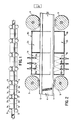
- the apparatus comprises a roller type restraining system, comprising a plurality of rollers 9, designed to transport the rail in the longitudinal direction through the spray headers and air zones, whilst keeping the rail at its required position with respect to the sprays, and restraining the rail from distortion due to uneven thermal contraction.
- a roller type restraining system comprising a plurality of rollers 9, designed to transport the rail in the longitudinal direction through the spray headers and air zones, whilst keeping the rail at its required position with respect to the sprays, and restraining the rail from distortion due to uneven thermal contraction.
- a plurality of low pressure water spray headers, la and lb alternate with a plurality of air zones, 2a and 2b, which air zones may be enclosed with shrouds.
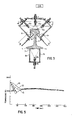
- each spray header comprises a plurality of nozzle assemblies 10a, arranged to spray cooling water on the head portion 6 of the rail, and a plurality of nozzle assemblies lOb, arranged to spray cooling water against the central portion of the base bottom 7 of the rail.
- Inclined baffles 3a are provided, to prevent any spray from nozzle assemblies 10a, from reaching rail web 4, and to prevent any drip from the sides of rail head 6, from falling on the upper surfaces of the rail base.
- Vertical lower baffles 3b confine the spray from nozzle assemblies 10b to the central portion of rail base bottom 7, preventing any portion of this spray from reaching base tips 5.
- Air zones 2a and 2b may be surrounded by close-coupled shrouds 8a and 8b to minimize fluctuations in air cooling due to any sudden changes in ambient conditions.
- Nozzle assemblies 10a and 10b are connected to a suitable source of pressurized unheated (i.e. "cold” or ambient temperature) water, or other appropriate liquid cooling medium.
- a suitable source of pressurized unheated (i.e. "cold” or ambient temperature) water i.e. "cold” or ambient temperature
- water or other appropriate liquid cooling medium.
- baffles and nozzles illustrated in Figure 3 is merely exemplary.
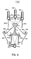
- An alternative spray header design is depicted in cross-sectional view in Figure 4.
- pipes 270 are parallel to the direction of travel of a railroad rail through the apparatus.
- Nozzle assemblies 10a and 10b are threaded into pipes 270 at longitudinally spaced intervals.
- Water inlet pipes 300 are located at the longitudinal centre of pipes 270, (i.e. at the centre of the length of pipes 270.) which pipes 270 extend substantially the length of the spray header.
- Inlet pipes 300 are connected to the water control valves and to the water supply by means of flexible hoses, which are not illustrated in Figure 4.
- dependent members 280a extend downwardly from the outer two of the three upper pipes 270.
- Baffles 310a are attached to hinges 350, which hinges are secured to supporting framework 360, which in turn is mounted on a suitable support structure.
- the function of dependent members 280a and baffles 310a is to prevent any spray from nozzle assemblies 10a from reaching web 4 and to prevent dripping from head 6 onto the upper surface of the rail base.
- lower baffles 340b confine the spray from nozzle lOb to the central portion 7 of the base bottom (7) of the rail.
- Baffles 340b are mounted on a suitable support structure. (not shown)
- Spray headers of the design depicted in Figure 4 are employed, they are of course alternated with spaced air zones as seen in Figures 1 and 2.
- Spray headers of the design as shown in Figure 4 operate in exactly the same fashion as those shown in Figures 2 and 3, but the design of Figure 4 is currently considered less expensive to manufacture and easier to maintain.
- a computer-based control system with associated entry and exit temperature monitoring systems is utilized to control the operation of the system.
- the head 6 and base bottom 7 are intermittently cooled by the water sprays in such a manner that heat soak-back during its passage through the alternating air zones is sufficient to keep the near surface region of the rail essentially _above the martensite formation temperature.
- the rail head is cooled as quickly as possible until it reaches a predetermined cooling stop temperature.
- the cooling stop temperature is the temperature of the rail when forced cooling is ceased.
- the water sprays are turned off and the rail is allowed to cool in air.
- FIGs 6 and 7 graphically compare the cooling approach taught in the previously mentioned prior art with that achieved in the present invention.
- the continuous cooling transformation curves shown in Figures 6 and 7 are well understood by those skilled in the art of rail steel metallurgy.
- the slope of the cooling curve from the Ae 3 temperature to the transformation start temperature is critical and must be controlled within very tight tolerances in order to avoid the formation of martensite or large volume fractions of bainite while still achieving the desired fine pearlite.
- the Ae 3 temperature is the upper austenite to ferrite transition temperature at an infinitely slow cooling rate.
- cooling described by line 10-11 would result in the formation of martensite. Cooling along line 10-12 results in large volume fraction of bainite.
- Cooling in the region bounded by lines 10-13 and 10-14 results in the desired fine pearlite. Cooling at rates slower than described by line 10-14 results in deterioration of rail physical properties due to increasingly coarse pearlite being formed.
- cooling from above the austenite to ferrite transformation temperature anywhere in the region bounded by lines 15-16-20 and 15-19-20 in Figure 7 achieves the desired fine pearlite.
- the effect of varying the cooling stop temperature is shown in the examples given below.
- the forced cooling of the rail base bottom is designed to help keep the rail straight within the roller restraining system by approximately balancing thermal contraction and stresses associated with metallurgical transformations top to bottom during forced cooling.
- the hot web is above the stress relieving temperature and, therefore, induced stresses will be released immediately.
- the base tips, 5, are kept as hot as possible during the forced cooling in order to prevent over-cooling these areas which could cause the formation of martensite.
- shrouds 8a and 8b around the rail in the air cooling zones help prevent convective heat loss and prevent unpredictable changes in the ambient conditions around the rail. They are designed to help stabilize the characteristics of the time-temperature cooling curve discussed above and illustrated in Figure 5 during the heat soak-back stages, represented by steps 24 in curve 21 of Figure 5, between water headers.
- shrouds 8a and 8b are optional in most operational environments. But, if the apparatus and method are employed in an environment subject to large ambient temperature variations then the use of shrouds 8a and 8b is advisable.
- roller type restraining system is designed to transport the rail in a head-up position through the water sprays and air zones. It is designed to compensate for the camber that cannot be corrected by the top and bottom cooling and it keeps the rail in the proper location with respect to the water spray nozzles and baffles within the spray headers.
- the detailed design of the roller restraining system would be obvious to those skilled in the art of mechanical engineering and therefore will not be further described herein.
- the computer-based process control system is designed to monitor the rail head temperature as it enters the first water spray header and to automatically adjust the process to compensate for the temperature variation between rails and within the length of any particular rail in order to achieve the desired constant stop temperature.
- Lengths of standard 136 lb. per yard railroad rails with the chemical composition shown in Table I were force cooled by the method herein disclosed with varying cooling stop temperatures in the range of 850 to 1200°F.
- Figure 8 shows the correlation achieved between the cooling stop temperature and strength.
- the upper curve (25) in Figure 8 represents the variation in the tensile strength, expressed in kilopounds per square inch (ksi) as a function of cooling stop temperature.
- yield strength also expressed in kilopounds per square inch, is plotted as a function of cooling stop temperature.
- Figures 9 and 10 show hardness profiles, expressed in Rockwell C hardness units, achieved as functions of distance from the running surfaces of. the rail head and cooling stop temperatures. For example, in each of Figures 9 and 10, there is a curve representing the variation of hardness as a function of distance from the rail head for a cooling stop temperature of 1080°F.
- a computer based control system appropriate to the process herein disclosed may comprise the following elements:
- the programming within the computer contains thermodynamic data, heat transfer information characterizing the cooling equipment and allowable process tolerances.
- the computer automatically activates the flow of water through the correct number of coolant headers required to achieve the desired cooling stop temperature.
- Figure llA illustrates the control system for turning off or on an appropriate number of spray headers to achieve the desired forced cooling of a railroad rail.
- the temperature of the incoming or head end of the rail is measured. The value of the measured temperature is used to turn on the flow of coolant through a suitable number of spray headers in order to obtain the desired cooling effect, given the speed of the rail through the apparatus.
- additional temperature samples of the rail progressing through the apparatus are taken at the entrance to the apparatus and the number of operating coolant headers is modified if necessary, to compensate for incoming temperature variation along the length of the rail so that each segment of an incoming rail is cooled within tolerance to the desired cooling stop temperature.
- the headers are turned off until the next rail enters. At that time, the logic system, depicted in Figure 11A, is again activated.
- the temperature of the rail is also sensed at the exit of the apparatus and relayed to the computer which compares it to the desired temperature. If the achieved temperature deviates from the desired temperatures by more than the programmed process tolerance, the computer signals the operating personnel via the cathode ray tube so that appropriate action can be taken (i.e. rail rejected or reapplied to a less critical order).
- the computer also has an adaptive mode whereby it automatically makes adjustments within its programming so that the temperature error is corrected in the next rail processed. (Note: The error could be due to events not detectable by the computing system such as clogged headers and operating personnel would be signalled to take corrective maintenance action).
- Figure 11B illustrates the use of the data sampled at the exit side of the apparatus.
- the system is activated and commences to measure the temperature, at various points along the rail, as it leaves the forced cooling apparatus.
- the system then enters its adaptive mode wherein the actual temperatures are compared with the predicted temperatures of the rail at the exit side of the apparatus.
- the necessary adjustments to the software, employed in the system depicted in Figure llA are made.
Landscapes
- Chemical & Material Sciences (AREA)
- Engineering & Computer Science (AREA)
- Mechanical Engineering (AREA)
- Materials Engineering (AREA)
- Thermal Sciences (AREA)
- Crystallography & Structural Chemistry (AREA)
- Physics & Mathematics (AREA)
- Metallurgy (AREA)
- Organic Chemistry (AREA)
- Heat Treatment Of Articles (AREA)
- Heat Treatments In General, Especially Conveying And Cooling (AREA)
- Metal Rolling (AREA)
- Furnace Details (AREA)
- Machines For Laying And Maintaining Railways (AREA)
- Control Of Heat Treatment Processes (AREA)
Priority Applications (1)
| Application Number | Priority Date | Filing Date | Title |
|---|---|---|---|
| AT83106235T ATE42225T1 (de) | 1982-07-06 | 1983-06-27 | Herstellungsverfahren von verbesserten eisenbahnschienen durch beschleunigtes abkuehlen in reihe mit dem herstellungswalzwerk. |
Applications Claiming Priority (2)
| Application Number | Priority Date | Filing Date | Title |
|---|---|---|---|
| CA406692 | 1982-07-06 | ||
| CA000406692A CA1193176A (en) | 1982-07-06 | 1982-07-06 | Method for the production of improved railway rails by accelerated colling in line with the production rolling mill |
Publications (3)
| Publication Number | Publication Date |
|---|---|
| EP0098492A2 true EP0098492A2 (de) | 1984-01-18 |
| EP0098492A3 EP0098492A3 (en) | 1985-04-17 |
| EP0098492B1 EP0098492B1 (de) | 1989-04-19 |
Family
ID=4123158
Family Applications (1)
| Application Number | Title | Priority Date | Filing Date |
|---|---|---|---|
| EP83106235A Expired EP0098492B1 (de) | 1982-07-06 | 1983-06-27 | Herstellungsverfahren von verbesserten Eisenbahnschienen durch beschleunigtes Abkühlen in Reihe mit dem Herstellungswalzwerk |
Country Status (7)
| Country | Link |
|---|---|
| US (1) | US4611789A (de) |
| EP (1) | EP0098492B1 (de) |
| JP (1) | JPS5974227A (de) |
| AT (1) | ATE42225T1 (de) |
| AU (1) | AU543932B2 (de) |
| CA (1) | CA1193176A (de) |
| DE (1) | DE3379646D1 (de) |
Cited By (18)
| Publication number | Priority date | Publication date | Assignee | Title |
|---|---|---|---|---|
| EP0161236A3 (en) * | 1984-05-09 | 1987-05-13 | Centre De Recherches Metallurgiques Centrum Voor Research In De Metallurgie Association Sans But Lucratif | Method and apparatus for manufacturing rails |
| EP0186373A3 (en) * | 1984-12-24 | 1987-05-20 | Nippon Steel Corporation | Method of and apparatus for heat treating rails |
| FR2603306A1 (fr) * | 1986-08-28 | 1988-03-04 | Ajax Magnethermic Corp | Procede et installation de traitement thermique de rails |
| EP0307386A1 (de) * | 1987-08-31 | 1989-03-15 | BÖHLER Gesellschaft m.b.H. | Verfahren zur Herstellung einer Titanlegierung und Verwendung einer Sprüheinrichtung zur Durchführung des Verfahrens |
| EP0307606A3 (en) * | 1987-09-11 | 1990-02-28 | Sms Schloemann-Siemag Aktiengesellschaft | Compact rolling mill train and method for rolling sections |
| EP0252895A3 (en) * | 1986-07-10 | 1990-07-18 | Centre De Recherches Metallurgiques Centrum Voor Research In De Metallurgie Association Sans But Lucratif | Method and apparatus for producing high resistant rails |
| US6170284B1 (en) | 1997-12-23 | 2001-01-09 | Sms Schloemann-Siemag Aktiengesellschaft | Apparatus for the controlled cooling of hot-rolled sections, particularly beams, directly from the rolling heat |
| EP1900830A1 (de) * | 2006-09-12 | 2008-03-19 | Panzhihua Iron and Steel (Group) Corporation | Verfahren und Vorrichtung zur Wärmebehandlung von Stahlschienen |
| WO2008077166A3 (de) * | 2006-12-22 | 2008-08-14 | Knorr Technik Gmbh | Verfahren und vorrichtung zur wärmebehandlung von metallischen langprodukten |
| EP2674504A1 (de) * | 2012-06-11 | 2013-12-18 | Siemens S.p.A. | Verfahren und System zur Wärmebehandlung von Schienen |
| WO2014146935A1 (en) * | 2013-03-18 | 2014-09-25 | Sandvik Materials Technology Deutschland Gmbh | Method for producing a steel tube including cleaning of the outer tube wall |
| US20140360715A1 (en) * | 2012-02-06 | 2014-12-11 | Jfe Steel Corporation | Rail cooling method |
| EP2987872A4 (de) * | 2013-04-17 | 2016-12-07 | Scient And Mfg Entpr Tomsk Electronic Company Ltd | Vorrichtung zum thermischen bearbeiten von schienen |
| EP2412472A4 (de) * | 2009-03-27 | 2017-03-22 | Nippon Steel & Sumitomo Metal Corporation | Verfahren und vorrichtung zur kühlung eines geschweissten schienenabschnitts |
| US9839949B2 (en) | 2013-03-18 | 2017-12-12 | Sandvik Materials Technology Deutschland Gmbh | Method for producing a steel tube including cleaning of the inner tube wall |
| US10092958B2 (en) | 2012-12-12 | 2018-10-09 | Sandvik Materials Technology Deutschland Gmbh | Processing machine and method for working the end of a pipe |
| CN109182715A (zh) * | 2018-09-19 | 2019-01-11 | 武汉钢铁有限公司 | 钢轨在线热处理平直度控制方法 |
| AT526905A1 (de) * | 2023-01-16 | 2024-08-15 | Ebner Ind Ofenbau | Durchlaufkühlvorrichtung |
Families Citing this family (22)
| Publication number | Priority date | Publication date | Assignee | Title |
|---|---|---|---|---|
| DE3518925A1 (de) * | 1985-05-25 | 1986-11-27 | Kocks Technik Gmbh & Co, 4010 Hilden | Verfahren zum kontrollierten stab- und drahtwalzen legierter staehle |
| JPS6289818A (ja) * | 1985-10-14 | 1987-04-24 | Nippon Kokan Kk <Nkk> | レ−ルの熱処理方法 |
| US5183519A (en) * | 1987-03-19 | 1993-02-02 | Chemetron-Railway Products, Inc. | Method for quenching railway rail heads |
| US4938460A (en) * | 1987-03-19 | 1990-07-03 | Chemetron-Railway Products, Inc. | Apparatus for air quenching railway heads |
| JPH03166318A (ja) * | 1989-11-27 | 1991-07-18 | Nippon Steel Corp | レールの熱処理方法 |
| DE4003363C1 (en) * | 1990-02-05 | 1991-03-28 | Voest-Alpine Industrieanlagenbau Ges.M.B.H., Linz, At | Hardening rails from rolling temp. - using appts. with manipulator engaging rail from exit roller table with support arms positioned pivotably on each side |
| JPH0723508B2 (ja) * | 1990-03-20 | 1995-03-15 | 川崎製鉄株式会社 | 薄肉h形鋼の冷却方法およびその装置 |
| DE4237991A1 (de) * | 1992-11-11 | 1994-05-19 | Schloemann Siemag Ag | Verfahren und Vorrichtung zur Abkühlung von warmgewalzten Profilen insbesondere von Schienen |
| AU663023B2 (en) * | 1993-02-26 | 1995-09-21 | Nippon Steel Corporation | Process for manufacturing high-strength bainitic steel rails with excellent rolling-contact fatigue resistance |
| DE4438822A1 (de) * | 1994-10-19 | 1996-04-25 | Mannesmann Ag | Verfahren und Vorrichtung zum Vermeiden der Unparallelität von Trägerprofilen |
| DE19649073C2 (de) | 1996-11-28 | 2000-12-07 | Carl Kramer | Vorrichtung zur Abkühlung von Strangpreßprofilen |
| KR100339893B1 (ko) * | 2000-01-31 | 2002-06-10 | 백창기 | 분기기 레일의 열처리방법 및 장치 |
| NO20011301L (no) * | 2001-03-14 | 2002-09-16 | Norsk Hydro As | Metode og utstyr for kjöling av profiler etter ekstrudering |
| DE10148305A1 (de) * | 2001-09-29 | 2003-04-24 | Sms Meer Gmbh | Verfahren und Anlage zur thermischen Behandlung von Schienen |
| ITMI20072244A1 (it) * | 2007-11-28 | 2009-05-29 | Danieli Off Mecc | Dispositivo per trattamento termico di rotaie e relativo processo |
| WO2013114600A1 (ja) * | 2012-02-02 | 2013-08-08 | Jfeスチール株式会社 | レール冷却方法およびレール冷却装置 |
| WO2019122986A1 (en) * | 2017-12-22 | 2019-06-27 | Arcelormittal | Steel section rolling mill |
| CN109825686B (zh) * | 2019-03-19 | 2020-05-12 | 上海交通大学 | 一种钢轨在线沿轨头轮廓均匀喷水的淬火冷却装置 |
| CN110201999B (zh) * | 2019-06-24 | 2024-06-25 | 常熟市龙腾特种钢有限公司 | 一种型钢生产方法和型钢生产装置 |
| EP4081437B1 (de) * | 2019-12-23 | 2026-03-04 | L.B. Foster Company | Sprühvorrichtung zum aufbringen von reibungsmodifizierendem material auf eisenbahnschienen |
| CN113416833B (zh) * | 2021-07-08 | 2022-06-10 | 包钢中铁轨道有限责任公司 | 一种钢轨焊缝热处理控制系统及热处理方法 |
| CN114289136B (zh) * | 2021-11-23 | 2022-11-08 | 江苏双星特钢有限公司 | 一种具有弹性联动式水冷散热装置的衬板 |
Family Cites Families (15)
| Publication number | Priority date | Publication date | Assignee | Title |
|---|---|---|---|---|
| US1752646A (en) * | 1926-02-23 | 1930-04-01 | Lukasczyk Jakob | Apparatus for strengthening the heads of railway rails |
| US2129670A (en) * | 1935-05-11 | 1938-09-13 | Cora M Brunner | Means for cooling rails |
| US2263621A (en) * | 1939-01-10 | 1941-11-25 | Welding Service Inc | Rail quenching apparatus and method |
| DE1220876B (de) * | 1962-04-26 | 1966-07-14 | Kloeckner Werke Ag | Verfahren zum Abkuehlen gewalzter Profile, insbesondere Schienen |
| US3266956A (en) * | 1963-11-29 | 1966-08-16 | Union Carbide Corp | Thermal hardening of rails |
| US3276924A (en) * | 1965-10-18 | 1966-10-04 | Yawata Iron & Steel Co | Method and apparatus for heattreating rail heads |
| FR90945E (fr) * | 1966-10-24 | 1968-03-08 | Lorraine Escaut Sa | Procédé et installation de traitement thermique des rails |
| SU256803A1 (ru) * | 1967-01-16 | 1983-10-30 | Украинский научно-исследовательский институт металлов | Способ сорбитизации головок рельсов |
| DE1583418B2 (de) * | 1967-08-08 | 1972-05-18 | Ukrainskij Nautschno-Issledowatelskij Institut Metallow, Charkow (Sowjetunion) | Vorrichtung zum fortlaufenden abschrecken von schienen |
| FR2109121A5 (de) * | 1970-10-02 | 1972-05-26 | Wendel Sidelor | |
| US3846183A (en) * | 1973-05-02 | 1974-11-05 | Bethlehem Steel Corp | Method of treating steel rail |
| DE2439338C2 (de) * | 1974-08-16 | 1980-08-28 | Fried. Krupp, Huettenwerke Ag, 4630 Bochum | Verfahren zur Wärmebehandlung von Schienen aus der Walzhitze |
| SU657883A1 (ru) * | 1977-03-11 | 1979-04-25 | Украинский научно-исследовательский институт металлов | Устройство дл охлаждени проката |
| US4243441A (en) * | 1979-05-09 | 1981-01-06 | National Steel Corporation | Method for metal strip temperature control |
| DE3006695C2 (de) * | 1980-02-22 | 1988-12-01 | Klöckner-Werke AG, 4100 Duisburg | Verfahren zum Wärmebehandeln von Schienen |
-
1982
- 1982-07-06 CA CA000406692A patent/CA1193176A/en not_active Expired
-
1983
- 1983-06-27 DE DE8383106235T patent/DE3379646D1/de not_active Expired
- 1983-06-27 AT AT83106235T patent/ATE42225T1/de not_active IP Right Cessation
- 1983-06-27 EP EP83106235A patent/EP0098492B1/de not_active Expired
- 1983-06-28 AU AU16318/83A patent/AU543932B2/en not_active Ceased
- 1983-07-05 JP JP58121129A patent/JPS5974227A/ja active Granted
-
1984
- 1984-11-28 US US06/675,772 patent/US4611789A/en not_active Expired - Lifetime
Cited By (27)
| Publication number | Priority date | Publication date | Assignee | Title |
|---|---|---|---|---|
| EP0161236A3 (en) * | 1984-05-09 | 1987-05-13 | Centre De Recherches Metallurgiques Centrum Voor Research In De Metallurgie Association Sans But Lucratif | Method and apparatus for manufacturing rails |
| EP0186373A3 (en) * | 1984-12-24 | 1987-05-20 | Nippon Steel Corporation | Method of and apparatus for heat treating rails |
| US4913747A (en) * | 1984-12-24 | 1990-04-03 | Nippon Steel Corporation | Method of and apparatus for heat-treating rails |
| EP0252895A3 (en) * | 1986-07-10 | 1990-07-18 | Centre De Recherches Metallurgiques Centrum Voor Research In De Metallurgie Association Sans But Lucratif | Method and apparatus for producing high resistant rails |
| FR2603306A1 (fr) * | 1986-08-28 | 1988-03-04 | Ajax Magnethermic Corp | Procede et installation de traitement thermique de rails |
| EP0307386A1 (de) * | 1987-08-31 | 1989-03-15 | BÖHLER Gesellschaft m.b.H. | Verfahren zur Herstellung einer Titanlegierung und Verwendung einer Sprüheinrichtung zur Durchführung des Verfahrens |
| EP0307606A3 (en) * | 1987-09-11 | 1990-02-28 | Sms Schloemann-Siemag Aktiengesellschaft | Compact rolling mill train and method for rolling sections |
| US5121622A (en) * | 1987-09-11 | 1992-06-16 | Sms Schloemann-Siemag Aktiegesellschaft | Method for rolling structural steel in a compact rolling mill |
| US6170284B1 (en) | 1997-12-23 | 2001-01-09 | Sms Schloemann-Siemag Aktiengesellschaft | Apparatus for the controlled cooling of hot-rolled sections, particularly beams, directly from the rolling heat |
| EP1900830A1 (de) * | 2006-09-12 | 2008-03-19 | Panzhihua Iron and Steel (Group) Corporation | Verfahren und Vorrichtung zur Wärmebehandlung von Stahlschienen |
| WO2008077166A3 (de) * | 2006-12-22 | 2008-08-14 | Knorr Technik Gmbh | Verfahren und vorrichtung zur wärmebehandlung von metallischen langprodukten |
| EP2412472A4 (de) * | 2009-03-27 | 2017-03-22 | Nippon Steel & Sumitomo Metal Corporation | Verfahren und vorrichtung zur kühlung eines geschweissten schienenabschnitts |
| US20140360715A1 (en) * | 2012-02-06 | 2014-12-11 | Jfe Steel Corporation | Rail cooling method |
| US9429374B2 (en) * | 2012-02-06 | 2016-08-30 | Jfe Steel Corporation | Rail cooling method |
| RU2637197C2 (ru) * | 2012-06-11 | 2017-11-30 | Прайметалз Текнолоджиз Итали С.Р.Л. | Способ и система для термической обработки рельсов |
| US10125405B2 (en) | 2012-06-11 | 2018-11-13 | Primetals Technologies Italy S.R.L. | Method and system for thermal treatments of rails |
| WO2013186137A1 (en) * | 2012-06-11 | 2013-12-19 | Siemens S.P.A. | Method and system for thermal treatments of rails |
| EP2674504A1 (de) * | 2012-06-11 | 2013-12-18 | Siemens S.p.A. | Verfahren und System zur Wärmebehandlung von Schienen |
| US10092958B2 (en) | 2012-12-12 | 2018-10-09 | Sandvik Materials Technology Deutschland Gmbh | Processing machine and method for working the end of a pipe |
| CN105307789A (zh) * | 2013-03-18 | 2016-02-03 | 山特维克原料技术德国公开股份有限公司 | 包括清洁外管壁的生产钢管的方法 |
| US9808844B2 (en) | 2013-03-18 | 2017-11-07 | Sandvik Materials Technology Deutschland Gmbh | Method for producing a steel tube including cleaning of the outer tube wall |
| US9839949B2 (en) | 2013-03-18 | 2017-12-12 | Sandvik Materials Technology Deutschland Gmbh | Method for producing a steel tube including cleaning of the inner tube wall |
| WO2014146935A1 (en) * | 2013-03-18 | 2014-09-25 | Sandvik Materials Technology Deutschland Gmbh | Method for producing a steel tube including cleaning of the outer tube wall |
| EP2987872A4 (de) * | 2013-04-17 | 2016-12-07 | Scient And Mfg Entpr Tomsk Electronic Company Ltd | Vorrichtung zum thermischen bearbeiten von schienen |
| CN109182715A (zh) * | 2018-09-19 | 2019-01-11 | 武汉钢铁有限公司 | 钢轨在线热处理平直度控制方法 |
| AT526905A1 (de) * | 2023-01-16 | 2024-08-15 | Ebner Ind Ofenbau | Durchlaufkühlvorrichtung |
| AT526905B1 (de) * | 2023-01-16 | 2024-12-15 | Ebner Ind Ofenbau | Durchlaufkühlvorrichtung |
Also Published As
| Publication number | Publication date |
|---|---|
| AU543932B2 (en) | 1985-05-09 |
| ATE42225T1 (de) | 1989-05-15 |
| EP0098492B1 (de) | 1989-04-19 |
| US4611789A (en) | 1986-09-16 |
| JPH0255488B2 (de) | 1990-11-27 |
| CA1193176A (en) | 1985-09-10 |
| JPS5974227A (ja) | 1984-04-26 |
| AU1631883A (en) | 1984-01-12 |
| DE3379646D1 (en) | 1989-05-24 |
| EP0098492A3 (en) | 1985-04-17 |
Similar Documents
| Publication | Publication Date | Title |
|---|---|---|
| EP0098492B1 (de) | Herstellungsverfahren von verbesserten Eisenbahnschienen durch beschleunigtes Abkühlen in Reihe mit dem Herstellungswalzwerk | |
| US4486248A (en) | Method for the production of improved railway rails by accelerated cooling in line with the production rolling mill | |
| US4913747A (en) | Method of and apparatus for heat-treating rails | |
| US10125405B2 (en) | Method and system for thermal treatments of rails | |
| EP1412543B1 (de) | Verfahren zur kühlung von werkstücken insbesondere von profilwalzprodukten aus schienenstählen | |
| US20020104597A1 (en) | Method and apparatus for producing steel | |
| JPH0310023A (ja) | 熱間圧延鋼線材の直接急冷方法 | |
| US5004510A (en) | Process for manufacturing high strength railroad rails | |
| US20220112571A1 (en) | Method of producing steel material, apparatus that cools steel material, and steel material | |
| CA2154090C (en) | Method and apparatus for heat-treating profiled rolling stock | |
| US4668308A (en) | Method and apparatus for manufacturing rails | |
| US6170284B1 (en) | Apparatus for the controlled cooling of hot-rolled sections, particularly beams, directly from the rolling heat | |
| CA1307723C (en) | Process and apparatus for manufacturing a high strength rail | |
| JP3101980B2 (ja) | 熱間圧延鋼線材の直接急冷方法 | |
| JPS6160827A (ja) | 高温レ−ルの形状矯正冷却法 | |
| RU2705820C1 (ru) | Способ термической обработки сварных соединений рельсов и устройство для осуществления способа | |
| JP2773867B2 (ja) | 高温レールの冷却法 | |
| CN117999452A (zh) | 用于冷却长钢产品的强制风冷 | |
| Augusti | In-line thermal treatment applies to straight and coiled rebars | |
| UA61059C2 (uk) | Спосіб термічної обробки рейок | |
| CN109402352A (zh) | 一种在线淬火制造护轨用槽型钢的工艺 |
Legal Events
| Date | Code | Title | Description |
|---|---|---|---|
| PUAI | Public reference made under article 153(3) epc to a published international application that has entered the european phase |
Free format text: ORIGINAL CODE: 0009012 |
|
| 17P | Request for examination filed |
Effective date: 19830627 |
|
| AK | Designated contracting states |
Designated state(s): AT BE CH DE FR GB IT LI LU NL SE |
|
| PUAL | Search report despatched |
Free format text: ORIGINAL CODE: 0009013 |
|
| AK | Designated contracting states |
Designated state(s): AT BE CH DE FR GB IT LI LU NL SE |
|
| 17Q | First examination report despatched |
Effective date: 19861020 |
|
| GRAA | (expected) grant |
Free format text: ORIGINAL CODE: 0009210 |
|
| AK | Designated contracting states |
Kind code of ref document: B1 Designated state(s): AT BE CH DE FR GB IT LI LU NL SE |
|
| PG25 | Lapsed in a contracting state [announced via postgrant information from national office to epo] |
Ref country code: NL Effective date: 19890419 Ref country code: BE Effective date: 19890419 |
|
| REF | Corresponds to: |
Ref document number: 42225 Country of ref document: AT Date of ref document: 19890515 Kind code of ref document: T |
|
| REF | Corresponds to: |
Ref document number: 3379646 Country of ref document: DE Date of ref document: 19890524 |
|
| ITF | It: translation for a ep patent filed | ||
| PG25 | Lapsed in a contracting state [announced via postgrant information from national office to epo] |
Ref country code: LI Free format text: LAPSE BECAUSE OF NON-PAYMENT OF DUE FEES Effective date: 19890630 Ref country code: CH Free format text: LAPSE BECAUSE OF NON-PAYMENT OF DUE FEES Effective date: 19890630 |
|
| REG | Reference to a national code |
Ref country code: CH Ref legal event code: PL |
|
| ET | Fr: translation filed | ||
| NLV1 | Nl: lapsed or annulled due to failure to fulfill the requirements of art. 29p and 29m of the patents act | ||
| PLBI | Opposition filed |
Free format text: ORIGINAL CODE: 0009260 |
|
| 26 | Opposition filed |
Opponent name: CENTRE DE RECHERCHES METALLURGIQUES ASSOCIATION SA Effective date: 19900108 Opponent name: BRITISH STEEL PLC Effective date: 19891230 |
|
| PGFP | Annual fee paid to national office [announced via postgrant information from national office to epo] |
Ref country code: GB Payment date: 19910327 Year of fee payment: 9 |
|
| PGFP | Annual fee paid to national office [announced via postgrant information from national office to epo] |
Ref country code: SE Payment date: 19910624 Year of fee payment: 9 |
|
| PGFP | Annual fee paid to national office [announced via postgrant information from national office to epo] |
Ref country code: FR Payment date: 19910625 Year of fee payment: 9 |
|
| PGFP | Annual fee paid to national office [announced via postgrant information from national office to epo] |
Ref country code: LU Payment date: 19910626 Year of fee payment: 9 |
|
| PGFP | Annual fee paid to national office [announced via postgrant information from national office to epo] |
Ref country code: AT Payment date: 19910628 Year of fee payment: 9 |
|
| ITTA | It: last paid annual fee | ||
| PGFP | Annual fee paid to national office [announced via postgrant information from national office to epo] |
Ref country code: DE Payment date: 19910829 Year of fee payment: 9 |
|
| EPTA | Lu: last paid annual fee | ||
| PG25 | Lapsed in a contracting state [announced via postgrant information from national office to epo] |
Ref country code: LU Free format text: LAPSE BECAUSE OF NON-PAYMENT OF DUE FEES Effective date: 19920627 Ref country code: GB Effective date: 19920627 Ref country code: AT Effective date: 19920627 |
|
| PG25 | Lapsed in a contracting state [announced via postgrant information from national office to epo] |
Ref country code: SE Effective date: 19920628 |
|
| GBPC | Gb: european patent ceased through non-payment of renewal fee |
Effective date: 19920627 |
|
| PG25 | Lapsed in a contracting state [announced via postgrant information from national office to epo] |
Ref country code: FR Effective date: 19930226 |
|
| PG25 | Lapsed in a contracting state [announced via postgrant information from national office to epo] |
Ref country code: DE Effective date: 19930302 |
|
| REG | Reference to a national code |
Ref country code: FR Ref legal event code: ST |
|
| RDAG | Patent revoked |
Free format text: ORIGINAL CODE: 0009271 |
|
| STAA | Information on the status of an ep patent application or granted ep patent |
Free format text: STATUS: PATENT REVOKED |
|
| 27W | Patent revoked |
Effective date: 19931103 |
|
| REG | Reference to a national code |
Ref country code: CH Ref legal event code: PL |
|
| EUG | Se: european patent has lapsed |
Ref document number: 83106235.1 Effective date: 19930109 |
|
| APAH | Appeal reference modified |
Free format text: ORIGINAL CODE: EPIDOSCREFNO |