EP0098621B1 - Mischventil für Warm- und Kaltwasser - Google Patents
Mischventil für Warm- und Kaltwasser Download PDFInfo
- Publication number
- EP0098621B1 EP0098621B1 EP83200099A EP83200099A EP0098621B1 EP 0098621 B1 EP0098621 B1 EP 0098621B1 EP 83200099 A EP83200099 A EP 83200099A EP 83200099 A EP83200099 A EP 83200099A EP 0098621 B1 EP0098621 B1 EP 0098621B1
- Authority
- EP
- European Patent Office
- Prior art keywords
- valve
- valve member
- mixing
- water
- cylindrical socket
- Prior art date
- Legal status (The legal status is an assumption and is not a legal conclusion. Google has not performed a legal analysis and makes no representation as to the accuracy of the status listed.)
- Expired
Links
- XLYOFNOQVPJJNP-UHFFFAOYSA-N water Substances O XLYOFNOQVPJJNP-UHFFFAOYSA-N 0.000 title claims abstract description 47
- 238000007689 inspection Methods 0.000 claims abstract description 11
- 230000000694 effects Effects 0.000 claims abstract description 3
- 239000000470 constituent Substances 0.000 description 3
- 230000002950 deficient Effects 0.000 description 3
- 230000003628 erosive effect Effects 0.000 description 3
- OKTJSMMVPCPJKN-UHFFFAOYSA-N Carbon Chemical compound [C] OKTJSMMVPCPJKN-UHFFFAOYSA-N 0.000 description 2
- 238000010276 construction Methods 0.000 description 2
- 210000004907 gland Anatomy 0.000 description 2
- 229910002804 graphite Inorganic materials 0.000 description 2
- 239000010439 graphite Substances 0.000 description 2
- 238000012423 maintenance Methods 0.000 description 2
- 229910001369 Brass Inorganic materials 0.000 description 1
- 241001415961 Gaviidae Species 0.000 description 1
- 230000000903 blocking effect Effects 0.000 description 1
- 239000010951 brass Substances 0.000 description 1
- 230000001419 dependent effect Effects 0.000 description 1
- 210000000245 forearm Anatomy 0.000 description 1
- 238000009434 installation Methods 0.000 description 1
- 238000003475 lamination Methods 0.000 description 1
- 239000010985 leather Substances 0.000 description 1
- 239000007788 liquid Substances 0.000 description 1
- 239000002184 metal Substances 0.000 description 1
- 238000000034 method Methods 0.000 description 1
- 238000012856 packing Methods 0.000 description 1
- 238000005192 partition Methods 0.000 description 1
- 230000035939 shock Effects 0.000 description 1
- 229920002994 synthetic fiber Polymers 0.000 description 1
- 230000000007 visual effect Effects 0.000 description 1
Images


Classifications
-
- F—MECHANICAL ENGINEERING; LIGHTING; HEATING; WEAPONS; BLASTING
- F16—ENGINEERING ELEMENTS AND UNITS; GENERAL MEASURES FOR PRODUCING AND MAINTAINING EFFECTIVE FUNCTIONING OF MACHINES OR INSTALLATIONS; THERMAL INSULATION IN GENERAL
- F16K—VALVES; TAPS; COCKS; ACTUATING-FLOATS; DEVICES FOR VENTING OR AERATING
- F16K31/00—Actuating devices; Operating means; Releasing devices
- F16K31/44—Mechanical actuating means
- F16K31/52—Mechanical actuating means with crank, eccentric, or cam
- F16K31/524—Mechanical actuating means with crank, eccentric, or cam with a cam
- F16K31/52408—Mechanical actuating means with crank, eccentric, or cam with a cam comprising a lift valve
- F16K31/52416—Mechanical actuating means with crank, eccentric, or cam with a cam comprising a lift valve comprising a multiple-way lift valve
-
- F—MECHANICAL ENGINEERING; LIGHTING; HEATING; WEAPONS; BLASTING
- F16—ENGINEERING ELEMENTS AND UNITS; GENERAL MEASURES FOR PRODUCING AND MAINTAINING EFFECTIVE FUNCTIONING OF MACHINES OR INSTALLATIONS; THERMAL INSULATION IN GENERAL
- F16K—VALVES; TAPS; COCKS; ACTUATING-FLOATS; DEVICES FOR VENTING OR AERATING
- F16K11/00—Multiple-way valves, e.g. mixing valves; Pipe fittings incorporating such valves
- F16K11/10—Multiple-way valves, e.g. mixing valves; Pipe fittings incorporating such valves with two or more closure members not moving as a unit
- F16K11/14—Multiple-way valves, e.g. mixing valves; Pipe fittings incorporating such valves with two or more closure members not moving as a unit operated by one actuating member, e.g. a handle
- F16K11/16—Multiple-way valves, e.g. mixing valves; Pipe fittings incorporating such valves with two or more closure members not moving as a unit operated by one actuating member, e.g. a handle which only slides, or only turns, or only swings in one plane
- F16K11/163—Multiple-way valves, e.g. mixing valves; Pipe fittings incorporating such valves with two or more closure members not moving as a unit operated by one actuating member, e.g. a handle which only slides, or only turns, or only swings in one plane only turns
- F16K11/166—Multiple-way valves, e.g. mixing valves; Pipe fittings incorporating such valves with two or more closure members not moving as a unit operated by one actuating member, e.g. a handle which only slides, or only turns, or only swings in one plane only turns with the rotating spindles at right angles to the closure members
Definitions
- the subject of the present invention is a mixing tap for hot and cold water comprising a monobloc body, provided with a mixing spout and, on either side of the mixing spout, with two pipes for connection to a network.
- hot water distribution system and to a cold water distribution network a member for adjusting the temperature of the water that is withdrawn, a first shutter disposed between the connection pipe to the cold water network and the mixing spout and a second shutter similar to the first, arranged between the connection pipe to the hot water network and said mixing spout.
- It also relates to a process for establishing and suspending at will the flow and the temperature of the water using the aforementioned tap.
- the invention finds its main application in sanitary installations for mixing two liquids in a variable proportion. It is particularly suitable for patient rooms in hospitals and for doctor's handwashers in medical offices and operating theaters.
- a mixer tap for hot and cold water corresponding to the preamble of claim 1 and comprising a one-piece body provided with a mixing spout, on both sides mixing spout, two pipes for connection to a hot water distribution network and a cold water distribution network.
- This known mixing valve has two separate shutter boxes, actuated simultaneously by a single manual adjustment member operated with one hand. The shutter boxes are put in place as such, in the body of the valve, when it is assembled in the factory, the first being placed between the connection pipe to the cold water network and the mixing spout and the second between the connection pipe to the hot water network and said mixing spout.
- These shutters each consist of a needle valve mounted on a rod.
- the major drawback of this known mixing valve lies in the fact that the replacement of a worn or defective housing requires the disconnection of one or the other water supply pipe from the distribution network and the dismantling of certain parts of the valve body, to be able to remove the valve plug. It is also observed that the guide rod provided with fins slides along a sleeve. In this embodiment, the guide rod has the disadvantage of being easily blocked by limescale.
- Swiss patent CH-A-444 072 describes a mixing valve comprising two needle valves actuated simultaneously by a single manual adjustment member.
- the valve, seat and coil spring are mounted in an externally threaded sleeve. Replacement of the shutter device is made difficult.
- the guide rod, supported by an internal partition, forms a linkage subjected to violent vibrations.
- the present invention aims to remedy these drawbacks.
- it solves the problem of replacing worn or defective valve housings by making it possible to insert the valve housings in the body of the mixing valve, without requiring the disconnection of the pipes of the water pipes.
- the invention proposes to arrange in the body of the mixer tap inspection ports distinct from the connection orifices. These inspection openings are easily accessible by unscrewing and removing an inspection plug. They are dimensioned in such a way that the shutter box can be inserted and removed as is from the valve body. The replacement of a defective shutter box is thus considerably simplified, since it is not even necessary to disconnect the connecting pipes to the cold and hot water networks. A visual check of the shutter device is also made possible.
- the guide rod has a squat cylindrical shape in which recesses are formed in arcs of a circle, in order to guide the water streams and prevent erosion.
- the mixing chamber is formed by the cavity of the cam, which makes it possible to produce a frame consisting of a single piece, free of intermediate annular walls.
- the valve according to the invention is distinguished by the construction of a one-piece body and the design of a guide rod ensuring an operation free of vibrations and erosion, the profiling of a seat. and a valve ensuring a perfect seal for high water pressures.
- each obturator housing consists of a seat and a conical port valve integral with a piston deposited in the vicinity of the mixing spout and simultaneously controlled by a cam actuated by means of the above single setting.
- the aforementioned shutters are of the “water pressure closure” type.
- each obturator is respectively a cylindrical sleeve provided at one end with a gripping groove and at the other end with a connecting thread and a base , and intended to be mounted on a threaded ring serving as a seat, as well as a conical valve integral with a piston which can slide along the ring and the aforementioned sleeve.
- each shutter is held in place by said bushing and said ring, constituting a housing capable of being introduced by one of the inspection orifices provided on either side of the body of the above-mentioned tap and to be fixed by screwing and blocking in the body of the above-mentioned mixing tap.
- each of the shutters is advantageously furnished with a conical elastic seal held in place by a lateral face of the ring and by the base of the socket mounted on the aforesaid ring.
- This elastic seal has the advantage of offering a perfectly sealed closure.
- the single adjustment member is advantageously a lever, which preferably pivots about a substantially vertical axis perpendicular to the longitudinal axis of the body of the mixing valve.
- the invention makes it possible to establish and suspend at will the flow and regulate the temperature of the water which is withdrawn, using a mixing tap of hot and cold water.
- a linear movement is transmitted using a cam actuated by a single adjusting member to at least one of the valves of the shutters of the above-mentioned mixing valve.
- the above-mentioned valve is actuated by rotating a lever around a substantially vertical axis.
- the return force of each valve with conical bearing on its seat is increased by means of a spring, acting on the base of the valve.
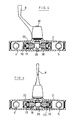
- a mixing valve according to the invention designated as a whole by the reference notation 1, comprises in a particular construction mode a monobloc body 2, provided with a mixing spout 3 and, on each side the mixing spout 3, two pipes 4, 5 for connection using connection nuts 6 to a hot water distribution network and to a cold water distribution network, the pipes of which are not shown are hidden by two chromed metal discs 7.
- an adjustment lever 8 which can pivot around a substantially vertical axis 9.
- the adjustment lever 8 is fixed with a screw 10 to a shaft not shown, materializing the axis 9 above.
- inspection openings 11 normally blocked each by a seal 12 and an inspection plug 13.
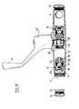
- FIG. 2 A vertical section of the above-mentioned mixing tap is shown in FIG. 2.
- Two shutter boxes 14, 15 are mounted on either side of the axis 9 between the mixing spout 3 and each pipe 4, 5 for connection to the network d hot and cold water respectively.
- Each obturator housing 14, 15 consists of a seat 25 and a valve 17 with conical bearing, integral with a guide rod 18, disposed in the vicinity of the mixing spout 3.
- the valve 17 has a substantially flat face 17 '.
- the shutter boxes 14 and 15 are controlled simultaneously by a cam 26 actuated by means of the single adjustment lever 8.
- each of the valve housings 14 and 15, that is to say the seats 25, the valves 17, the guide rods 18 and possibly the closing return springs 19, are mounted and held in place in a cylindrical sleeve 20 provided at one end with a gripping groove 21 and at the other end with a connecting thread 22 and a base and intended to be mounted on a threaded ring 24 serving as a seat 25.
- each of the shutters 14, 15 is lined with a conical seal 25 held in place by a lateral face of the ring 24 and by the base of the cylindrical sleeve 20 mounted on the aforesaid ring.
- the piston rod advantageously has recesses in the form of arcs of a circle 18 ′ intended to direct the streams of water. These recesses reduce lamination and prevent erosion of the conical seal of the seats ( Figure 3).
- Said cam 26 is fixed to a substantially vertical shaft 27 made of brass, pivotally mounted in the one-piece body 2 of the mixing valve 1 perpendicular to the plane formed by the longitudinal axis 9 and the mixing spout 3.
- the shaft 27 is supported at one end on a stop 28 provided with a stop washer 29 made of synthetic material and at the other end on a seal 32. It has at this other end a notch 30 which s fits perfectly into a recess 31 of the adjustment handle 8.
- the adjustment of the adjustment handle 8 is carried out simply using a fixing screw 10.
- the seal 32 consists of a first ring 33 and a second ring 34 externally threaded, provided on an upper face with a fixing groove 35 allowing them to be screwed using a suitable tool not shown, for example a large screwdriver, in a threaded cavity 36 of the one-piece body 2 of the mixing valve 1.
- the ring 34 serves to support a double washer 37 which is integral with the shaft 20 and which holds an annular seal in place rubber or "o-ring" 38.
- the ring 33 also serves as a support for a cable gland 39 disposed above it and intended to reinforce the tightness of the “o-ring” 38.
- the cable gland 39 has a graphite packing seal 40 trimmed on both sides with a leather washer 41.
- the second ring 34 serves as a stuffing press and compresses the graphite seal 40.
- the adjustment lever has a cap 42 which covers the seal 32.
- the cam 26 has a substantially triangular section with rounded corners as shown in FIG. 8 This cam 26 possibly acts on the piston 18 of each of the shutters.
- FIGS. 3 to 6 showing the various positions of the shutters 14, 15 as a function of the position of the adjustment lever 8.
- the control of the mixing valve is obtained by actuation of a single adjustment handle.
- the pivoting of this adjustment handle around the vertical axis at an angle of 120 ° allows the adjustment of both the flow rate and the temperature of the water.
- the positioning of the joystick can be easily done using the elbow or forearm. As a result, a surgeon for example does not risk contaminating his hands in an operating theater fitted with such taps.
- the initial closed position of the valve is shown in Figure 4.
- the conical port of the valve 17 of each of the valve housings 14, 15 is supported on their seat 16.
- the valves 17 are supported on the seats under the effect of the water pressure exerted on their substantially flat base 17 ′.
- a closing return spring 33 exerts a thrust on the substantially flat base of the above-mentioned valve 17 to ensure faster closing in the event of low water pressure.
- each of the shutters consisting of the valve-piston assembly which slides along the guide constituted by the sleeve 20 is approximately a quarter of the diameter of the orifice of the seat of the shutter 14, 15.
- the component parts of the valve housings 14 and 15 are of easy access. They can be easily introduced into the one-piece body 2 of the tap 1 through one of the orifices 11 provided for this purpose after having removed the inspection plug 13.
- the assembly of the socket 20 containing the constituent parts of the shutter 14, 15 is carried out by screwing on the ring 24 using a clamping tool (not shown) fitting in the grooves 21 of the sleeve 20.
- the disassembly is carried out in a similar manner by unscrewing the sleeve 20 above.
- valves in the immediate vicinity of the cam and the particular shape of the pistons having recesses in an arc prevent any vibration during the flow of water.
Landscapes
- Engineering & Computer Science (AREA)
- General Engineering & Computer Science (AREA)
- Mechanical Engineering (AREA)
- Multiple-Way Valves (AREA)
- Secondary Cells (AREA)
- Domestic Plumbing Installations (AREA)
Claims (4)
Priority Applications (1)
| Application Number | Priority Date | Filing Date | Title |
|---|---|---|---|
| AT83200099T ATE28354T1 (de) | 1982-07-05 | 1983-01-24 | Mischventil fuer warm- und kaltwasser. |
Applications Claiming Priority (2)
| Application Number | Priority Date | Filing Date | Title |
|---|---|---|---|
| BE0/208534A BE893761A (fr) | 1982-07-05 | 1982-07-05 | Robinet melangeur d'eau chaude et d'eau froide |
| BE208534 | 1982-07-05 |
Publications (2)
| Publication Number | Publication Date |
|---|---|
| EP0098621A1 EP0098621A1 (de) | 1984-01-18 |
| EP0098621B1 true EP0098621B1 (de) | 1987-07-15 |
Family
ID=3843544
Family Applications (1)
| Application Number | Title | Priority Date | Filing Date |
|---|---|---|---|
| EP83200099A Expired EP0098621B1 (de) | 1982-07-05 | 1983-01-24 | Mischventil für Warm- und Kaltwasser |
Country Status (4)
| Country | Link |
|---|---|
| EP (1) | EP0098621B1 (de) |
| AT (1) | ATE28354T1 (de) |
| DE (1) | DE3372530D1 (de) |
| DK (1) | DK162362C (de) |
Families Citing this family (1)
| Publication number | Priority date | Publication date | Assignee | Title |
|---|---|---|---|---|
| CN111895140A (zh) * | 2020-08-04 | 2020-11-06 | 厦门吉科卫浴有限公司 | 一种水路切换装置及淋浴设备 |
Family Cites Families (11)
| Publication number | Priority date | Publication date | Assignee | Title |
|---|---|---|---|---|
| FR807032A (fr) * | 1935-06-05 | 1936-12-31 | Robinet mélangeur | |
| FR1188365A (fr) * | 1957-12-14 | 1959-09-22 | Valve pour robinet mitigeur | |
| FR1257738A (fr) * | 1960-02-23 | 1961-04-07 | Perfectionnements aux robinets mitigeurs | |
| FR1307336A (fr) * | 1961-09-13 | 1962-10-26 | Bricard | Dispositif à came pour la distribution d'eau froide, mitigée ou chaude |
| US3207183A (en) * | 1963-04-02 | 1965-09-21 | Karrer Weber & Cie Ag | Cam operated mixing valve |
| CH411497A (de) * | 1963-07-30 | 1966-04-15 | Karrer Weber & Cie Ag | Mischbatterie für Gasautomaten |
| FR1395726A (fr) * | 1964-03-04 | 1965-04-16 | Mitigeur | |
| FR1408753A (fr) * | 1964-06-22 | 1965-08-20 | Robinet mélangeur mitigeur à grande plage de réglage | |
| US3403700A (en) * | 1966-05-09 | 1968-10-01 | Meynell & Sons Ltd | Fluid mixing valve with adjustable cam actuator |
| CH444072A (de) * | 1967-01-12 | 1967-09-15 | Karrer Weber & Cie Ag | Mechanisch gesteuerte Mischbatterie |
| FR1561423A (de) * | 1968-02-12 | 1969-03-28 |
-
1983
- 1983-01-24 AT AT83200099T patent/ATE28354T1/de not_active IP Right Cessation
- 1983-01-24 EP EP83200099A patent/EP0098621B1/de not_active Expired
- 1983-01-24 DE DE8383200099T patent/DE3372530D1/de not_active Expired
- 1983-07-05 DK DK311283A patent/DK162362C/da not_active IP Right Cessation
Also Published As
| Publication number | Publication date |
|---|---|
| DK162362C (da) | 1992-03-09 |
| DK311283A (da) | 1984-01-06 |
| EP0098621A1 (de) | 1984-01-18 |
| DE3372530D1 (en) | 1987-08-20 |
| DK162362B (da) | 1991-10-14 |
| DK311283D0 (da) | 1983-07-05 |
| ATE28354T1 (de) | 1987-08-15 |
Similar Documents
| Publication | Publication Date | Title |
|---|---|---|
| CA1263358A (fr) | Robinet de regulation | |
| EP2021664B1 (de) | Ventil | |
| EP1048997A1 (de) | Kartusche für ein Mischventil mit Temperaturbegrenzung | |
| FR2993337A1 (fr) | Robinet a bague de manoeuvre axiale dispositif d'ouverture/fermeture de canalisation pour passage de fluides ou gaz par bague de manoeuvre axiale tournante | |
| FR2791409A1 (fr) | Raccord de robinetterie pour un reservoir sous pression | |
| FR2757601A1 (fr) | Ensemble de poignee de robinet | |
| CA1261311A (fr) | Dispositif d'obturation pour conduite vehiculant un fluide | |
| EP1352190A1 (de) | Pneumatisch angesteuertes ventil | |
| EP0098621B1 (de) | Mischventil für Warm- und Kaltwasser | |
| EP0426587A1 (de) | Mischventil für sanitäre Anlage | |
| FR2487473A1 (fr) | Vanne melangeuse, notamment pour eau chaude et eau froide pour installations sanitaires | |
| FR2753771A1 (fr) | Cartouche de robinet mitigeur a limitation ajustable de debit | |
| US3847181A (en) | Faucet | |
| EP0041007A1 (de) | Druckrelais zur Positionsangabe des beweglichen Teils eines Arbeitzylinders | |
| BE893761A (fr) | Robinet melangeur d'eau chaude et d'eau froide | |
| FR2695183A1 (fr) | Soupape pilote, destinée notamment à être utilisée dans un système hydraulique d'exploitation minière. | |
| EP3446192B1 (de) | Mischeinheit und mischarmatur mit solch einer mischeinheit | |
| US6938878B2 (en) | Direct flow tap for dispensing drinks, provided with improved devices for stopping the operating handle | |
| FR2515772A1 (fr) | Mitigeur a commande unique pour appareils sanitaires | |
| FR2499664A1 (fr) | Robinet melangeur a manette unique | |
| FR2700597A1 (fr) | Clapet de distribution de fluide. | |
| FR2466692A1 (fr) | Robinet melangeur a commande par excentrique | |
| EP0080421A1 (de) | Wassermischbatterie | |
| EP0507716B1 (de) | Vorrichtung zur Isolierung und Verbindung von mehreren Fliesswegen für Flüssigkeiten und Hahn mit einer derartigen Vorrichtung | |
| EP0356364A1 (de) | Speziell für Plastikrohre geeignete Verbindung |
Legal Events
| Date | Code | Title | Description |
|---|---|---|---|
| PUAI | Public reference made under article 153(3) epc to a published international application that has entered the european phase |
Free format text: ORIGINAL CODE: 0009012 |
|
| AK | Designated contracting states |
Designated state(s): AT CH DE FR GB IT LI LU NL SE |
|
| 17P | Request for examination filed |
Effective date: 19831231 |
|
| ITF | It: translation for a ep patent filed | ||
| GRAA | (expected) grant |
Free format text: ORIGINAL CODE: 0009210 |
|
| AK | Designated contracting states |
Kind code of ref document: B1 Designated state(s): AT CH DE FR GB IT LI LU NL SE |
|
| REF | Corresponds to: |
Ref document number: 28354 Country of ref document: AT Date of ref document: 19870815 Kind code of ref document: T |
|
| REF | Corresponds to: |
Ref document number: 3372530 Country of ref document: DE Date of ref document: 19870820 |
|
| PLBE | No opposition filed within time limit |
Free format text: ORIGINAL CODE: 0009261 |
|
| STAA | Information on the status of an ep patent application or granted ep patent |
Free format text: STATUS: NO OPPOSITION FILED WITHIN TIME LIMIT |
|
| 26N | No opposition filed | ||
| ITTA | It: last paid annual fee | ||
| EPTA | Lu: last paid annual fee | ||
| PGFP | Annual fee paid to national office [announced via postgrant information from national office to epo] |
Ref country code: SE Payment date: 19941216 Year of fee payment: 13 |
|
| PGFP | Annual fee paid to national office [announced via postgrant information from national office to epo] |
Ref country code: CH Payment date: 19941222 Year of fee payment: 13 |
|
| PGFP | Annual fee paid to national office [announced via postgrant information from national office to epo] |
Ref country code: FR Payment date: 19950104 Year of fee payment: 13 |
|
| PGFP | Annual fee paid to national office [announced via postgrant information from national office to epo] |
Ref country code: AT Payment date: 19950126 Year of fee payment: 13 |
|
| EAL | Se: european patent in force in sweden |
Ref document number: 83200099.6 |
|
| PG25 | Lapsed in a contracting state [announced via postgrant information from national office to epo] |
Ref country code: AT Effective date: 19960124 |
|
| PG25 | Lapsed in a contracting state [announced via postgrant information from national office to epo] |
Ref country code: SE Effective date: 19960125 |
|
| PG25 | Lapsed in a contracting state [announced via postgrant information from national office to epo] |
Ref country code: CH Effective date: 19960131 Ref country code: LI Effective date: 19960131 |
|
| REG | Reference to a national code |
Ref country code: CH Ref legal event code: PL |
|
| PG25 | Lapsed in a contracting state [announced via postgrant information from national office to epo] |
Ref country code: FR Effective date: 19960930 |
|
| EUG | Se: european patent has lapsed |
Ref document number: 83200099.6 |
|
| PGFP | Annual fee paid to national office [announced via postgrant information from national office to epo] |
Ref country code: LU Payment date: 19961101 Year of fee payment: 15 |
|
| REG | Reference to a national code |
Ref country code: FR Ref legal event code: ST |
|
| PGFP | Annual fee paid to national office [announced via postgrant information from national office to epo] |
Ref country code: DE Payment date: 19961228 Year of fee payment: 15 |
|
| PG25 | Lapsed in a contracting state [announced via postgrant information from national office to epo] |
Ref country code: LU Free format text: LAPSE BECAUSE OF NON-PAYMENT OF DUE FEES Effective date: 19980124 |
|
| PG25 | Lapsed in a contracting state [announced via postgrant information from national office to epo] |
Ref country code: DE Free format text: LAPSE BECAUSE OF NON-PAYMENT OF DUE FEES Effective date: 19981001 |
|
| PGFP | Annual fee paid to national office [announced via postgrant information from national office to epo] |
Ref country code: GB Payment date: 19981127 Year of fee payment: 17 |
|
| PGFP | Annual fee paid to national office [announced via postgrant information from national office to epo] |
Ref country code: NL Payment date: 19990129 Year of fee payment: 17 |
|
| PG25 | Lapsed in a contracting state [announced via postgrant information from national office to epo] |
Ref country code: GB Free format text: LAPSE BECAUSE OF NON-PAYMENT OF DUE FEES Effective date: 20000124 |
|
| PG25 | Lapsed in a contracting state [announced via postgrant information from national office to epo] |
Ref country code: NL Free format text: LAPSE BECAUSE OF NON-PAYMENT OF DUE FEES Effective date: 20000801 |
|
| GBPC | Gb: european patent ceased through non-payment of renewal fee |
Effective date: 20000124 |
|
| NLV4 | Nl: lapsed or anulled due to non-payment of the annual fee |
Effective date: 20000801 |